CUW-RM User Manual
Page 4
... IRQs for Expansion Cards 28 3.7.3 Audio Modem Riser (AMR) Slot 30 3.8 External Connectors 31 3.9 Starting Up the First Time 43 4. BIOS SETUP 45 4.1 Managing and Updating Your BIOS 45 4.1.1 Upon First Use of the Computer System 45 4.1.2 Updating BIOS Procedures 46 4.2 BIOS Setup Program 49 4.2.1 BIOS Menu Bar 50 4.2.2 Legend Bar 50 4.3 Main Menu 52 4.3.1 Primary & Secondary Master/Slave 53 4.4 Advanced Menu 58 4.4.1 Chip Configuration 62 4.4.2 I/O Device Configuration 64 4.4.3 PCI Configuration 66 4.4.4 Shadow Configuration 69 4 ASUS CUW-RM User's Manual CONTENTS 1.
... IRQs for Expansion Cards 28 3.7.3 Audio Modem Riser (AMR) Slot 30 3.8 External Connectors 31 3.9 Starting Up the First Time 43 4. BIOS SETUP 45 4.1 Managing and Updating Your BIOS 45 4.1.1 Upon First Use of the Computer System 45 4.1.2 Updating BIOS Procedures 46 4.2 BIOS Setup Program 49 4.2.1 BIOS Menu Bar 50 4.2.2 Legend Bar 50 4.3 Main Menu 52 4.3.1 Primary & Secondary Master/Slave 53 4.4 Advanced Menu 58 4.4.1 Chip Configuration 62 4.4.2 I/O Device Configuration 64 4.4.3 PCI Configuration 66 4.4.4 Shadow Configuration 69 4 ASUS CUW-RM User's Manual CONTENTS 1.
CUW-RM User Manual
Page 7
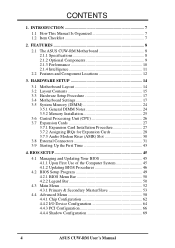
... 1.2 Item Checklist Check that your retailer. (1) ASUS Motherboard (1) 40-pin 80-conductor ribbon cable for internal UltraDMA/66 or UltraDMA/ 33 IDE drives (1) Ribbon cable for (1) 5.25" and (2) 3.5" floppy disk drives (1) Serial COM2 connector with bracket (1) Bag of spare jumper caps (1) Support CD with drivers and utilities (1) This Motherboard User's Manual LCD connector with bracket (for LCD model only) ASUS IrDA-compliant infrared module (optional) ASUS consumer infrared set (optional) ASUS PCI-L101 Wake-On-LAN 10/100 ethernet card (optional) ASUS CUW-RM User's Manual 7
... 1.2 Item Checklist Check that your retailer. (1) ASUS Motherboard (1) 40-pin 80-conductor ribbon cable for internal UltraDMA/66 or UltraDMA/ 33 IDE drives (1) Ribbon cable for (1) 5.25" and (2) 3.5" floppy disk drives (1) Serial COM2 connector with bracket (1) Bag of spare jumper caps (1) Support CD with drivers and utilities (1) This Motherboard User's Manual LCD connector with bracket (for LCD model only) ASUS IrDA-compliant infrared module (optional) ASUS consumer infrared set (optional) ASUS PCI-L101 Wake-On-LAN 10/100 ethernet card (optional) ASUS CUW-RM User's Manual 7
CUW-RM User Manual
Page 8
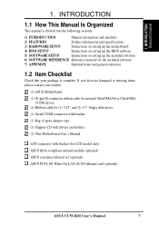
FEATURES 2.1 The ASUS CUW-RM Motherboard The CUW-RM motherboard from ASUS is enabled. Allows processor settings and easy overclocking of frequency and Vcore voltage all through BIOS setup when JumperFree™ mode is carefully designed for the demanding PC user who wants many smart features in case you want to 17MB/s. • Peripheral Wake-Up! Supports processors with EPP and ECP capabilities. • Integrated IDE! You can support a Bus Master PCI card (such as IDE controllers, USB controllers, and PCI addon cards. • Multi...
FEATURES 2.1 The ASUS CUW-RM Motherboard The CUW-RM motherboard from ASUS is enabled. Allows processor settings and easy overclocking of frequency and Vcore voltage all through BIOS setup when JumperFree™ mode is carefully designed for the demanding PC user who wants many smart features in case you want to 17MB/s. • Peripheral Wake-Up! Supports processors with EPP and ECP capabilities. • Integrated IDE! You can support a Bus Master PCI card (such as IDE controllers, USB controllers, and PCI addon cards. • Multi...
CUW-RM User Manual
Page 9
... Internet transactions. 2.1.2 Optional Components The following onboard components are optional at the time of most devices for connecting a digital flat panel (analog flat panel must be connected to the VGA-out connector) to -digital conversions, which provides more control and protection over the motherboard. ASUS CUW-RM User's Manual 9 Programmable BIOS (Flash EEPROM), offering enhanced ACPI for Windows 98 compatibility, built-in firmware-based virus protection, and autodetection of purchase: • Smart Audio! Software Audio and Hardware...
... Internet transactions. 2.1.2 Optional Components The following onboard components are optional at the time of most devices for connecting a digital flat panel (analog flat panel must be connected to the VGA-out connector) to -digital conversions, which provides more control and protection over the motherboard. ASUS CUW-RM User's Manual 9 Programmable BIOS (Flash EEPROM), offering enhanced ACPI for Windows 98 compatibility, built-in firmware-based virus protection, and autodetection of purchase: • Smart Audio! Software Audio and Hardware...

CUW-RM User Manual
Page 10
... an exciting gameplay experience. 10 ASUS CUW-RM User's Manual Onboard IDE Bus Master controller with concurrent PCI and CPU bus activities. • SDRAM Optimized Performance! ASUS smart series motherboards support the new generation memory, Synchronous Dynamic Random Access Memory (SDRAM), which increases the data transfer rate to upgrade current IDE devices or cables. • Concurrent PCI! FEATURES 2.1.3 Performance • UltraPerformance! Suspend-To-RAM (STR) provides maximum power savings as Tape Backup, CD-ROM, CD-R/RW, and LS...
... an exciting gameplay experience. 10 ASUS CUW-RM User's Manual Onboard IDE Bus Master controller with concurrent PCI and CPU bus activities. • SDRAM Optimized Performance! ASUS smart series motherboards support the new generation memory, Synchronous Dynamic Random Access Memory (SDRAM), which increases the data transfer rate to upgrade current IDE devices or cables. • Concurrent PCI! FEATURES 2.1.3 Performance • UltraPerformance! Suspend-To-RAM (STR) provides maximum power savings as Tape Backup, CD-ROM, CD-R/RW, and LS...
CUW-RM User Manual
Page 11
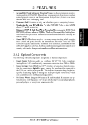
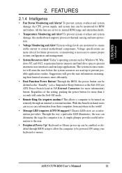
... the user information on -hand, users can be enabled or disabled through an internal or external modem. Regardless of the setting, pushing the power button for its normal RPM range and alarm thresholds. • Temperature Monitoring and Alert! With this motherboard supports processor thermal sensing and auto-protection. • Voltage Monitoring and Alert! Keyboard or Mouse power up to be powered ON using your keyboard or mouse. All the fans are monitored to...
... the user information on -hand, users can be enabled or disabled through an internal or external modem. Regardless of the setting, pushing the power button for its normal RPM range and alarm thresholds. • Temperature Monitoring and Alert! With this motherboard supports processor thermal sensing and auto-protection. • Voltage Monitoring and Alert! Keyboard or Mouse power up to be powered ON using your keyboard or mouse. All the fans are monitored to...
CUW-RM User Manual
Page 12
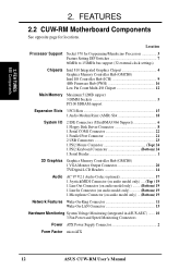
... 2.2 CUW-RM Motherboard Components See opposite page for Coppermine/Mendocino Processors 3 Feature Setting DIP Switches 7 66MHz to 150MHz bus support (32 external clock settings) Chipsets Intel 810 Integrated Graphics Chipset 4 Graphics Memory Controller Hub (GMCH0) Intel I/O Controller Hub (ICH 9 4Mb Firmware Hub (FWH 16 Low Pin Count Multi-I/O Chipset 12 Main Memory Maximum 512MB support 3 DIMM Sockets 5 PC100 SDRAM support Expansion Slots 3 PCI Slots 15 1 Audio Modem Riser (AMR) Slot 18 System I/O 2 IDE Connectors (UltraDMA33/66 Support 6 1 Floppy Disk Driver Connector...
... 2.2 CUW-RM Motherboard Components See opposite page for Coppermine/Mendocino Processors 3 Feature Setting DIP Switches 7 66MHz to 150MHz bus support (32 external clock settings) Chipsets Intel 810 Integrated Graphics Chipset 4 Graphics Memory Controller Hub (GMCH0) Intel I/O Controller Hub (ICH 9 4Mb Firmware Hub (FWH 16 Low Pin Count Multi-I/O Chipset 12 Main Memory Maximum 512MB support 3 DIMM Sockets 5 PC100 SDRAM support Expansion Slots 3 PCI Slots 15 1 Audio Modem Riser (AMR) Slot 18 System I/O 2 IDE Connectors (UltraDMA33/66 Support 6 1 Floppy Disk Driver Connector...
CUW-RM User Manual
Page 14
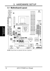
... ASUS CUW-RM User's Manual H/W SETUP Motherboard Layout 3. HARDWARE SETUP 3.1 Motherboard Layout PS/2 T: Mouse B: Keyboard VIO USB T: Port1 B: Port2 COM1 CPU_FAN DIMM Socket 1 (64/72-bit, 168-pin module) DIMM Socket 2 (64/72-bit, 168-pin module) DIMM Socket 3 (64/72-bit, 168-pin module) Secondary IDE Primary IDE FLOPPY ATX Power Connector PARALLEL PORT GAME_AUDIO Socket 370 PWR_FAN VGA Line Out COM2 LCDTV0 IR_CON Line In Mic In MIC2 VIDEO AUX Super I/O CD LCDTV1 TAD Audio Modem Riser (AMR) Intel 810 Graphics & Memory Controller Hub Audio...
... ASUS CUW-RM User's Manual H/W SETUP Motherboard Layout 3. HARDWARE SETUP 3.1 Motherboard Layout PS/2 T: Mouse B: Keyboard VIO USB T: Port1 B: Port2 COM1 CPU_FAN DIMM Socket 1 (64/72-bit, 168-pin module) DIMM Socket 2 (64/72-bit, 168-pin module) DIMM Socket 3 (64/72-bit, 168-pin module) Secondary IDE Primary IDE FLOPPY ATX Power Connector PARALLEL PORT GAME_AUDIO Socket 370 PWR_FAN VGA Line Out COM2 LCDTV0 IR_CON Line In Mic In MIC2 VIDEO AUX Super I/O CD LCDTV1 TAD Audio Modem Riser (AMR) Intel 810 Graphics & Memory Controller Hub Audio...

CUW-RM User Manual
Page 15
...LED Lead (2 pins) 14) CHA_, CPU_, PWR_FAN p.36 Chassis, CPU, Power Supply Fan Connectors (Three 3-pin) 15) IR_CON p.37 Infrared Module Connectors (10-1 pins) 16) COM2 p.37 Serial Port COM2 Header (10-1 pins) 17) SMB p.38 SMBus Connector (5-1 pins) 18) LCDTV0/LCDTV1 p.38 LCD-TV Headers (Two 14 pins) (optional) 19) TAD, AUX, VIDEO, CD p.39 Internal Audio Connectors (Four 4-pins) 20) MIC2 p.39 Internal Microphone Connector (3 pins) 21) ACHA p.40 Chassis Intrusion Lead (2-pins) 22) ATXPWR p.40 ATX Power Supply Connector (20 pins) ASUS CUW-RM User's Manual 15 3. H/W SETUP Layout...
...LED Lead (2 pins) 14) CHA_, CPU_, PWR_FAN p.36 Chassis, CPU, Power Supply Fan Connectors (Three 3-pin) 15) IR_CON p.37 Infrared Module Connectors (10-1 pins) 16) COM2 p.37 Serial Port COM2 Header (10-1 pins) 17) SMB p.38 SMBus Connector (5-1 pins) 18) LCDTV0/LCDTV1 p.38 LCD-TV Headers (Two 14 pins) (optional) 19) TAD, AUX, VIDEO, CD p.39 Internal Audio Connectors (Four 4-pins) 20) MIC2 p.39 Internal Microphone Connector (3 pins) 21) ACHA p.40 Chassis Intrusion Lead (2-pins) 22) ATXPWR p.40 ATX Power Supply Connector (20 pins) ASUS CUW-RM User's Manual 15 3. H/W SETUP Layout...
CUW-RM User Manual
Page 19
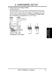
... Codec Setting 3 3 2 2 1 1 ADN# AUD_EN2 Enable Disable 3. Disable the onboard audio codec if you are using a PCI audio expansion card, Onboard AC'97 Audio Controller in this section). If using a PCI audio card on any of the expansion slots or a primary AMR on audio model only The onboard audio codec may be disabled. H/W SETUP Motherboard Settings ASUS CUW-RM User's Manual 19 3. HARDWARE SETUP 3) Onboard Audio Codec Setting (CODEC) on the AMR slot (see AMR Slot later in 4.4.2 I/O Device Configuration must also be enabled or disabled using all of these jumpers.
... Codec Setting 3 3 2 2 1 1 ADN# AUD_EN2 Enable Disable 3. Disable the onboard audio codec if you are using a PCI audio expansion card, Onboard AC'97 Audio Controller in this section). If using a PCI audio card on any of the expansion slots or a primary AMR on audio model only The onboard audio codec may be disabled. H/W SETUP Motherboard Settings ASUS CUW-RM User's Manual 19 3. HARDWARE SETUP 3) Onboard Audio Codec Setting (CODEC) on the AMR slot (see AMR Slot later in 4.4.2 I/O Device Configuration must also be enabled or disabled using all of these jumpers.
CUW-RM User Manual
Page 20
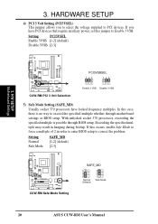
... Safe Mode to exceed the specified multiple whether through BIOS setup. With unlocked socket 370 processors, exceeding the specified multiple is no way to force a multiple of 2 in hanging during bootup. 3. If this jumper to correct the problem. Exceeding the specified multiple may result in order to enter BIOS setup to Enable 3 VSB. Setting PCI3VSEL Enable 3VSB [1-2] (default) Disable 3VSB [2-3] 3. Setting Normal Safe Mode SAFE_MD [1-2] (default) [2-3] CUW-RM ® CUW-RM Safe Mode Setting SAFE_MD 3 2 1 Normal (Default) 3 2 1 Safe Mode 20 ASUS CUW-RM User's Manual...
... Safe Mode to exceed the specified multiple whether through BIOS setup. With unlocked socket 370 processors, exceeding the specified multiple is no way to force a multiple of 2 in hanging during bootup. 3. If this jumper to correct the problem. Exceeding the specified multiple may result in order to enter BIOS setup to Enable 3 VSB. Setting PCI3VSEL Enable 3VSB [1-2] (default) Disable 3VSB [2-3] 3. Setting Normal Safe Mode SAFE_MD [1-2] (default) [2-3] CUW-RM ® CUW-RM Safe Mode Setting SAFE_MD 3 2 1 Normal (Default) 3 2 1 Safe Mode 20 ASUS CUW-RM User's Manual...
CUW-RM User Manual
Page 34
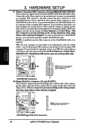
...the jumper settings. one operating system on an IDE drive and another UltraDMA/66 cable. IMPORTANT: UltraDMA/66 IDE devices must configure the second drive to the secondary IDE connector. H/W SETUP Connectors CUW-RM ® NOTE: Orient the red markings on the IDE ribbon cable to PIN 1 PIN 1 CUW-RM Floppy Disk Drive Connector 34 ASUS CUW-RM User's Manual HARDWARE SETUP 9) Primary / Secondary IDE Connectors (40-1 pin PRIMARY/SECONDARY) These connectors support the provided UltraDMA/66 IDE hard disk ribbon cable. Refer to prevent inserting in 4.6 Boot Menu. Secondary IDE Connector...
...the jumper settings. one operating system on an IDE drive and another UltraDMA/66 cable. IMPORTANT: UltraDMA/66 IDE devices must configure the second drive to the secondary IDE connector. H/W SETUP Connectors CUW-RM ® NOTE: Orient the red markings on the IDE ribbon cable to PIN 1 PIN 1 CUW-RM Floppy Disk Drive Connector 34 ASUS CUW-RM User's Manual HARDWARE SETUP 9) Primary / Secondary IDE Connectors (40-1 pin PRIMARY/SECONDARY) These connectors support the provided UltraDMA/66 IDE hard disk ribbon cable. Refer to prevent inserting in 4.6 Boot Menu. Secondary IDE Connector...
CUW-RM User Manual
Page 43
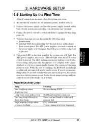
... three short beeps High frequency beeps when system is working Meaning No error during POST No DRAM installed or detected Video card not found or video card memory bad CPU overheated System running , the BIOS will alarm beeps or additional messages will light when the ATX power switch is equipped with "green" standards or if it has a power standby feature. Connect the power cord into the power supply located on your devices in the following order: a. You may then turn...
... three short beeps High frequency beeps when system is working Meaning No error during POST No DRAM installed or detected Video card not found or video card memory bad CPU overheated System running , the BIOS will alarm beeps or additional messages will light when the ATX power switch is equipped with "green" standards or if it has a power standby feature. Connect the power cord into the power supply located on your devices in the following order: a. You may then turn...
CUW-RM User Manual
Page 45
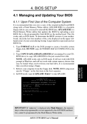
... in DOS mode. This file works only in case you boot from the floppy disk. Reboot your computer from your motherboard, check the last four numbers of the Computer System It is not supported by the Flash Memory Writer utility. ASUS CUW-RM User's Manual 45 To determine the BIOS version of the original motherboard BIOS along with certain memory drivers that you save a copy of your hard drive. If "unknown" is displayed after Flash Memory:, the memory chip is...
... in DOS mode. This file works only in case you boot from the floppy disk. Reboot your computer from your motherboard, check the last four numbers of the Computer System It is not supported by the Flash Memory Writer utility. ASUS CUW-RM User's Manual 45 To determine the BIOS version of the original motherboard BIOS along with certain memory drivers that you save a copy of your hard drive. If "unknown" is displayed after Flash Memory:, the memory chip is...
CUW-RM User Manual
Page 59
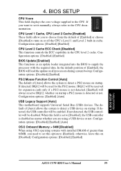
... options: [Disabled] [Enabled] 4. BIOS SETUP Advanced Menu ASUS CUW-RM User's Manual 59 If detected, IRQ12 will load the update on [Disabled]. Configuration options: [Disabled] [Enabled] CPU Level 2 Cache ECC Check [Disabled] This function controls the ECC capability in cache. The default of [Enabled], the BIOS will be disabled. Configuration options: [Disabled] [Enabled] BIOS Update [Enabled] This functions as an update loader integrated into the BIOS to [Enabled]; Configuration options: [Disabled] [Enabled] [Auto] OS/2 Onboard Memory > 64M [Disabled] When using a USB device...
... options: [Disabled] [Enabled] 4. BIOS SETUP Advanced Menu ASUS CUW-RM User's Manual 59 If detected, IRQ12 will load the update on [Disabled]. Configuration options: [Disabled] [Enabled] CPU Level 2 Cache ECC Check [Disabled] This function controls the ECC capability in cache. The default of [Enabled], the BIOS will be disabled. Configuration options: [Disabled] [Enabled] BIOS Update [Enabled] This functions as an update loader integrated into the BIOS to [Enabled]; Configuration options: [Disabled] [Enabled] [Auto] OS/2 Onboard Memory > 64M [Disabled] When using a USB device...

CUW-RM User Manual
Page 64
...Disabled] 64 ASUS CUW-RM User's Manual Configuration options: [No Swap] [Swap AB] Floppy Disk Access Control [R/W] When set the appropriate field to set the addresses for the onboard serial connectors. Configuration options: [R/W] [Read Only] Onboard Serial Port 1 [3F8H/IRQ4], Onboard Serial Port 2 [2F8H/IRQ3] These fields allow you to floppy disks by allowing reads from the floppy disk drive but not writes. If a modem/audio device is detected, the onboard modem/audio controller will be disabled. 4. BIOS SETUP I /O Device Configuration 4. BIOS SETUP 4.4.2 I /O Device Config...
...Disabled] 64 ASUS CUW-RM User's Manual Configuration options: [No Swap] [Swap AB] Floppy Disk Access Control [R/W] When set the appropriate field to set the addresses for the onboard serial connectors. Configuration options: [R/W] [Read Only] Onboard Serial Port 1 [3F8H/IRQ4], Onboard Serial Port 2 [2F8H/IRQ3] These fields allow you to floppy disks by allowing reads from the floppy disk drive but not writes. If a modem/audio device is detected, the onboard modem/audio controller will be disabled. 4. BIOS SETUP I /O Device Configuration 4. BIOS SETUP 4.4.2 I /O Device Config...
CUW-RM User Manual
Page 66
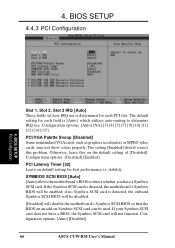
... SCSI card can be enabled; BIOS SETUP 4.4.3 PCI Configuration 4. BIOS SETUP PCI Configuration Slot 1, Slot 2, Slot 3 IRQ [Auto] These fields set how IRQ use . Configuration options: [Disabled] [Enabled] PCI Latency Timer [32] Leave on the default setting of [Disabled]. stability. SYMBIOS SCSI BIOS [Auto] [Auto] allows the motherboard's BIOS to determine IRQ use is detected, the onboard Symbios SCSI BIOS will be disabled. [Disabled] will be used. if no Symbios SCSI card is determined for best performance vs. Configuration options: [Auto] [Disabled] 66 ASUS CUW-RM User's Manual
... SCSI card can be enabled; BIOS SETUP 4.4.3 PCI Configuration 4. BIOS SETUP PCI Configuration Slot 1, Slot 2, Slot 3 IRQ [Auto] These fields set how IRQ use . Configuration options: [Disabled] [Enabled] PCI Latency Timer [32] Leave on the default setting of [Disabled]. stability. SYMBIOS SCSI BIOS [Auto] [Auto] allows the motherboard's BIOS to determine IRQ use is detected, the onboard Symbios SCSI BIOS will be disabled. [Disabled] will be used. if no Symbios SCSI card is determined for best performance vs. Configuration options: [Auto] [Disabled] 66 ASUS CUW-RM User's Manual
CUW-RM User Manual
Page 67
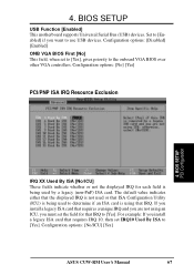
... to the onboard VGA BIOS over other VGA controllers. If you install a legacy ISA card that requires a unique IRQ and you are not using that ISA Configuration Utility (ICU) is not used by a legacy (non-PnP) ISA card. Configuration options: [No/ICU] [Yes] ASUS CUW-RM User's Manual 67 Configuration options: [No] [Yes] PCI/PNP ISA IRQ Resource Exclusion 4. The default value indicates either that the displayed IRQ is being used or that IRQ. BIOS SETUP USB Function [Enabled] This motherboard supports Universal Serial Bus (USB) devices.
... to the onboard VGA BIOS over other VGA controllers. If you install a legacy ISA card that requires a unique IRQ and you are not using that ISA Configuration Utility (ICU) is not used by a legacy (non-PnP) ISA card. Configuration options: [No/ICU] [Yes] ASUS CUW-RM User's Manual 67 Configuration options: [No] [Yes] PCI/PNP ISA IRQ Resource Exclusion 4. The default value indicates either that the displayed IRQ is being used or that IRQ. BIOS SETUP USB Function [Enabled] This motherboard supports Universal Serial Bus (USB) devices.
CUW-RM User Manual
Page 116
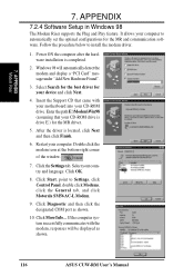
.... 116 ASUS CUW-RM User's Manual Insert the Support CD that your CD-ROM drive. Enter the path E:\Modem\Win98 (assuming that came with the modem, responses will automatically detect the modem and display a "PCI Card" message under "Add New Hardware Found". 3. After the driver is completed. 2. APPENDIX Modem Riser 7. Select Search for the best driver for the MR and communication software. Restart your device and...
.... 116 ASUS CUW-RM User's Manual Insert the Support CD that your CD-ROM drive. Enter the path E:\Modem\Win98 (assuming that came with the modem, responses will automatically detect the modem and display a "PCI Card" message under "Add New Hardware Found". 3. After the driver is completed. 2. APPENDIX Modem Riser 7. Select Search for the best driver for the MR and communication software. Restart your device and...
CUW-RM User Manual
Page 125
... Onboard VGA 63 Operating Systems 79 OS/2 Onboard Memory > 64M 59 Other Boot Device Select 75 P Parallel Port Connector 32 Parallel Port Mode 65 PC Probe Setup 91 Using 103 PC-cillin 98 Setup 94 PCI 3 Volt Setting 20 PCI Latency Timer 66 PCI/VGA Palette Snoop 66 PIO Mode 55 Plug & Play O/S 76 Power Fan Speed 74 Power Management 70 Procedure CPU Installation 26 Hardware Setup 17 Procedures Modem Riser Installation 115 Updating BIOS 46 Programs Uninstalling 96 PS/2 Keyboard Connector...
... Onboard VGA 63 Operating Systems 79 OS/2 Onboard Memory > 64M 59 Other Boot Device Select 75 P Parallel Port Connector 32 Parallel Port Mode 65 PC Probe Setup 91 Using 103 PC-cillin 98 Setup 94 PCI 3 Volt Setting 20 PCI Latency Timer 66 PCI/VGA Palette Snoop 66 PIO Mode 55 Plug & Play O/S 76 Power Fan Speed 74 Power Management 70 Procedure CPU Installation 26 Hardware Setup 17 Procedures Modem Riser Installation 115 Updating BIOS 46 Programs Uninstalling 96 PS/2 Keyboard Connector...


