Asus PCH-DL Support and Manuals
Get Help and Manuals for this Asus item
Popular Asus PCH-DL Manual Pages
User Manual - Page 13
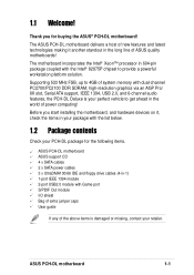
... graphics via an AGP Pro/ 8X slot, Serial ATA support, IEEE 1394, USB 2.0, and 6-channel audio features, the PCH-DL Deluxe is damaged or missing, contact your PCH-DL package for buying the ASUS® PCH-DL motherboard!
Supporting 533 MHz FSB, up to 4GB of system memory with the Intel® 82875P chipset to get ahead in the long line of power computing!
User Manual - Page 15
... Instead of boot errors, if any . The SoundMAX 4 XL software features the AudioESP™ (Audio Enumeration and Sensing Process) that allows intelligent detection of peripherals and devices compliant to 400Mbps transfer rates through the Communication Streaming Architecture (CSA).
The IEEE 1394 allows up to IEEE 1394a standards. ASUS PCH-DL motherboard
1-3 Gigabit LAN solution
The Intel...
User Manual - Page 18
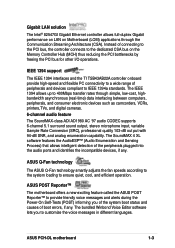
Chapter summary
2.1 Before you proceed 2-1 2.2 Motherboard installation 2-2 2.3 Central Processing Unit (CPU 2-5 2.4 System memory 2-12 2.5 Expansion slots 2-15 2.6 Jumpers 2-18 2.7 Connectors 2-21
ASUS PCH-DL motherboard
User Manual - Page 19
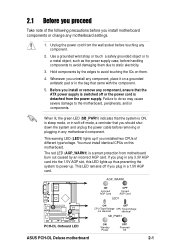
... warning LED (LED1) lights up . AGP_WARN1
ON
Incorrect AGP Card
OFF
Correct AGP Card
LED1
PCH-DL
PCH-DL Onboard LED
ON
OFF
CPU Type/Voltage CPU Type/Voltage
not identical
identical
SB_PWR1
ON
Standby Power
OFF
Powered Off
ASUS PCH-DL Deluxe motherboard
2-1 Hold components by an incorrect AGP card.
Use a grounded wrist strap or touch a safely...
User Manual - Page 25
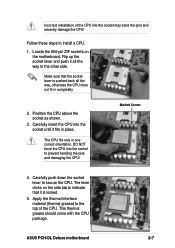
... secure the CPU. Marked Corner
4.
Position the CPU above the socket as shown.
3. Follow these steps to indicate that the socket lever is locked.
5. ASUS PCH-DL Deluxe motherboard
2-7 Locate the 604-pin ZIF sockets on the side tab to install a CPU.
1.
The lever clicks on the motherboard.
Apply the thermal interface material (thermal grease) to the other side. Incorrect...
User Manual - Page 27
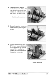
... heatsink on top of the CPU, having its holes with the four holes on the motherboard and the standoffs on the retention mechanism. Heatsink angled side
ASUS PCH-DL Deluxe motherboard
2-9
Secure the retention mechanism with cut corners) facing the memory sockets. Make sure that the heatsink base fits completely on the thermal plate. Heatsink retention mechanism...
User Manual - Page 31
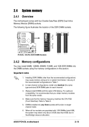
..., and 1GB DDR DIMMs into any of the DDR DIMM sockets. Refer to Southbridge resource allocation. ASUS PCH-DL motherboard
2-13 Use any three sockets will function in singlechannel mode.
6. Make sure that you obtain memory modules from the same vendor.
4. DIMMs installed into the DIMM sockets using the memory configurations in Table 1.
2. For optimum compatibility, it is recommended that...
User Manual - Page 33
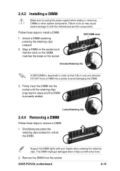
... damaging the DIMM.
3. DDR DIMM notch
Unlocked Retaining Clip
A DDR DIMM is properly seated. DO NOT force a DIMM into the socket until the retaining clips snap back in only one direction. ASUS PCH-DL motherboard
2-15 Unlock a DIMM socket by pressing the retaining clips outward.
2.
Locked Retaining Clip
2.4.4 Removing a DIMM
Follow these steps to remove a DIMM...
User Manual - Page 35
...
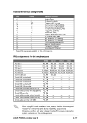
IRQ_H#
Onbd. IDE controller
IRQ_C#
Onbd. SATA controller (6300ESB ICH) IRQ_C#
Onbd. 1394 controller (TSB43AB22A) IRQ_E#
Onbd.
Otherwise, conflicts will arise between the two PCI groups, making the system unstable and the card inoperable. ASUS PCH-DL motherboard
2-17 USB controller #1
IRQ_A#
Onbd. USB controller #4
IRQ_A#
Onbd. audio controller (AD1980)
IRQ_B#
IRQ_G# IRQ_H...
User Manual - Page 37
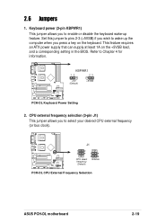
... frequency
(Default)
3
4
5
6
100MHz
PCH-DL
PCH-DL CPU External Frequency Selection
ASUS PCH-DL motherboard
2-19 Set this jumper to pins 2-3 (+5VSB) if you wish to wake up feature. KBPWR1
12
23
+5V (Default)
+5VSB
PCH-DL
PCH-DL Keyboard Power Setting
2. Keyboard power (3-pin KBPWR1) This jumper allows you to enable or disable the keyboard wake-up the computer when you to Chapter...
User Manual - Page 39
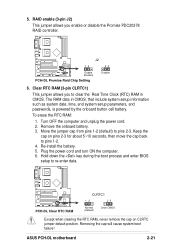
... process and enter BIOS setup to pins 2-3.
Plug the power cord and turn ON the computer. 6. The RAM data in CMOS. ASUS PCH-DL motherboard
2-21 Remove the onboard battery. 3. Keep the
cap on CLRTC jumper default position.
Removing the cap will cause system boot failure! J2
12
23
Enable (Default)
PCH-DL
PCH-DL Promise Raid Chip Setting
Disable
6. Clear RTC RAM (3-pin CLRTC1...
User Manual - Page 41
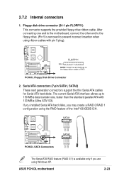
...NOTE: Orient the red markings on the floppy ribbon cable to PIN 1. ASUS PCH-DL motherboard
2-23 2.7.2 Internal connectors
1.
SATA1
GND RSATA_TXP1 RSATA_TXN1
GND RSATA_RXN1 RSATA_RXP1
GND
PCH-DL
PCH-DL SATA Connectors
GND RSATA_TXP2 RSATA_TXN2
GND RSATA_RXN2 RSATA_RXP2
GND
SATA2
The Serial ATA RAID feature (RAID 0/1) is removed to 150 MB/s data transfer rate, faster than the standard...
User Manual - Page 43
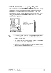
.../100/66/33 connector (40-1 pin PRI_RAID1) This connector supports either RAID 0 or RAID 1 configuration through the onboard Promise® PDC20378 controller.
ASUS PCH-DL motherboard
2-25 PIN 1
PRI_RAID1
NOTE: Orient the red markings (usually zigzag) on the Serial ATA RAID connectors to create a RAID set up the UltraATA133 hard disks with the Serial ATA hard disks on the IDE...
User Manual - Page 47
...
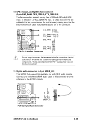
CPU_FAN1 Rotation
CPU_FAN2
+12V GND
SYS_FAN1
GND +12V Rotation
Rotation +12V GND
SYS_FAN2 SYS_FAN3
PCH-DL
PCH-DL 12-Volt Fan Connectors
Do not forget to connect the fan cables to the S/PDIF module.
+5V SPDIFOUT GND
SPDIF_01
PCH-DL
PCH-DL Digital Audio Connector
ASUS PCH-DL motherboard
2-29 Connect the fan cables to the fan connectors on the fan connectors!
11...
User Manual - Page 49
...
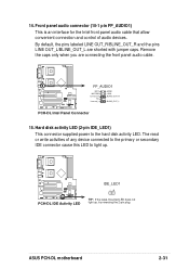
BLINE_OUT_L
PCH-DL
PCH-DL Intel Panel Connector
15.
PCH-DL
PCH-DL IDE Activity LED
IDE_LED1 -+
TIP: If the case-mounted LED does not light up .
Remove the caps only when you are shorted with jumper caps. ASUS PCH-DL motherboard
2-31 By default, the pins labeled LINE OUT_R/BLINE_OUT_R and the pins LINE OUT_L/BLINE_OUT_L are connecting the front panel audio...
Asus PCH-DL Reviews
We have not received any reviews for Asus yet.