User Manual
Page 1
Motherboard PCH-DL User Guide
Motherboard PCH-DL User Guide
User Manual
Page 3
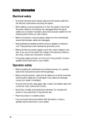
Features Contents Notices ...v Safety information vi About this guide vii PCH-DL specifications summary ix Chapter 1: Product introduction 1.1 Welcome 1-1 1.2 Package contents 1-1 1.3 Special features 1-2 Chapter 2: Hardware information 2.1 Before you proceed 2-1 2.2 Motherboard installation 2-2 2.2.1 Placement direction 2-2 2.2.2 Screw holes 2-2 2.2.3 Motherboard layout 2-3 2.2.4 Layout Contents 2-4 2.3 Central Processing Unit (CPU 2-5 2.3.1 Overview 2-5 2.3.2 Installing the CPU 2-5 2.3.3 Installing the CPU heatsink and fan 2-7 2.4 System memory...
Features Contents Notices ...v Safety information vi About this guide vii PCH-DL specifications summary ix Chapter 1: Product introduction 1.1 Welcome 1-1 1.2 Package contents 1-1 1.3 Special features 1-2 Chapter 2: Hardware information 2.1 Before you proceed 2-1 2.2 Motherboard installation 2-2 2.2.1 Placement direction 2-2 2.2.2 Screw holes 2-2 2.2.3 Motherboard layout 2-3 2.2.4 Layout Contents 2-4 2.3 Central Processing Unit (CPU 2-5 2.3.1 Overview 2-5 2.3.2 Installing the CPU 2-5 2.3.3 Installing the CPU heatsink and fan 2-7 2.4 System memory...
User Manual
Page 6
Operation safety • Before installing the motherboard and adding devices on a stable surface. • If you encounter technical problems with the package. • Before using the product, make sure all power cables ... are unplugged before the signal cables are unplugged. • Seek professional assistance before you add a device. • Before connecting or removing signal cables from the motherboard, ensure that your power supply is broken, do not try to the correct voltage in any damage, contact your retailer. If possible, disconnect all power...
Operation safety • Before installing the motherboard and adding devices on a stable surface. • If you encounter technical problems with the package. • Before using the product, make sure all power cables ... are unplugged before the signal cables are unplugged. • Seek professional assistance before you add a device. • Before connecting or removing signal cables from the motherboard, ensure that your power supply is broken, do not try to the correct voltage in any damage, contact your retailer. If possible, disconnect all power...
User Manual
Page 7
...when installing system components. It includes description of the switches, jumpers, and connectors on the motherboard. • Chapter 3: Powering up This chapter describes the power up sequence and gives information...motherboard and the new technology it supports. • Chapter 2: Hardware installation This chapter lists the hardware setup procedures that you need when installing and configuring the motherboard. About this guide is organized This manual contains the following parts: • Chapter 1: Product introduction This chapter describes the features of the PCH-DL motherboard...
...when installing system components. It includes description of the switches, jumpers, and connectors on the motherboard. • Chapter 3: Powering up This chapter describes the power up sequence and gives information...motherboard and the new technology it supports. • Chapter 2: Hardware installation This chapter lists the hardware setup procedures that you need when installing and configuring the motherboard. About this guide is organized This manual contains the following parts: • Chapter 1: Product introduction This chapter describes the features of the PCH-DL motherboard...
User Manual
Page 11
It includes brief explanations of the special attributes of the motherboard. Product introduction Chapter 1 This chapter describes the features of the motherboard and the new technology it supports.
It includes brief explanations of the special attributes of the motherboard. Product introduction Chapter 1 This chapter describes the features of the motherboard and the new technology it supports.
User Manual
Page 12
Chapter summary 1.1 Welcome 1-1 1.2 Package contents 1-1 1.3 Special features 1-2 ASUS PCH-DL motherboard
Chapter summary 1.1 Welcome 1-1 1.2 Package contents 1-1 1.3 Special features 1-2 ASUS PCH-DL motherboard
User Manual
Page 13
...chipset to get ahead in the world of power computing! 1.1 Welcome! The motherboard incorporates the Intel® Xeon™ processor in your retailer. The ASUS PCH-DL motherboard delivers a host of new features and latest technologies making it , check the ... platform solution. Before you for the following items. ASUS PCH-DL motherboard ASUS support CD 4 x SATA cables 2 x SATA power cables 3 x UltraDMA100/66 IDE and floppy drive cables (4-in the long line of the above items is your PCH-DL package for buying the ASUS® PCH-DL motherboard! ASUS PCH-DL motherboard 1-1
...chipset to get ahead in the world of power computing! 1.1 Welcome! The motherboard incorporates the Intel® Xeon™ processor in your retailer. The ASUS PCH-DL motherboard delivers a host of new features and latest technologies making it , check the ... platform solution. Before you for the following items. ASUS PCH-DL motherboard ASUS support CD 4 x SATA cables 2 x SATA power cables 3 x UltraDMA100/66 IDE and floppy drive cables (4-in the long line of the above items is your PCH-DL package for buying the ASUS® PCH-DL motherboard! ASUS PCH-DL motherboard 1-1
User Manual
Page 14
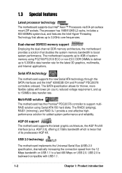
...interfaces and the Intel® 6300ESB ICH and Promise® PDC20378 controllers onboard. 1.3 Special features Latest processor technology The motherboard supports dual Intel® Xeon™ Processors via 604-pin surface mount ZIF sockets. The RAID0 (striping), RAID1 (...and RAID 0+1 provide a cost-effective highperformance solution for the latest 3D graphics, multimedia, and Internet applications. USB 2.0 technology The motherboard implements the Universal Serial Bus (USB) 2.0 specification, dramatically increasing the connection speed from the 12 Mbps bandwidth on USB 1.1 ...
...interfaces and the Intel® 6300ESB ICH and Promise® PDC20378 controllers onboard. 1.3 Special features Latest processor technology The motherboard supports dual Intel® Xeon™ Processors via 604-pin surface mount ZIF sockets. The RAID0 (striping), RAID1 (...and RAID 0+1 provide a cost-effective highperformance solution for the latest 3D graphics, multimedia, and Internet applications. USB 2.0 technology The motherboard implements the Universal Serial Bus (USB) 2.0 specification, dramatically increasing the connection speed from the 12 Mbps bandwidth on USB 1.1 ...
User Manual
Page 15
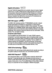
... to a wide range of boot errors, if any . ASUS Q-Fan technology The ASUS Q-Fan technology smartly adjusts the fan speeds according to the system loading to the dedicated CSA bus on Motherboard (LOM) applications through simple, low-cost, highbandwidth asynchronous (real...alerts during the Power-On Self-Tests (POST) informing you to 400Mbps transfer rates through the Communication Streaming Architecture (CSA). ASUS PCH-DL motherboard 1-3 The SoundMAX 4 XL software features the AudioESP™ (Audio Enumeration and Sensing Process) that allows intelligent detection of connecting...
... to a wide range of boot errors, if any . ASUS Q-Fan technology The ASUS Q-Fan technology smartly adjusts the fan speeds according to the system loading to the dedicated CSA bus on Motherboard (LOM) applications through simple, low-cost, highbandwidth asynchronous (real...alerts during the Power-On Self-Tests (POST) informing you to 400Mbps transfer rates through the Communication Streaming Architecture (CSA). ASUS PCH-DL motherboard 1-3 The SoundMAX 4 XL software features the AudioESP™ (Audio Enumeration and Sensing Process) that allows intelligent detection of connecting...
User Manual
Page 16
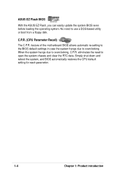
... BIOS With the ASUS EZ Flash, you can easily update the system BIOS even before loading the operating system. Simply shut down and reboot the system, and BIOS automatically ... CPU default setting for each parameter. 1-4 Chapter 1: Product introduction eliminates the need to open the system chassis and clear the RTC data. feature of the motherboard BIOS allows automatic re-setting to the BIOS default settings in case the system hangs due to overclocking, C.P.R. No need to use a DOS-based utility...
... BIOS With the ASUS EZ Flash, you can easily update the system BIOS even before loading the operating system. Simply shut down and reboot the system, and BIOS automatically ... CPU default setting for each parameter. 1-4 Chapter 1: Product introduction eliminates the need to open the system chassis and clear the RTC data. feature of the motherboard BIOS allows automatic re-setting to the BIOS default settings in case the system hangs due to overclocking, C.P.R. No need to use a DOS-based utility...
User Manual
Page 17
Chapter 2 This chapter describes the hardware setup procedures that you have to perform when installing system components. Hardware information It includes details on the switches, jumpers, and connectors on the motherboard.
Chapter 2 This chapter describes the hardware setup procedures that you have to perform when installing system components. Hardware information It includes details on the switches, jumpers, and connectors on the motherboard.
User Manual
Page 18
Chapter summary 2.1 Before you proceed 2-1 2.2 Motherboard installation 2-2 2.3 Central Processing Unit (CPU 2-5 2.4 System memory 2-12 2.5 Expansion slots 2-15 2.6 Jumpers 2-18 2.7 Connectors 2-21 ASUS PCH-DL motherboard
Chapter summary 2.1 Before you proceed 2-1 2.2 Motherboard installation 2-2 2.3 Central Processing Unit (CPU 2-5 2.4 System memory 2-12 2.5 Expansion slots 2-15 2.6 Jumpers 2-18 2.7 Connectors 2-21 ASUS PCH-DL motherboard
User Manual
Page 19
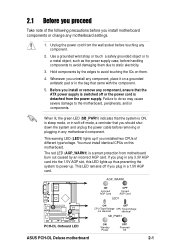
...to static electricity. 3. AGP_WARN1 ON Incorrect AGP Card OFF Correct AGP Card LED1 PCH-DL PCH-DL Onboard LED ON OFF CPU Type/Voltage CPU Type/Voltage not identical identical SB_PWR1 ON Standby Power OFF Powered Off ASUS PCH-DL Deluxe motherboard 2-1 Failure to do so may cause severe damage to power up if you ... . 4. Hold components by an incorrect AGP card. The red LED (AGP_WARN1) is detached from the power supply. Unplug the power cord from motherboard burn out caused by the edges to avoid touching the ICs on this LED lights up thus preventing the system to the...
...to static electricity. 3. AGP_WARN1 ON Incorrect AGP Card OFF Correct AGP Card LED1 PCH-DL PCH-DL Onboard LED ON OFF CPU Type/Voltage CPU Type/Voltage not identical identical SB_PWR1 ON Standby Power OFF Powered Off ASUS PCH-DL Deluxe motherboard 2-1 Failure to do so may cause severe damage to power up if you ... . 4. Hold components by an incorrect AGP card. The red LED (AGP_WARN1) is detached from the power supply. Unplug the power cord from motherboard burn out caused by the edges to avoid touching the ICs on this LED lights up thus preventing the system to the...
User Manual
Page 20
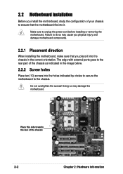
...not overtighten the screws! Make sure to do so may damage the motherboard. Doing so may cause you physical injury and damage motherboard components. 2.2.1 Placement direction When installing the motherboard, make sure that the motherboard fits into the chassis in the image below. 2.2.2 Screw holes Place... the power cord before installing or removing the motherboard. The edge with external ports goes to the rear part of the chassis as indicated in the correct orientation. 2.2 Motherboard installation Before you install the motherboard, study the configuration of your chassis to the...
...not overtighten the screws! Make sure to do so may damage the motherboard. Doing so may cause you physical injury and damage motherboard components. 2.2.1 Placement direction When installing the motherboard, make sure that the motherboard fits into the chassis in the image below. 2.2.2 Screw holes Place... the power cord before installing or removing the motherboard. The edge with external ports goes to the rear part of the chassis as indicated in the correct orientation. 2.2 Motherboard installation Before you install the motherboard, study the configuration of your chassis to the...
User Manual
Page 21
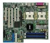
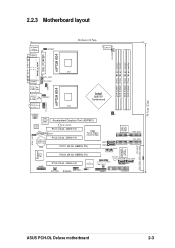
2.2.3 Motherboard layout PS/2KBMS T: Mouse B: Keyboard COM1 KBPWR1 26.8cm (10.5in) CON12V CHA FAN1 DDR DIMM1 (72 bit, 184-pin module) DDR DIMM2 (72 bit, ... 4Mbit Flash BIOS SEC_IDE1 PRI_IDE1 PROMISE PDC20378 RAID Controller PRI_RAID1 Super I/O GAME1 PCIX2 (64-bit, 66MHz 3V) PCI3 (32-bit, 33MHz 5V) TI TSB43AB22A SYS_FAN1 PCH-DL IEEE1394_1 J3 SB_PWR1 SATA_RAID1 SATA_RAID2 CLRTC1 CHASSIS1 IDE_LED1 SMB1 PANEL1 FLOPPY1 30.5cm (12in) ASUS PCH-DL Deluxe motherboard 2-3
2.2.3 Motherboard layout PS/2KBMS T: Mouse B: Keyboard COM1 KBPWR1 26.8cm (10.5in) CON12V CHA FAN1 DDR DIMM1 (72 bit, 184-pin module) DDR DIMM2 (72 bit, ... 4Mbit Flash BIOS SEC_IDE1 PRI_IDE1 PROMISE PDC20378 RAID Controller PRI_RAID1 Super I/O GAME1 PCIX2 (64-bit, 66MHz 3V) PCI3 (32-bit, 33MHz 5V) TI TSB43AB22A SYS_FAN1 PCH-DL IEEE1394_1 J3 SB_PWR1 SATA_RAID1 SATA_RAID2 CLRTC1 CHASSIS1 IDE_LED1 SMB1 PANEL1 FLOPPY1 30.5cm (12in) ASUS PCH-DL Deluxe motherboard 2-3
User Manual
Page 23
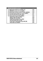
...) 2-32 - Internal connectors (continued) 11. Power switch / Soft-off switch (2-pin PWR_SW) 2-32 - Hard disk activity (2-pin HD_LED) 2-32 - Reset switch (2-pin RESET) 2-32 ASUS PCH-DL Deluxe motherboard 2-5 Digital audio connector (4-1 pin SPDIF_O1) 2-29 12. System warning speaker (4-pin SPKR) 2-32 - Message LED (2-pin MLED) 2-32 - System panel connector (20-pin PANEL) 2-32...
...) 2-32 - Internal connectors (continued) 11. Power switch / Soft-off switch (2-pin PWR_SW) 2-32 - Hard disk activity (2-pin HD_LED) 2-32 - Reset switch (2-pin RESET) 2-32 ASUS PCH-DL Deluxe motherboard 2-5 Digital audio connector (4-1 pin SPDIF_O1) 2-29 12. System warning speaker (4-pin SPKR) 2-32 - Message LED (2-pin MLED) 2-32 - System panel connector (20-pin PANEL) 2-32...
User Manual
Page 24
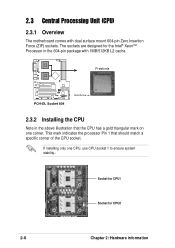
... a specific corner of the CPU socket. Prestonia PCH-DL PCH-DL Socket 604 Gold Arrow 2.3.2 Installing the CPU Note in the 604-pin package with dual surface mount 604-pin Zero Insertion Force (ZIF) sockets. If installing only one corner. 2.3 Central Processing Unit (CPU) 2.3.1 Overview The motherboard comes with 1MB/512KB L2 cache. The sockets...
... a specific corner of the CPU socket. Prestonia PCH-DL PCH-DL Socket 604 Gold Arrow 2.3.2 Installing the CPU Note in the 604-pin package with dual surface mount 604-pin Zero Insertion Force (ZIF) sockets. If installing only one corner. 2.3 Central Processing Unit (CPU) 2.3.1 Overview The motherboard comes with 1MB/512KB L2 cache. The sockets...
User Manual
Page 25
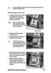
...prevent bending the pins and damaging the CPU! The CPU fits only in completely. 2. Carefully push down the socket lever to install a CPU. 1. ASUS PCH-DL Deluxe motherboard 2-7 Locate the 604-pin ZIF sockets on the side tab to indicate that the socket lever is locked. 5. Flip up the socket lever and push...the CPU into the socket until it all the way, otherwise the CPU does not fit in one correct orientation. The lever clicks on the motherboard. This thermal grease should come with the CPU package. Apply the thermal interface material (thermal grease) to the top of the CPU into ...
...prevent bending the pins and damaging the CPU! The CPU fits only in completely. 2. Carefully push down the socket lever to install a CPU. 1. ASUS PCH-DL Deluxe motherboard 2-7 Locate the 604-pin ZIF sockets on the side tab to indicate that the socket lever is locked. 5. Flip up the socket lever and push...the CPU into the socket until it all the way, otherwise the CPU does not fit in one correct orientation. The lever clicks on the motherboard. This thermal grease should come with the CPU package. Apply the thermal interface material (thermal grease) to the top of the CPU into ...
User Manual
Page 26
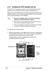
... manual, and other items that came with the four holes around the CPU socket. Refer to the top of the motherboard holes and standoffs. When you motherboard into the chassis. 2. Make sure that you have applied the thermal grease to the installation manual that are necessary for... Standoff CPU thermal plate 2-8 Chapter 2: Hardware information Perform the installation steps 1 to ensure optimum thermal condition and performance. With the motherboard on a flat stable surface (such as a table), place the thermal plate underneath a CPU socket, matching the standoffs on the plate...
... manual, and other items that came with the four holes around the CPU socket. Refer to the top of the motherboard holes and standoffs. When you motherboard into the chassis. 2. Make sure that you have applied the thermal grease to the installation manual that are necessary for... Standoff CPU thermal plate 2-8 Chapter 2: Hardware information Perform the installation steps 1 to ensure optimum thermal condition and performance. With the motherboard on a flat stable surface (such as a table), place the thermal plate underneath a CPU socket, matching the standoffs on the plate...
User Manual
Page 27
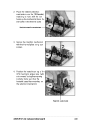
Place the heatsink retention mechanism over the CPU socket, matching its angled side (with cut corners) facing the memory sockets. Heatsink retention mechanism 3. Heatsink angled side ASUS PCH-DL Deluxe motherboard 2-9 2. Make sure that the heatsink base fits completely on the thermal plate. Secure the retention mechanism with the four holes on the motherboard and the standoffs on the retention mechanism. Position the heatsink on top of the CPU, having its holes with the thermal plate using four screws. 4.
Place the heatsink retention mechanism over the CPU socket, matching its angled side (with cut corners) facing the memory sockets. Heatsink retention mechanism 3. Heatsink angled side ASUS PCH-DL Deluxe motherboard 2-9 2. Make sure that the heatsink base fits completely on the thermal plate. Secure the retention mechanism with the four holes on the motherboard and the standoffs on the retention mechanism. Position the heatsink on top of the CPU, having its holes with the thermal plate using four screws. 4.


