CUW-RM User Manual
Page 1
® CUW-RM Intel® 810 microATX Motherboard USER'S MANUAL
® CUW-RM Intel® 810 microATX Motherboard USER'S MANUAL
CUW-RM User Manual
Page 2
... purchaser for each product design represented by the digit before and after the period of the manual revision number. Copyright © 1999 ASUSTeK COMPUTER INC. Product Name: Manual Revision: Release Date: ASUS CUW-RM 1.01 E487 December 1999 2 ASUS CUW-RM User's Manual Product warranty or service will not be extended if: (1) the product is repaired, modified or altered...
... purchaser for each product design represented by the digit before and after the period of the manual revision number. Copyright © 1999 ASUSTeK COMPUTER INC. Product Name: Manual Revision: Release Date: ASUS CUW-RM 1.01 E487 December 1999 2 ASUS CUW-RM User's Manual Product warranty or service will not be extended if: (1) the product is repaired, modified or altered...
CUW-RM User Manual
Page 3
... 150 Li-Te Road, Peitou, Taipei, Taiwan 112 Telephone: +886-2-2894-3447 Fax: +886-2-2894-3449 Email: info@asus.com.tw Technical Support MB/Others (Tel): +886-2-2890-7121 (English) Notebook (Tel): +886-2-2890-7122 (English) ...Desktop/Server (Tel):+886-2-2890-7123 (English) Fax: +886-2-2895-9254 Email: tsd@asus.com.tw WWW: www.asus.com.tw FTP: ftp.asus.com.tw/pub/ASUS ASUS COMPUTER INTERNATIONAL (America) Marketing Address: 6737 Mowry Avenue, Mowry Business Center, Building 2 Newark,...) WWW: www.asuscom.de FTP: ftp.asuscom.de/pub/ASUSCOM ASUS CUW-RM User's Manual 3
... 150 Li-Te Road, Peitou, Taipei, Taiwan 112 Telephone: +886-2-2894-3447 Fax: +886-2-2894-3449 Email: info@asus.com.tw Technical Support MB/Others (Tel): +886-2-2890-7121 (English) Notebook (Tel): +886-2-2890-7122 (English) ...Desktop/Server (Tel):+886-2-2890-7123 (English) Fax: +886-2-2895-9254 Email: tsd@asus.com.tw WWW: www.asus.com.tw FTP: ftp.asus.com.tw/pub/ASUS ASUS COMPUTER INTERNATIONAL (America) Marketing Address: 6737 Mowry Avenue, Mowry Business Center, Building 2 Newark,...) WWW: www.asuscom.de FTP: ftp.asuscom.de/pub/ASUSCOM ASUS CUW-RM User's Manual 3
CUW-RM User Manual
Page 4
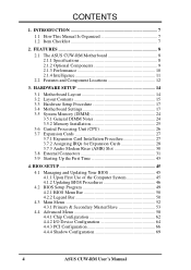
FEATURES 8 2.1 The ASUS CUW-RM Motherboard 8 2.1.1 Specifications 8 2.1.2 Optional Components 9 2.1.3 Performance 10 2.1.4 Intelligence 11 2.2 Features and Component Locations 12 3. HARDWARE SETUP 14 3.1 Motherboard Layout 14 3.2 Layout Contents 15 3.3 ...4.3 Main Menu 52 4.3.1 Primary & Secondary Master/Slave 53 4.4 Advanced Menu 58 4.4.1 Chip Configuration 62 4.4.2 I/O Device Configuration 64 4.4.3 PCI Configuration 66 4.4.4 Shadow Configuration 69 4 ASUS CUW-RM User's Manual INTRODUCTION 7 1.1 How This Manual Is Organized 7 1.2 Item Checklist 7 2. CONTENTS 1.
FEATURES 8 2.1 The ASUS CUW-RM Motherboard 8 2.1.1 Specifications 8 2.1.2 Optional Components 9 2.1.3 Performance 10 2.1.4 Intelligence 11 2.2 Features and Component Locations 12 3. HARDWARE SETUP 14 3.1 Motherboard Layout 14 3.2 Layout Contents 15 3.3 ...4.3 Main Menu 52 4.3.1 Primary & Secondary Master/Slave 53 4.4 Advanced Menu 58 4.4.1 Chip Configuration 62 4.4.2 I/O Device Configuration 64 4.4.3 PCI Configuration 66 4.4.4 Shadow Configuration 69 4 ASUS CUW-RM User's Manual INTRODUCTION 7 1.1 How This Manual Is Organized 7 1.2 Item Checklist 7 2. CONTENTS 1.
CUW-RM User Manual
Page 5
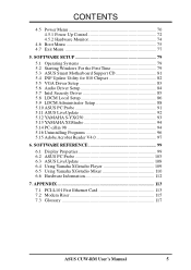
... Using Yamaha XGstudio Mixer 110 6.6 Hardware Information 112 7. SOFTWARE SETUP 79 5.1 Operating Systems 79 5.2 Starting Windows For the First Time 79 5.3 ASUS Smart Motherboard Support CD 81 5.4 INF Update Utility for 810 Chipset 82 5.5 VGA Driver Setup 83 5.6 Audio Driver Setup 84 5.7 Intel Security Driver... Adobe Acrobat Reader V4.0 97 6. APPENDIX 113 7.1 PCI-L101 Fast Ethernet Card 113 7.2 Modem Riser 115 7.3 Glossary 117 ASUS CUW-RM User's Manual 5 CONTENTS 4.5 Power Menu 70 4.5.1 Power Up Control 72 4.5.2 Hardware Monitor 74 4.6 Boot Menu 75 4.7 Exit Menu 77 5.
... Using Yamaha XGstudio Mixer 110 6.6 Hardware Information 112 7. SOFTWARE SETUP 79 5.1 Operating Systems 79 5.2 Starting Windows For the First Time 79 5.3 ASUS Smart Motherboard Support CD 81 5.4 INF Update Utility for 810 Chipset 82 5.5 VGA Driver Setup 83 5.6 Audio Driver Setup 84 5.7 Intel Security Driver... Adobe Acrobat Reader V4.0 97 6. APPENDIX 113 7.1 PCI-L101 Fast Ethernet Card 113 7.2 Modem Riser 115 7.3 Glossary 117 ASUS CUW-RM User's Manual 5 CONTENTS 4.5 Power Menu 70 4.5.1 Power Up Control 72 4.5.2 Hardware Monitor 74 4.6 Boot Menu 75 4.7 Exit Menu 77 5.
CUW-RM User Manual
Page 6
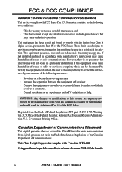
... one or more of the FCC Rules. Cet appareil numérique de la classe B est conforme à la norme NMB-003 du Canada. 6 ASUS CUW-RM User's Manual Any changes or modifications to this equipment does cause harmful interference to radio or television reception, which the receiver is encouraged to try to correct...
... one or more of the FCC Rules. Cet appareil numérique de la classe B est conforme à la norme NMB-003 du Canada. 6 ASUS CUW-RM User's Manual Any changes or modifications to this equipment does cause harmful interference to radio or television reception, which the receiver is encouraged to try to correct...
CUW-RM User Manual
Page 7
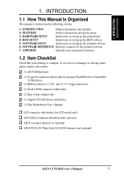
... SOFTWARE REFERENCE Reference material for the included software 7) APPENDIX Optional items and general reference 1.2 Item Checklist Check that your retailer. (1) ASUS Motherboard (1) 40-pin 80-conductor ribbon cable for internal UltraDMA/66 or UltraDMA/ 33 IDE drives (1) Ribbon cable for (1) 5.25... utilities (1) This Motherboard User's Manual LCD connector with bracket (for LCD model only) ASUS IrDA-compliant infrared module (optional) ASUS consumer infrared set (optional) ASUS PCI-L101 Wake-On-LAN 10/100 ethernet card (optional) ASUS CUW-RM User's Manual 7 If you discover damaged or...
... SOFTWARE REFERENCE Reference material for the included software 7) APPENDIX Optional items and general reference 1.2 Item Checklist Check that your retailer. (1) ASUS Motherboard (1) 40-pin 80-conductor ribbon cable for internal UltraDMA/66 or UltraDMA/ 33 IDE drives (1) Ribbon cable for (1) 5.25... utilities (1) This Motherboard User's Manual LCD connector with bracket (for LCD model only) ASUS IrDA-compliant infrared module (optional) ASUS consumer infrared set (optional) ASUS PCI-L101 Wake-On-LAN 10/100 ethernet card (optional) ASUS CUW-RM User's Manual 7 If you discover damaged or...
CUW-RM User Manual
Page 8
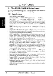
... Mode 4 up to 17MB/s. • Peripheral Wake-Up! Audio Modem Riser slot supports a very affordable audio and/or modem riser card. 8 ASUS CUW-RM User's Manual FEATURES 2.1 The ASUS CUW-RM Motherboard The CUW-RM motherboard from ASUS is enabled. Controller supports 3D hyper pipelined architecture, parallel data processing and compression, precise pixel interpolation, full 2D hardware acceleration, and motion...
... Mode 4 up to 17MB/s. • Peripheral Wake-Up! Audio Modem Riser slot supports a very affordable audio and/or modem riser card. 8 ASUS CUW-RM User's Manual FEATURES 2.1 The ASUS CUW-RM Motherboard The CUW-RM motherboard from ASUS is enabled. Controller supports 3D hyper pipelined architecture, parallel data processing and compression, precise pixel interpolation, full 2D hardware acceleration, and motion...
CUW-RM User Manual
Page 9
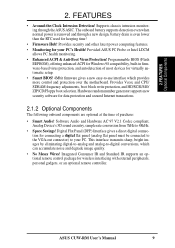
... Windows 98 compatibility, built-in firmware-based virus protection, and autodetection of purchase: • Smart Audio! ASUS CUW-RM User's Manual 9 Supports chassis intrusion monitoring through a new design, battery drain is removed and through the ASUS ASIC. Provided ASUS PC Probe or Intel LDCM allows PC health monitoring. • Enhanced ACPI & Anti-Boot Virus Protection! This...
... Windows 98 compatibility, built-in firmware-based virus protection, and autodetection of purchase: • Smart Audio! ASUS CUW-RM User's Manual 9 Supports chassis intrusion monitoring through a new design, battery drain is removed and through the ASUS ASIC. Provided ASUS PC Probe or Intel LDCM allows PC health monitoring. • Enhanced ACPI & Anti-Boot Virus Protection! This...

CUW-RM User Manual
Page 10
...signal to 800MB/s max using UltraDMA/66 technology. The integrated motion compensation allows for an exciting gameplay experience. 10 ASUS CUW-RM User's Manual AC'97 DAC/ADC built into the audio codec reduces noise to improve audio quality and performance for Windows 95/...Play compatibility and power management for future operating systems (OS) supporting OS Direct Power Management (OSPM) functionality. FEATURES Performance 2. ASUS smart series motherboards support the new generation memory, Synchronous Dynamic Random Access Memory (SDRAM), which increases the data transfer rate ...
...signal to 800MB/s max using UltraDMA/66 technology. The integrated motion compensation allows for an exciting gameplay experience. 10 ASUS CUW-RM User's Manual AC'97 DAC/ADC built into the audio codec reduces noise to improve audio quality and performance for Windows 95/...Play compatibility and power management for future operating systems (OS) supporting OS Direct Power Management (OSPM) functionality. FEATURES Performance 2. ASUS smart series motherboards support the new generation memory, Synchronous Dynamic Random Access Memory (SDRAM), which increases the data transfer rate ...
CUW-RM User Manual
Page 11
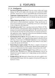
... Function Power Button! Suggestions will enter the Soft-Off mode. • Remote Ring On (requires modem)! Suspend or Sleep) button or as the "Standby" (a.k.a. ASUS CUW-RM User's Manual 11 2. FEATURES 2.1.4 Intelligence • Fan Status Monitoring and Alarm! Chassis LEDs now act as Windows 98, Windows NT, and OS/2, require much more information) button...
... Function Power Button! Suggestions will enter the Soft-Off mode. • Remote Ring On (requires modem)! Suspend or Sleep) button or as the "Standby" (a.k.a. ASUS CUW-RM User's Manual 11 2. FEATURES 2.1.4 Intelligence • Fan Status Monitoring and Alarm! Chassis LEDs now act as Windows 98, Windows NT, and OS/2, require much more information) button...
CUW-RM User Manual
Page 12
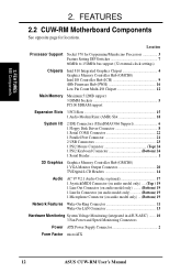
2. FEATURES MB Components 2. Location Processor Support Socket 370 for locations. FEATURES 2.2 CUW-RM Motherboard Components See opposite page for Coppermine/Mendocino Processors 3 Feature Setting DIP Switches 7 66MHz to 150MHz bus support (32 external clock settings)...model only) ... (Bottom) 19 Network Features Wake-On-Ring Connector 11 Wake-On-LAN Connector 13 Hardware Monitoring System Voltage Monitoring (integrated in ASUS ASIC) ....... 10 3 Fan Power and Speed Monitoring Connectors Power ATX Power Supply Connector 2 Form Factor microATX 12 ASUS CUW-RM User's Manual
2. FEATURES MB Components 2. Location Processor Support Socket 370 for locations. FEATURES 2.2 CUW-RM Motherboard Components See opposite page for Coppermine/Mendocino Processors 3 Feature Setting DIP Switches 7 66MHz to 150MHz bus support (32 external clock settings)...model only) ... (Bottom) 19 Network Features Wake-On-Ring Connector 11 Wake-On-LAN Connector 13 Hardware Monitoring System Voltage Monitoring (integrated in ASUS ASIC) ....... 10 3 Fan Power and Speed Monitoring Connectors Power ATX Power Supply Connector 2 Form Factor microATX 12 ASUS CUW-RM User's Manual
CUW-RM User Manual
Page 14
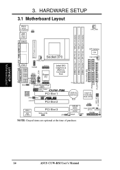
...Mic In MIC2 VIDEO AUX Super I/O CD LCDTV1 TAD Audio Modem Riser (AMR) Intel 810 Graphics & Memory Controller Hub Audio Codec Setting CUW-RM Audio Codec PCI Slot 1 PCI3VSBSEL SPDO SPDI ® AUDIOEN PCI Slot 2 4Mbit Firmware Hub (FWH) PCI Slot 3 WOL_CON JEN ... 00 11 2 3 3 2 CR2032 3V Lithium Cell CMOS Power Intel I/O Controller Hub (ICH) SMB ASUS ASIC Clear CMOS with Hardware Monitor (R191) ACHA WOR JTPWR PANEL NOTE: Grayed items are optional at the time of purchase. SAFE_MD NO_REBOOT IDELED 14 ASUS CUW-RM User's Manual H/W SETUP Motherboard Layout 3. 3.
...Mic In MIC2 VIDEO AUX Super I/O CD LCDTV1 TAD Audio Modem Riser (AMR) Intel 810 Graphics & Memory Controller Hub Audio Codec Setting CUW-RM Audio Codec PCI Slot 1 PCI3VSBSEL SPDO SPDI ® AUDIOEN PCI Slot 2 4Mbit Firmware Hub (FWH) PCI Slot 3 WOL_CON JEN ... 00 11 2 3 3 2 CR2032 3V Lithium Cell CMOS Power Intel I/O Controller Hub (ICH) SMB ASUS ASIC Clear CMOS with Hardware Monitor (R191) ACHA WOR JTPWR PANEL NOTE: Grayed items are optional at the time of purchase. SAFE_MD NO_REBOOT IDELED 14 ASUS CUW-RM User's Manual H/W SETUP Motherboard Layout 3. 3.
CUW-RM User Manual
Page 15
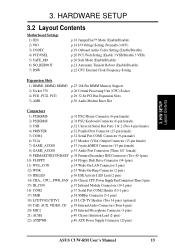
... (Four 4-pins) 20) MIC2 p.39 Internal Microphone Connector (3 pins) 21) ACHA p.40 Chassis Intrusion Lead (2-pins) 22) ATXPWR p.40 ATX Power Supply Connector (20 pins) ASUS CUW-RM User's Manual 15 H/W SETUP Layout Contents 3. 3.
... (Four 4-pins) 20) MIC2 p.39 Internal Microphone Connector (3 pins) 21) ACHA p.40 Chassis Intrusion Lead (2-pins) 22) ATXPWR p.40 ATX Power Supply Connector (20 pins) ASUS CUW-RM User's Manual 15 H/W SETUP Layout Contents 3. 3.
CUW-RM User Manual
Page 16
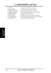
3. HARDWARE SETUP 23) JTPWR 24) PLED (PANEL) 25) KEYLOCK (PANEL) 26) SPEAKER (PANEL) 27) RESET (PANEL) 28) PWR (PANEL) 29) EXTSMI (PANEL) 30) LED (PANEL) p.41 Thermal Sensor Connector (2 pins) p.42 System Power LED Lead (3-1 pins) p.42 Keyboard Lock Switch Lead (2 pins) p.42 System Warning Speaker Connector (4 pins) p.42 Reset Switch Lead (2 pins) p.42 ATX Power / Soft-Off Switch Lead (2 pins) p.42 System Management Interrupt Switch Lead (2 pins) p.42 System Message LED (2 pins) 3. H/W SETUP Layout Contents 16 ASUS CUW-RM User's Manual
3. HARDWARE SETUP 23) JTPWR 24) PLED (PANEL) 25) KEYLOCK (PANEL) 26) SPEAKER (PANEL) 27) RESET (PANEL) 28) PWR (PANEL) 29) EXTSMI (PANEL) 30) LED (PANEL) p.41 Thermal Sensor Connector (2 pins) p.42 System Power LED Lead (3-1 pins) p.42 Keyboard Lock Switch Lead (2 pins) p.42 System Warning Speaker Connector (4 pins) p.42 Reset Switch Lead (2 pins) p.42 ATX Power / Soft-Off Switch Lead (2 pins) p.42 System Management Interrupt Switch Lead (2 pins) p.42 System Message LED (2 pins) 3. H/W SETUP Layout Contents 16 ASUS CUW-RM User's Manual
CUW-RM User Manual
Page 17
.... 3. Computer motherboards and expansion cards contain very delicate Integrated Circuit (IC) chips. Use a grounded wrist strap before handling computer components. WARNING! H/W SETUP Motherboard Settings ASUS CUW-RM User's Manual 17 Place components on a grounded antistatic pad or on the inside. 2. 3. Hold components by the edges and try not to a metal object, such as the...
.... 3. Computer motherboards and expansion cards contain very delicate Integrated Circuit (IC) chips. Use a grounded wrist strap before handling computer components. WARNING! H/W SETUP Motherboard Settings ASUS CUW-RM User's Manual 17 Place components on a grounded antistatic pad or on the inside. 2. 3. Hold components by the edges and try not to a metal object, such as the...
CUW-RM User Manual
Page 18
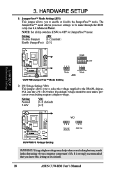
...may result in the shortening of your computer component's life. Setting Normal 3.66V VIO [1-2] (default) [2-3] CUW-RM ® VIO 123 Normal (Default) 123 3.66 Volt CUW-RM I /O buffer. It is strongly recommended that you to select the voltage supplied to be used unless ...Menu). H/W SETUP Motherboard Settings CUW-RM ® 123 DSW ON 12345 123 OFF Jumper Mode JumperFree Mode JEN CUW-RM JumperFree™ Mode Setting 2) I/O Voltage Setting (VIO) This jumper allows you leave this setting on its default. 18 ASUS CUW-RM User's Manual The JumperFree™ mode allows ...
...may result in the shortening of your computer component's life. Setting Normal 3.66V VIO [1-2] (default) [2-3] CUW-RM ® VIO 123 Normal (Default) 123 3.66 Volt CUW-RM I /O buffer. It is strongly recommended that you to select the voltage supplied to be used unless ...Menu). H/W SETUP Motherboard Settings CUW-RM ® 123 DSW ON 12345 123 OFF Jumper Mode JumperFree Mode JEN CUW-RM JumperFree™ Mode Setting 2) I/O Voltage Setting (VIO) This jumper allows you leave this setting on its default. 18 ASUS CUW-RM User's Manual The JumperFree™ mode allows ...
CUW-RM User Manual
Page 19
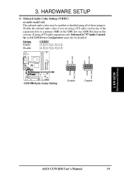
H/W SETUP Motherboard Settings ASUS CUW-RM User's Manual 19 3. Disable the onboard audio codec if you are using all of the expansion slots or a primary AMR on audio model only The onboard audio... also be enabled or disabled using a PCI audio card on any of these jumpers. Setting Enable CODEC [1-2] [1-2] [1-2] [1-2] Disable [2-3] [2-3] [2-3] [2-3] SPK AUD_EN1 SPK AUD_EN1 ADN# AUD_EN2 CUW-RM ® CUW-RM Audio Codec Setting 3 3 2 2 1 1 ADN# AUD_EN2 Enable Disable 3. HARDWARE SETUP 3) Onboard Audio Codec Setting (CODEC) on the AMR slot (see AMR Slot later in this...
H/W SETUP Motherboard Settings ASUS CUW-RM User's Manual 19 3. Disable the onboard audio codec if you are using all of the expansion slots or a primary AMR on audio model only The onboard audio... also be enabled or disabled using a PCI audio card on any of these jumpers. Setting Enable CODEC [1-2] [1-2] [1-2] [1-2] Disable [2-3] [2-3] [2-3] [2-3] SPK AUD_EN1 SPK AUD_EN1 ADN# AUD_EN2 CUW-RM ® CUW-RM Audio Codec Setting 3 3 2 2 1 1 ADN# AUD_EN2 Enable Disable 3. HARDWARE SETUP 3) Onboard Audio Codec Setting (CODEC) on the AMR slot (see AMR Slot later in this...
CUW-RM User Manual
Page 20
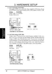
... is no way to PCI devices. Setting Normal Safe Mode SAFE_MD [1-2] (default) [2-3] CUW-RM ® CUW-RM Safe Mode Setting SAFE_MD 3 2 1 Normal (Default) 3 2 1 Safe Mode 20 ASUS CUW-RM User's Manual If this case, there is possible through motherboard settings or BIOS setup. H/W SETUP Motherboard Settings CUW-RM ® CUW-RM PCI 3 Volt Selection PCI3VSBSEL 123 123 Enable 3 VSB Disable 3 VSB 5) Safe...
... is no way to PCI devices. Setting Normal Safe Mode SAFE_MD [1-2] (default) [2-3] CUW-RM ® CUW-RM Safe Mode Setting SAFE_MD 3 2 1 Normal (Default) 3 2 1 Safe Mode 20 ASUS CUW-RM User's Manual If this case, there is possible through motherboard settings or BIOS setup. H/W SETUP Motherboard Settings CUW-RM ® CUW-RM PCI 3 Volt Selection PCI3VSBSEL 123 123 Enable 3 VSB Disable 3 VSB 5) Safe...

CUW-RM User Manual
Page 21
H/W SETUP Motherboard Settings ASUS CUW-RM User's Manual 21 If rebooting is set this jumper to No Reboot to disable auto-reboot. Setting Normal No Reboot NO_REBOOT [1-2] (default) [2-3] CUW-RM ® CUW-RM Reboot Setting NO_REBOOT 3 2 1 Normal (Default) 3 2 1 No Reboot 3. HARDWARE SETUP 6) Automatic Timeout Reboot Setting (NO_REBOOT) The motherboard is repeating ineffectively, set so that when the BIOS detects a hang (timeout) during bootup, the motherboard will automatically reboot. 3.
H/W SETUP Motherboard Settings ASUS CUW-RM User's Manual 21 If rebooting is set this jumper to No Reboot to disable auto-reboot. Setting Normal No Reboot NO_REBOOT [1-2] (default) [2-3] CUW-RM ® CUW-RM Reboot Setting NO_REBOOT 3 2 1 Normal (Default) 3 2 1 No Reboot 3. HARDWARE SETUP 6) Automatic Timeout Reboot Setting (NO_REBOOT) The motherboard is repeating ineffectively, set so that when the BIOS detects a hang (timeout) during bootup, the motherboard will automatically reboot. 3.


