Motherboard DIY Troubleshooting Guide
Page 5
... LAN_USB34 VIA KM400A Top:Line In Center:Line Out Below:Mic In Accelerated Graphics Port (AGP1) VIA VT6103 SPDIF AD1888 FP_AUDIO PCI1 A7V400-MX SE PCI2 CR2032 3V Lithium Cell CMOS Power VIA VT8237 PCI3 CLRTC USBPWR56 USBPWR78 SB_PWR AUX CD USB56 USB78 2Mbit ISA BIOS SATA2 SATA1...+5V Ground Ground Speaker PANEL PLED SPEAKER HD_LED+ HD_LEDExtSMI# Ground PWRBIN Ground Reset Ground RESET HDLED PWRBTN SMI * Requires an ATX power supply. ASUS A7V400-MX SE-Motherboard 5 Deutsch 1. Prozessoren mit einer Taktfrequenz von kleiner 1 GHz dürfen nicht verwendet werden.
... LAN_USB34 VIA KM400A Top:Line In Center:Line Out Below:Mic In Accelerated Graphics Port (AGP1) VIA VT6103 SPDIF AD1888 FP_AUDIO PCI1 A7V400-MX SE PCI2 CR2032 3V Lithium Cell CMOS Power VIA VT8237 PCI3 CLRTC USBPWR56 USBPWR78 SB_PWR AUX CD USB56 USB78 2Mbit ISA BIOS SATA2 SATA1...+5V Ground Ground Speaker PANEL PLED SPEAKER HD_LED+ HD_LEDExtSMI# Ground PWRBIN Ground Reset Ground RESET HDLED PWRBTN SMI * Requires an ATX power supply. ASUS A7V400-MX SE-Motherboard 5 Deutsch 1. Prozessoren mit einer Taktfrequenz von kleiner 1 GHz dürfen nicht verwendet werden.
A7V400-MX SE user's manual for English version
Page 1
Motherboard A7V400-MX SE
Motherboard A7V400-MX SE
A7V400-MX SE user's manual for English version
Page 3
Contents Notices v Safety information vi About this guide vii A7V400-MX SE specifications summary viii Chapter 1: Product introduction 1.1 1.2 1.3 1.4 1.5 1.6 1.7 1.8 1.9 1.10 Welcome 1-2 Package contents 1-2 Special features 1-2 1.3.1 Product highlights 1-2 1.3.2 Innovative ASUS features 1-4 Before you proceed 1-5 Motherboard overview 1-6 1.5.1 Motherboard layout 1-6 1.5.2 Placement direction 1-7 1.5.3 Screw holes 1-7 Central Processing Unit (CPU 1-8 1.6.1 Overview 1-8 1.6.2 Installing the CPU 1-8 System memory 1-9 1.7.1 Overview 1-9 1.7.2 Memory configurations 1-9 ...
Contents Notices v Safety information vi About this guide vii A7V400-MX SE specifications summary viii Chapter 1: Product introduction 1.1 1.2 1.3 1.4 1.5 1.6 1.7 1.8 1.9 1.10 Welcome 1-2 Package contents 1-2 Special features 1-2 1.3.1 Product highlights 1-2 1.3.2 Innovative ASUS features 1-4 Before you proceed 1-5 Motherboard overview 1-6 1.5.1 Motherboard layout 1-6 1.5.2 Placement direction 1-7 1.5.3 Screw holes 1-7 Central Processing Unit (CPU 1-8 1.6.1 Overview 1-8 1.6.2 Installing the CPU 1-8 System memory 1-9 1.7.1 Overview 1-9 1.7.2 Memory configurations 1-9 ...
A7V400-MX SE user's manual for English version
Page 6
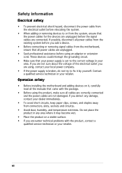
Operation safety • Before installing the motherboard and adding devices on a stable surface. • If you encounter technical problems with the package. • Before using the product, make sure all power cables ... electrical shock hazard, disconnect the power cable from the electrical outlet before relocating the system. • When adding or removing devices to or from the motherboard, ensure that all cables are correctly connected and the power cables are not damaged.
Operation safety • Before installing the motherboard and adding devices on a stable surface. • If you encounter technical problems with the package. • Before using the product, make sure all power cables ... electrical shock hazard, disconnect the power cable from the electrical outlet before relocating the system. • When adding or removing devices to or from the motherboard, ensure that all cables are correctly connected and the power cables are not damaged.

A7V400-MX SE user's manual for English version
Page 11
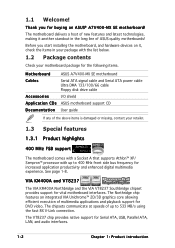
This chapter describes the motherboard features and the new technologies it supports. 1Product introduction
This chapter describes the motherboard features and the new technologies it supports. 1Product introduction
A7V400-MX SE user's manual for English version
Page 12
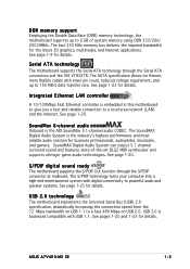
...; XP/ Sempron™ processor with the list below. 1.2 Package contents Check your motherboard package for the following items. Motherboard ASUS A7V400-MX SE motherboard Cables Serial ATA signal cable and Serial ATA power cable Ultra DMA 133/100/66 cable Floppy disk drive cable Accessories I/O shield A p p l i c a t i o n C D s ASUS motherboard support CD D o c u m e n t a t i o n User guide If any of up to 533 MB...
...; XP/ Sempron™ processor with the list below. 1.2 Package contents Check your motherboard package for the following items. Motherboard ASUS A7V400-MX SE motherboard Cables Serial ATA signal cable and Serial ATA power cable Ultra DMA 133/100/66 cable Floppy disk drive cable Accessories I/O shield A p p l i c a t i o n C D s ASUS motherboard support CD D o c u m e n t a t i o n User guide If any of up to 533 MB...
A7V400-MX SE user's manual for English version
Page 13
...VIA VT8237R. The S/PDIF technology turns your computer into a high-end entertainment system with USB 1.1. USB 2.0 technology The motherboard implements the Universal Serial Bus (USB) 2.0 specification, dramatically increasing the connection speed from the 12 Mbps bandwidth on USB...Serial ATA technology The motherboard supports the Serial ATA technology through the S/PDIF connector at midboard. Integrated Ethernet LAN controller A 10/100Mbps Fast Ethernet controller is backward compatible with digital connectivity to a fast 480 Mbps on USB 2.0. ASUS A7V400-MX SE 1-3 See page 1-9...
...VIA VT8237R. The S/PDIF technology turns your computer into a high-end entertainment system with USB 1.1. USB 2.0 technology The motherboard implements the Universal Serial Bus (USB) 2.0 specification, dramatically increasing the connection speed from the 12 Mbps bandwidth on USB...Serial ATA technology The motherboard supports the Serial ATA technology through the S/PDIF connector at midboard. Integrated Ethernet LAN controller A 10/100Mbps Fast Ethernet controller is backward compatible with digital connectivity to a fast 480 Mbps on USB 2.0. ASUS A7V400-MX SE 1-3 See page 1-9...

A7V400-MX SE user's manual for English version
Page 15
...object, such as the power supply case, before removing or plugging in soft-off or the p o w e r c o r d i s d e t a c h e d f r o m t h e p o w e r s u p p l y . Onboard LED The motherboard comes with the component. • Before you install or remove any component, ensure that the ATX power supply is ON, in sleep mode, or in... pad or in the bag that came with a standby power LED that the system is switched off mode. A7V400-MX SE A7V400-MX SE Onboard LED SB_PWR ON Standby Power OFF Powered Off ASUS A7V400-MX SE 1-5 1.4 Before you proceed Take note of the onboard LED.
...object, such as the power supply case, before removing or plugging in soft-off or the p o w e r c o r d i s d e t a c h e d f r o m t h e p o w e r s u p p l y . Onboard LED The motherboard comes with the component. • Before you install or remove any component, ensure that the ATX power supply is ON, in sleep mode, or in... pad or in the bag that came with a standby power LED that the system is switched off mode. A7V400-MX SE A7V400-MX SE Onboard LED SB_PWR ON Standby Power OFF Powered Off ASUS A7V400-MX SE 1-5 1.4 Before you proceed Take note of the onboard LED.
A7V400-MX SE user's manual for English version
Page 16
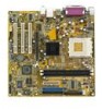
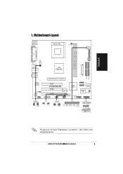
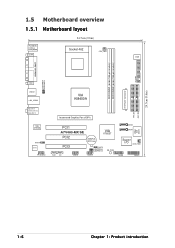
1.5 Motherboard overview 1.5.1 Motherboard layout 24.5cm (9.6in) PS/2KBMS T: Mouse B: Keyboard COM1 Socket 462 CPU_FAN DSW FLOPPY DDR DIMM1 (64 bit,184-pin module) DDR DIMM2 (64 bit,... USBPWR12 VGA1 USB12 LAN_USB34 VIA KM400A Top:Line In Center:Line Out Below:Mic In VIA VT6103 SPDIF AD1888 FP_AUDIO Accelerated Graphics Port (AGP1) PCI1 A7V400-MX SE PCI2 CR2032 3V Lithium Cell CMOS Power VIA VT8237 PCI3 CLRTC USBPWR56 USBPWR78 SB_PWR AUX CD USB56 USB78 2Mbit ISA BIOS SATA2 SATA1 Super I/O CHA_FAN1...
1.5 Motherboard overview 1.5.1 Motherboard layout 24.5cm (9.6in) PS/2KBMS T: Mouse B: Keyboard COM1 Socket 462 CPU_FAN DSW FLOPPY DDR DIMM1 (64 bit,184-pin module) DDR DIMM2 (64 bit,... USBPWR12 VGA1 USB12 LAN_USB34 VIA KM400A Top:Line In Center:Line Out Below:Mic In VIA VT6103 SPDIF AD1888 FP_AUDIO Accelerated Graphics Port (AGP1) PCI1 A7V400-MX SE PCI2 CR2032 3V Lithium Cell CMOS Power VIA VT8237 PCI3 CLRTC USBPWR56 USBPWR78 SB_PWR AUX CD USB56 USB78 2Mbit ISA BIOS SATA2 SATA1 Super I/O CHA_FAN1...
A7V400-MX SE user's manual for English version
Page 17
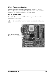
Do not overtighten the screws! Doing so can damage the motherboard. Place this side towards the rear of the chassis as indicated in the image below. 1.5.3 Screw holes Place eight (8) screws into the chassis in the correct orientation. The edge with external ports goes to the chassis. 1.5.2 Placement direction When installing the motherboard, make sure that you place it into the holes indicated by circles to secure the motherboard to the rear part of the chassis ASUS A7V400-MX SE 1-7
Do not overtighten the screws! Doing so can damage the motherboard. Place this side towards the rear of the chassis as indicated in the image below. 1.5.3 Screw holes Place eight (8) screws into the chassis in the correct orientation. The edge with external ports goes to the chassis. 1.5.2 Placement direction When installing the motherboard, make sure that you place it into the holes indicated by circles to secure the motherboard to the rear part of the chassis ASUS A7V400-MX SE 1-7
A7V400-MX SE user's manual for English version
Page 18
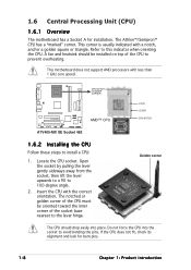
The Athlon™/Sempron™ CPU has a "marked" corner. This motherboard does not support AMD processors with a notch, and/or a golden square or triangle. Do not force the CPU into place. A fan and heatsink ...socket, then lift the lever upwards to a 90 to install a CPU: 1. 1.6 Central Processing Unit (CPU) 1.6.1 Overview The motherboard has a Socket A for bent pins. 1-8 Chapter 1: Product introduction A7V400-MX SE CPU NOTCH TO INNER CORNER AMD™ CPU LOCK LEVER CPU NOTCH A7V400-MX SE Socket 462 1.6.2 Installing the CPU Follow these steps to 100-degree angle. 2.
The Athlon™/Sempron™ CPU has a "marked" corner. This motherboard does not support AMD processors with a notch, and/or a golden square or triangle. Do not force the CPU into place. A fan and heatsink ...socket, then lift the lever upwards to a 90 to install a CPU: 1. 1.6 Central Processing Unit (CPU) 1.6.1 Overview The motherboard has a Socket A for bent pins. 1-8 Chapter 1: Product introduction A7V400-MX SE CPU NOTCH TO INNER CORNER AMD™ CPU LOCK LEVER CPU NOTCH A7V400-MX SE Socket 462 1.6.2 Installing the CPU Follow these steps to 100-degree angle. 2.
A7V400-MX SE user's manual for English version
Page 19
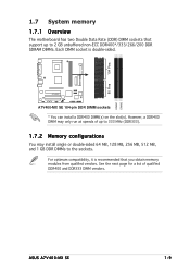
... DDR DIMM sockets * You can install a DDR400 DIMM(s) on the slot(s). DIMM1 DIMM2 ASUS A7V400-MX SE 1-9 However, a DDR400 DIMM may install single or double-sided 64 MB, 128 MB, 256 MB, 512 MB, and 1 GB DDR DIMMs to 2 GB unbuffered non-... is recommended that you obtain memory modules from qualified vendors. For optimum compatibility, it is double-sided. 104 Pins 80 Pins 1.7 System memory 1.7.1 Overview The motherboard has two Double Data Rate (DDR) DIMM sockets that support up to 333 MHz (DDR333). 1.7.2 Memory configurations You may only run at speeds of qualified...
... DDR DIMM sockets * You can install a DDR400 DIMM(s) on the slot(s). DIMM1 DIMM2 ASUS A7V400-MX SE 1-9 However, a DDR400 DIMM may install single or double-sided 64 MB, 128 MB, 256 MB, 512 MB, and 1 GB DDR DIMMs to 2 GB unbuffered non-... is recommended that you obtain memory modules from qualified vendors. For optimum compatibility, it is double-sided. 104 Pins 80 Pins 1.7 System memory 1.7.1 Overview The motherboard has two Double Data Rate (DDR) DIMM sockets that support up to 333 MHz (DDR333). 1.7.2 Memory configurations You may only run at speeds of qualified...
A7V400-MX SE user's manual for English version
Page 23
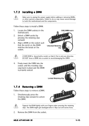
... both the motherboard and the components. Unlock a DIMM socket by pressing the retaining clips outward. 3. Firmly insert the DIMM into a socket to remove a DIMM. 1. The DIMM might get damaged when it fits in only one direction. Follow these steps to avoid damaging the DIMM. 4. ASUS A7V400-MX SE 1-13 A...Support the DIMM lightly with extra force. 2. DO NOT force a DIMM into the socket until the retaining clips snap back in the motherboard. Failure to do so may cause severe damage to unplug the power supply before adding or removing DIMMs or other system components. Remove ...
... both the motherboard and the components. Unlock a DIMM socket by pressing the retaining clips outward. 3. Firmly insert the DIMM into a socket to remove a DIMM. 1. The DIMM might get damaged when it fits in only one direction. Follow these steps to avoid damaging the DIMM. 4. ASUS A7V400-MX SE 1-13 A...Support the DIMM lightly with extra force. 2. DO NOT force a DIMM into the socket until the retaining clips snap back in the motherboard. Failure to do so may cause severe damage to unplug the power supply before adding or removing DIMMs or other system components. Remove ...
A7V400-MX SE user's manual for English version
Page 24
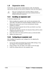
.... 1-14 Chapter 1: Product introduction Assign an IRQ to do so may need to use . 4. Failure to the card. Remove the system unit cover (if your motherboard is completely seated on BIOS setup. 2. Remove the bracket opposite the slot that you intend to install expansion cards. Make sure to the tables on..., configure the it and make the necessary hardware settings for later use . 1.8 Expansion slots In the future, you may cause you physical injury and damage motherboard components. 1.8.1 Installing an expansion card To install an expansion card: 1.
.... 1-14 Chapter 1: Product introduction Assign an IRQ to do so may need to use . 4. Failure to the card. Remove the system unit cover (if your motherboard is completely seated on BIOS setup. 2. Remove the bracket opposite the slot that you intend to install expansion cards. Make sure to the tables on..., configure the it and make the necessary hardware settings for later use . 1.8 Expansion slots In the future, you may cause you physical injury and damage motherboard components. 1.8.1 Installing an expansion card To install an expansion card: 1.
A7V400-MX SE user's manual for English version
Page 25
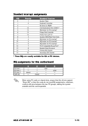
When using PCI cards on shared slots, ensure that the drivers support "Share IRQ" or that the cards do not need IRQ assignments; shared - ASUS A7V400-MX SE 1-15 D - otherwise, conflicts will arise between the two PCI groups, making the system unstable and the card inoperable. Standard interrupt assignments IRQ Priority 0.../2 Compatible Mouse Port* Numeric Data Processor Primary IDE Channel Secondary IDE Channel * These IRQs are usually available for this motherboard PCI slot 1 PCI slot 2 PCI slot 3 AGP slot A - - B - - - used - - - IRQ assignments for ISA or PCI devices...
When using PCI cards on shared slots, ensure that the drivers support "Share IRQ" or that the cards do not need IRQ assignments; shared - ASUS A7V400-MX SE 1-15 D - otherwise, conflicts will arise between the two PCI groups, making the system unstable and the card inoperable. Standard interrupt assignments IRQ Priority 0.../2 Compatible Mouse Port* Numeric Data Processor Primary IDE Channel Secondary IDE Channel * These IRQs are usually available for this motherboard PCI slot 1 PCI slot 2 PCI slot 3 AGP slot A - - B - - - used - - - IRQ assignments for ISA or PCI devices...
A7V400-MX SE user's manual for English version
Page 26
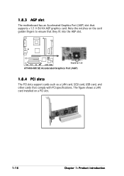
A7V400-MX SE Keyed for 1.5v A7V400-MX SE Accelerated Graphics Port (AGP) 1.8.4 PCI slots The PCI slots support cards such as a LAN card, SCSI card, USB card, and other cards that supports +1.5 V 8X/4X AGP graphics card. The figure shows a LAN card installed on the card golden fingers to ensure that they fit into the AGP slot. 1.8.3 AGP slot The motherboard has an Accelerated Graphics Port (AGP) slot that comply with PCI specifications. Note the notches on a PCI slot. 1-16 Chapter 1: Product introduction
A7V400-MX SE Keyed for 1.5v A7V400-MX SE Accelerated Graphics Port (AGP) 1.8.4 PCI slots The PCI slots support cards such as a LAN card, SCSI card, USB card, and other cards that supports +1.5 V 8X/4X AGP graphics card. The figure shows a LAN card installed on the card golden fingers to ensure that they fit into the AGP slot. 1.8.3 AGP slot The motherboard has an Accelerated Graphics Port (AGP) slot that comply with PCI specifications. Note the notches on a PCI slot. 1-16 Chapter 1: Product introduction
A7V400-MX SE user's manual for English version
Page 27
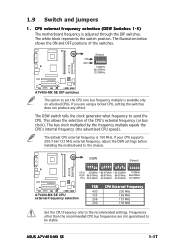
... installing the motherboard to the recommended settings. DSW O1 2 3 4 5 O1 2 3 4 5 N N O1 2 3 4 5 N (Default) O1 2 3 4 5 N CPU 200MHz 166.67MHz 133.33MHz 100MHz AGP 66.67MHz 66.67MHz 66.67MHz 66.67MHz PCI 33.33MHz 33.33MHz 33.33MHz 33.33MHz A7V400-MX SE A7V400-MX SE CPU external ... white block represents the switch position. ASUS A7V400-MX SE 1-17 The bus clock multiplied by the frequency multiple equals the CPU's internal frequency (the advertised CPU speed). A7V400-MX SE ON OFF (Default) O1 2 3 4 5 N 100MHz 66.67MHz 33.33MHz A7V400-MX SE DIP switches The option to send the...
... installing the motherboard to the recommended settings. DSW O1 2 3 4 5 O1 2 3 4 5 N N O1 2 3 4 5 N (Default) O1 2 3 4 5 N CPU 200MHz 166.67MHz 133.33MHz 100MHz AGP 66.67MHz 66.67MHz 66.67MHz 66.67MHz PCI 33.33MHz 33.33MHz 33.33MHz 33.33MHz A7V400-MX SE A7V400-MX SE CPU external ... white block represents the switch position. ASUS A7V400-MX SE 1-17 The bus clock multiplied by the frequency multiple equals the CPU's internal frequency (the advertised CPU speed). A7V400-MX SE ON OFF (Default) O1 2 3 4 5 N 100MHz 66.67MHz 33.33MHz A7V400-MX SE DIP switches The option to send the...

A7V400-MX SE user's manual for English version
Page 31
... Refer to the hard disk documentation for the jumper settings. • Pin 20 on the Ultra DMA cable connector. A7V400-MX SE PIN 1 A7V400-MX SE Floppy disk drive connector 2 . This prevents incorrect insertion when you must configure the second drive as a slave device by... 1 . IDE connectors (40-1 pin PRI_IDE, SEC_IDE) This connector is removed to PIN 1. A7V400-MX SE A7V400-MX SE IDE connectors ASUS A7V400-MX SE PRI_IDE SEC_IDE NOTE: Orient the red markings (usually zigzag) on the motherboard, a black connector for an Ultra DMA 133/100/66 IDE slave device (optical drive/hard disk...
... Refer to the hard disk documentation for the jumper settings. • Pin 20 on the Ultra DMA cable connector. A7V400-MX SE PIN 1 A7V400-MX SE Floppy disk drive connector 2 . This prevents incorrect insertion when you must configure the second drive as a slave device by... 1 . IDE connectors (40-1 pin PRI_IDE, SEC_IDE) This connector is removed to PIN 1. A7V400-MX SE A7V400-MX SE IDE connectors ASUS A7V400-MX SE PRI_IDE SEC_IDE NOTE: Orient the red markings (usually zigzag) on the motherboard, a black connector for an Ultra DMA 133/100/66 IDE slave device (optical drive/hard disk...
A7V400-MX SE user's manual for English version
Page 32
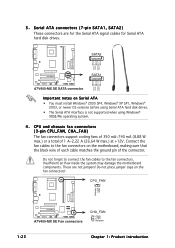
Do not place jumper caps on the motherboard, making sure that the black wire of each cable matches the ground pin of 1 A~2.22 A (26.64 W max.) at +12V. CPU_FAN Rotation +12V GND A7V400-MX SE A7V400-MX SE Fan connectors CHA_FAN GND +12V Rotation 1-22 Chapter ...connectors! 3 . Insufficient air flow inside the system may damage the motherboard components. SATA2 GND RSATA_TXP2 RSATA_TXN2 GND RSATA_RXP2 RSATA_RXN2 GND A7V400-MX SE SATA1 GND RSATA_TXP1 RSATA_TXN1 GND RSATA_RXP1 RSATA_RXN1 GND A7V400-MX SE SATA connector Important notes on Serial ATA • You must install Windows...
Do not place jumper caps on the motherboard, making sure that the black wire of each cable matches the ground pin of 1 A~2.22 A (26.64 W max.) at +12V. CPU_FAN Rotation +12V GND A7V400-MX SE A7V400-MX SE Fan connectors CHA_FAN GND +12V Rotation 1-22 Chapter ...connectors! 3 . Insufficient air flow inside the system may damage the motherboard components. SATA2 GND RSATA_TXP2 RSATA_TXN2 GND RSATA_RXP2 RSATA_RXN2 GND A7V400-MX SE SATA1 GND RSATA_TXP1 RSATA_TXN1 GND RSATA_RXP1 RSATA_RXN1 GND A7V400-MX SE SATA connector Important notes on Serial ATA • You must install Windows...
A7V400-MX SE user's manual for English version
Page 33
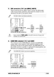
Doing so will damage the motherboard! 6 . The GAME/MIDI port on the module connects a joystick or a game pad for playing games, and MIDI devices for a GAME/MIDI port. 5 . GAME/MIDI ...USB_P6USB_P6+ GND NC USB+5V USB_P7USB_P7+ GND USB+5V USB_P5USB_P5+ GND A7V400-MX SE USB56 1 A7V400-MX SE USB connectors USB78 1 Never connect a 1 3 9 4 c a b l e to the USB connectors. The USB module is purchased separately. +5V J1B2 J1CY GND GND J1CX J1B1 +5V A7V400-MX SE GAME A7V400-MX SE Game connector ASUS A7V400-MX SE MIDI_IN J2B2 J2CY MIDI_OUT J2CX J2B1 +5V 1-23 The GAME/MIDI ...
Doing so will damage the motherboard! 6 . The GAME/MIDI port on the module connects a joystick or a game pad for playing games, and MIDI devices for a GAME/MIDI port. 5 . GAME/MIDI ...USB_P6USB_P6+ GND NC USB+5V USB_P7USB_P7+ GND USB+5V USB_P5USB_P5+ GND A7V400-MX SE USB56 1 A7V400-MX SE USB connectors USB78 1 Never connect a 1 3 9 4 c a b l e to the USB connectors. The USB module is purchased separately. +5V J1B2 J1CY GND GND J1CX J1B1 +5V A7V400-MX SE GAME A7V400-MX SE Game connector ASUS A7V400-MX SE MIDI_IN J2B2 J2CY MIDI_OUT J2CX J2B1 +5V 1-23 The GAME/MIDI ...


