Motherboard DIY Troubleshooting Guide
Page 5
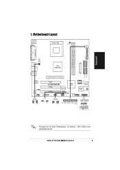
... LAN_USB34 VIA KM400A Top:Line In Center:Line Out Below:Mic In Accelerated Graphics Port (AGP1) VIA VT6103 SPDIF AD1888 FP_AUDIO PCI1 A7V400-MX SE PCI2 CR2032 3V Lithium Cell CMOS Power VIA VT8237 PCI3 CLRTC USBPWR56 USBPWR78 SB_PWR AUX CD USB56 USB78 2Mbit ISA BIOS SATA2 SATA1 ... +5V Ground Ground Speaker PANEL PLED SPEAKER HD_LED+ HD_LEDExtSMI# Ground PWRBIN Ground Reset Ground RESET HDLED PWRBTN SMI * Requires an ATX power supply. ASUS A7V400-MX SE-Motherboard 5 Prozessoren mit einer Taktfrequenz von kleiner 1 GHz dürfen nicht verwendet werden. Deutsch 1.
... LAN_USB34 VIA KM400A Top:Line In Center:Line Out Below:Mic In Accelerated Graphics Port (AGP1) VIA VT6103 SPDIF AD1888 FP_AUDIO PCI1 A7V400-MX SE PCI2 CR2032 3V Lithium Cell CMOS Power VIA VT8237 PCI3 CLRTC USBPWR56 USBPWR78 SB_PWR AUX CD USB56 USB78 2Mbit ISA BIOS SATA2 SATA1 ... +5V Ground Ground Speaker PANEL PLED SPEAKER HD_LED+ HD_LEDExtSMI# Ground PWRBIN Ground Reset Ground RESET HDLED PWRBTN SMI * Requires an ATX power supply. ASUS A7V400-MX SE-Motherboard 5 Prozessoren mit einer Taktfrequenz von kleiner 1 GHz dürfen nicht verwendet werden. Deutsch 1.
Motherboard DIY Troubleshooting Guide
Page 8
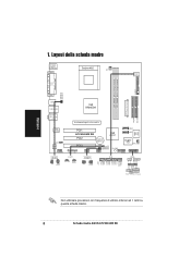
... PRI_IDE SEC_IDE USB12 LAN_USB34 VIA KM400A Top:Line In Center:Line Out Below:Mic In Accelerated Graphics Port (AGP1) VIA VT6103 SPDIF AD1888 FP_AUDIO PCI1 A7V400-MX SE PCI2 CR2032 3V Lithium Cell CMOS Power VIA VT8237 PCI3 CLRTC USBPWR56 USBPWR78 SB_PWR AUX CD USB56 USB78 2Mbit ISA BIOS SATA2 SATA1 Super I/O CHA_FAN1... HDLED PWRBTN SMI * Requires an ATX power supply. Italiano Non utilizzare processori con frequenze di utilizzo inferiori ad 1 GHz su questa scheda madre. 8 Scheda madre ASUS A7V400-MX SE
... PRI_IDE SEC_IDE USB12 LAN_USB34 VIA KM400A Top:Line In Center:Line Out Below:Mic In Accelerated Graphics Port (AGP1) VIA VT6103 SPDIF AD1888 FP_AUDIO PCI1 A7V400-MX SE PCI2 CR2032 3V Lithium Cell CMOS Power VIA VT8237 PCI3 CLRTC USBPWR56 USBPWR78 SB_PWR AUX CD USB56 USB78 2Mbit ISA BIOS SATA2 SATA1 Super I/O CHA_FAN1... HDLED PWRBTN SMI * Requires an ATX power supply. Italiano Non utilizzare processori con frequenze di utilizzo inferiori ad 1 GHz su questa scheda madre. 8 Scheda madre ASUS A7V400-MX SE
A7V400-MX SE user's manual for English version
Page 12
VIA KM400A and VT8237 The VIA KM400A Northbridge and the VIA VT8237 Southbridge chipset provides support for buying an ASUS® A7V400-MX SE motherboard! Thank you start installing the motherboard, and hardware devices on it another standout in your package with the list below.... allowing efficient execution of the above items is damaged or missing, contact your motherboard package for the following items. Motherboard ASUS A7V400-MX SE motherboard Cables Serial ATA signal cable and Serial ATA power cable Ultra DMA 133/100/66 cable Floppy disk drive cable Accessories I/O shield...
VIA KM400A and VT8237 The VIA KM400A Northbridge and the VIA VT8237 Southbridge chipset provides support for buying an ASUS® A7V400-MX SE motherboard! Thank you start installing the motherboard, and hardware devices on it another standout in your package with the list below.... allowing efficient execution of the above items is damaged or missing, contact your motherboard package for the following items. Motherboard ASUS A7V400-MX SE motherboard Cables Serial ATA signal cable and Serial ATA power cable Ultra DMA 133/100/66 cable Floppy disk drive cable Accessories I/O shield...
A7V400-MX SE user's manual for English version
Page 13
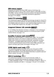
... for details. USB 2.0 technology The motherboard implements the Universal Serial Bus (USB) 2.0 specification, dramatically increasing the connection speed from the 12 Mbps bandwidth on USB 2.0. ASUS A7V400-MX SE 1-3 SoundMAX Digital Audio System can output 5.1 channel surround sound and features state-of system memory using DDR 333/266/ 200 DIMMs. The fast 333 MHz...
... for details. USB 2.0 technology The motherboard implements the Universal Serial Bus (USB) 2.0 specification, dramatically increasing the connection speed from the 12 Mbps bandwidth on USB 2.0. ASUS A7V400-MX SE 1-3 SoundMAX Digital Audio System can output 5.1 channel surround sound and features state-of system memory using DDR 333/266/ 200 DIMMs. The fast 333 MHz...

A7V400-MX SE user's manual for English version
Page 15
... install or remove any component, ensure that the ATX power supply is ON, in sleep mode, or in any motherboard component. A7V400-MX SE A7V400-MX SE Onboard LED SB_PWR ON Standby Power OFF Powered Off ASUS A7V400-MX SE 1-5 1.4 Before you proceed Take note of the onboard LED. Onboard LED The motherboard comes with a standby power LED that lights...
... install or remove any component, ensure that the ATX power supply is ON, in sleep mode, or in any motherboard component. A7V400-MX SE A7V400-MX SE Onboard LED SB_PWR ON Standby Power OFF Powered Off ASUS A7V400-MX SE 1-5 1.4 Before you proceed Take note of the onboard LED. Onboard LED The motherboard comes with a standby power LED that lights...
A7V400-MX SE user's manual for English version
Page 17
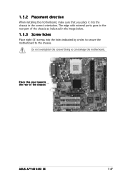
Doing so can damage the motherboard. Place this side towards the rear of the chassis as indicated in the image below. 1.5.3 Screw holes Place eight (8) screws into the chassis in the correct orientation. The edge with external ports goes to the chassis. Do not overtighten the screws! 1.5.2 Placement direction When installing the motherboard, make sure that you place it into the holes indicated by circles to secure the motherboard to the rear part of the chassis ASUS A7V400-MX SE 1-7
Doing so can damage the motherboard. Place this side towards the rear of the chassis as indicated in the image below. 1.5.3 Screw holes Place eight (8) screws into the chassis in the correct orientation. The edge with external ports goes to the chassis. Do not overtighten the screws! 1.5.2 Placement direction When installing the motherboard, make sure that you place it into the holes indicated by circles to secure the motherboard to the rear part of the chassis ASUS A7V400-MX SE 1-7
A7V400-MX SE user's manual for English version
Page 19
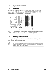
A7V400-MX SE A7V400-MX SE 184-pin DDR DIMM sockets * You can install a DDR400 DIMM(s) on the slot(s). 104 Pins 80 Pins 1.7 System memory 1.7.1 Overview The motherboard has two Double ... (DDR333). 1.7.2 Memory configurations You may only run at speeds of qualified DDR400 and DDR333 DIMM vendors. For optimum compatibility, it is double-sided. DIMM1 DIMM2 ASUS A7V400-MX SE 1-9 However, a DDR400 DIMM may install single or double-sided 64 MB, 128 MB, 256 MB, 512 MB, and 1 GB DDR DIMMs to the sockets...
A7V400-MX SE A7V400-MX SE 184-pin DDR DIMM sockets * You can install a DDR400 DIMM(s) on the slot(s). 104 Pins 80 Pins 1.7 System memory 1.7.1 Overview The motherboard has two Double ... (DDR333). 1.7.2 Memory configurations You may only run at speeds of qualified DDR400 and DDR333 DIMM vendors. For optimum compatibility, it is double-sided. DIMM1 DIMM2 ASUS A7V400-MX SE 1-9 However, a DDR400 DIMM may install single or double-sided 64 MB, 128 MB, 256 MB, 512 MB, and 1 GB DDR DIMMs to the sockets...
A7V400-MX SE user's manual for English version
Page 21
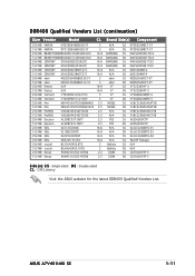
... for the latest DDR400 Qualified Vendors List. ASUS A7V400-MX SE 1-11 Single-sided D S - Double-sided C L - DDR400 Qualified Vendors List (continuation) Size Vendor Model C L Brand Side(s) Component 256 MB NANYA NT256D64S88C0G-5T 3 N/A 512 MB NANYA NT512D64S8HC0G-...
... for the latest DDR400 Qualified Vendors List. ASUS A7V400-MX SE 1-11 Single-sided D S - Double-sided C L - DDR400 Qualified Vendors List (continuation) Size Vendor Model C L Brand Side(s) Component 256 MB NANYA NT256D64S88C0G-5T 3 N/A 512 MB NANYA NT512D64S8HC0G-...
A7V400-MX SE user's manual for English version
Page 23
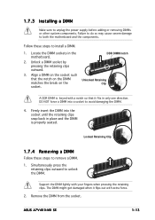
.... A DDR DIMM is properly seated. Failure to do so may cause severe damage to remove a DIMM. 1. Unlock a DIMM socket by pressing the retaining clips outward. 3. ASUS A7V400-MX SE 1-13 Locked Retaining Clip 1.7.4 Removing a DIMM Follow these steps to unlock the DIMM. 1.7.3 Installing a DIMM Make sure to avoid damaging the DIMM. 4. DDR DIMM notch...
.... A DDR DIMM is properly seated. Failure to do so may cause severe damage to remove a DIMM. 1. Unlock a DIMM socket by pressing the retaining clips outward. 3. ASUS A7V400-MX SE 1-13 Locked Retaining Clip 1.7.4 Removing a DIMM Follow these steps to unlock the DIMM. 1.7.3 Installing a DIMM Make sure to avoid damaging the DIMM. 4. DDR DIMM notch...
A7V400-MX SE user's manual for English version
Page 25
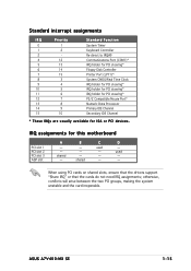
... Processor Primary IDE Channel Secondary IDE Channel * These IRQs are usually available for this motherboard PCI slot 1 PCI slot 2 PCI slot 3 AGP slot A - - shared C used - - D - B - - - ASUS A7V400-MX SE 1-15 shared - used - - - IRQ assignments for ISA or PCI devices.
... Processor Primary IDE Channel Secondary IDE Channel * These IRQs are usually available for this motherboard PCI slot 1 PCI slot 2 PCI slot 3 AGP slot A - - shared C used - - D - B - - - ASUS A7V400-MX SE 1-15 shared - used - - - IRQ assignments for ISA or PCI devices.
A7V400-MX SE user's manual for English version
Page 27
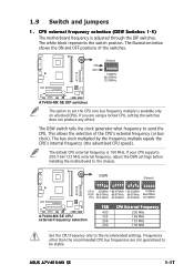
... frequencies are using a locked CPU, setting the switches does not produce any effect. A7V400-MX SE ON OFF (Default) O1 2 3 4 5 N 100MHz 66.67MHz 33.33MHz A7V400-MX SE DIP switches The option to be stable. The DSW switch tells the clock generator what...A7V400-MX SE A7V400-MX SE CPU external frequency selection FSB 400 333 266 200 CPU External Frequency 200 MHz 166 MHz 133 MHz 100 MHz Set the CPU frequency only to send the CPU. If your CPU supports 200/166/133 MHz external frequency, adjust the DSW settings before installing the motherboard to the chassis. ASUS A7V400-MX SE...
... frequencies are using a locked CPU, setting the switches does not produce any effect. A7V400-MX SE ON OFF (Default) O1 2 3 4 5 N 100MHz 66.67MHz 33.33MHz A7V400-MX SE DIP switches The option to be stable. The DSW switch tells the clock generator what...A7V400-MX SE A7V400-MX SE CPU external frequency selection FSB 400 333 266 200 CPU External Frequency 200 MHz 166 MHz 133 MHz 100 MHz Set the CPU frequency only to send the CPU. If your CPU supports 200/166/133 MHz external frequency, adjust the DSW settings before installing the motherboard to the chassis. ASUS A7V400-MX SE...
A7V400-MX SE user's manual for English version
Page 29
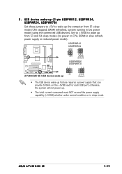
...consumed must NOT exceed the power supply capability (+5VSB) whether under normal condition or in low power mode) using the connected USB devices. ASUS A7V400-MX SE 1-19 otherwise, the system will not power up (3-pin USBPWR12, USBPWR34, USBPWR56, USBPWR78) Set these jumpers to +5V to CPU,... DRAM in slow refresh, power supply in reduced power mode). USBPWR12 USBPWR34 2 1 +5V 3 2 +5VSB (Default) USBPWR56 USBPWR78 A7V400-MX SE 12 23 +5V A7V400-MX SE USB device wake up +5VSB (Default) • The USB device wake-up the computer from S1 sleep mode (CPU stopped, DRAM refreshed...
...consumed must NOT exceed the power supply capability (+5VSB) whether under normal condition or in low power mode) using the connected USB devices. ASUS A7V400-MX SE 1-19 otherwise, the system will not power up (3-pin USBPWR12, USBPWR34, USBPWR56, USBPWR78) Set these jumpers to +5V to CPU,... DRAM in slow refresh, power supply in reduced power mode). USBPWR12 USBPWR34 2 1 +5V 3 2 +5VSB (Default) USBPWR56 USBPWR78 A7V400-MX SE 12 23 +5V A7V400-MX SE USB device wake up +5VSB (Default) • The USB device wake-up the computer from S1 sleep mode (CPU stopped, DRAM refreshed...

A7V400-MX SE user's manual for English version
Page 31
Insert one end of the cable to this connector, then connect the other end to PIN 1. A7V400-MX SE A7V400-MX SE IDE connectors ASUS A7V400-MX SE PRI_IDE SEC_IDE NOTE: Orient the red markings (usually zigzag) on the Ultra DMA cable connector. PIN 1 1-21 1.10.2 Internal connectors 1 . Refer to ...drive), and a gray connector for the jumper settings. • Pin 20 on the IDE connector is for an Ultra DMA 133 signal cable. A7V400-MX SE PIN 1 A7V400-MX SE Floppy disk drive connector 2 . If you install two hard disk drives, you connect the IDE cable. • Use the 80-conductor IDE cable...
Insert one end of the cable to this connector, then connect the other end to PIN 1. A7V400-MX SE A7V400-MX SE IDE connectors ASUS A7V400-MX SE PRI_IDE SEC_IDE NOTE: Orient the red markings (usually zigzag) on the Ultra DMA cable connector. PIN 1 1-21 1.10.2 Internal connectors 1 . Refer to ...drive), and a gray connector for the jumper settings. • Pin 20 on the IDE connector is for an Ultra DMA 133 signal cable. A7V400-MX SE PIN 1 A7V400-MX SE Floppy disk drive connector 2 . If you install two hard disk drives, you connect the IDE cable. • Use the 80-conductor IDE cable...
A7V400-MX SE user's manual for English version
Page 33
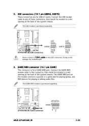
...at the back of the system chassis. USB+5V USB_P8USB_P8+ GND NC USB+5V USB_P6USB_P6+ GND NC USB+5V USB_P7USB_P7+ GND USB+5V USB_P5USB_P5+ GND A7V400-MX SE USB56 1 A7V400-MX SE USB connectors USB78 1 Never connect a 1 3 9 4 c a b l e to a slot opening at the back of the system chassis. ...will damage the motherboard! 6 . The USB module is purchased separately. +5V J1B2 J1CY GND GND J1CX J1B1 +5V A7V400-MX SE GAME A7V400-MX SE Game connector ASUS A7V400-MX SE MIDI_IN J2B2 J2CY MIDI_OUT J2CX J2B1 +5V 1-23 Connect the USB module cable to any of these connectors, then install...
...at the back of the system chassis. USB+5V USB_P8USB_P8+ GND NC USB+5V USB_P6USB_P6+ GND NC USB+5V USB_P7USB_P7+ GND USB+5V USB_P5USB_P5+ GND A7V400-MX SE USB56 1 A7V400-MX SE USB connectors USB78 1 Never connect a 1 3 9 4 c a b l e to a slot opening at the back of the system chassis. ...will damage the motherboard! 6 . The USB module is purchased separately. +5V J1B2 J1CY GND GND J1CX J1B1 +5V A7V400-MX SE GAME A7V400-MX SE Game connector ASUS A7V400-MX SE MIDI_IN J2B2 J2CY MIDI_OUT J2CX J2B1 +5V 1-23 Connect the USB module cable to any of these connectors, then install...
A7V400-MX SE user's manual for English version
Page 35
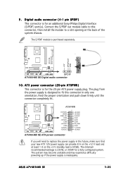
... COM +3.3VDC +3.3VDC +5.0VDC +5.0VDC -5.0VDC COM COM COM PS_ON# COM -12.0VDC +3.3VDC A7V400-MX SE ATX power connector If you will need to replace the power supply in only one orientation. The system...minimum recommended wattage is inadequate. The plug from the power supply is purchased separately. +5V SPDIFOUT GND A7V400-MX SE SPDIF A7V400-MX SE Digital audio connector 10. Find the proper orientation and push down firmly until the connector completely fit. Connect... is designed to a slot opening at least 1 A on the +5 V standby lead (+5VSB). 9 . ASUS A7V400-MX SE 1-25
... COM +3.3VDC +3.3VDC +5.0VDC +5.0VDC -5.0VDC COM COM COM PS_ON# COM -12.0VDC +3.3VDC A7V400-MX SE ATX power connector If you will need to replace the power supply in only one orientation. The system...minimum recommended wattage is inadequate. The plug from the power supply is purchased separately. +5V SPDIFOUT GND A7V400-MX SE SPDIF A7V400-MX SE Digital audio connector 10. Find the proper orientation and push down firmly until the connector completely fit. Connect... is designed to a slot opening at least 1 A on the +5 V standby lead (+5VSB). 9 . ASUS A7V400-MX SE 1-25
A7V400-MX SE user's manual for English version
Page 39
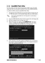
... down the computer during the updating process. The computer returns to the bootable floppy disk you created earlier. Boot the computer from the ASUS website. SST 39SF020 /5V DATE: 01/06/2005 File Name to Program : a7v4se02.bin Message: Please Wait! 5. SST 39SF020 /...verification, the utility updates the BIOS file. Copy the AWDFLASH.EXE utility from the support CD to avoid loading a wrong BIOS file. 2. ASUS A7V400-MX SE 2-3 2.1.2 AwardBIOS Flash Utility You may update the Basic Input/Output System (BIOS) using the AwardBIOS Flash Utility: 1. Save only the updated...
... down the computer during the updating process. The computer returns to the bootable floppy disk you created earlier. Boot the computer from the ASUS website. SST 39SF020 /5V DATE: 01/06/2005 File Name to Program : a7v4se02.bin Message: Please Wait! 5. SST 39SF020 /...verification, the utility updates the BIOS file. Copy the AWDFLASH.EXE utility from the support CD to avoid loading a wrong BIOS file. 2. ASUS A7V400-MX SE 2-3 2.1.2 AwardBIOS Flash Utility You may update the Basic Input/Output System (BIOS) using the AwardBIOS Flash Utility: 1. Save only the updated...
A7V400-MX SE user's manual for English version
Page 41
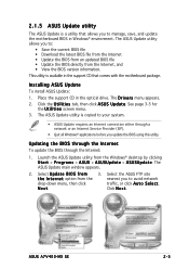
...U p d a t e. N e x t. The ASUS Update utility is a utility that comes with the motherboard package. 2.1.5 ASUS Update utility The ASUS Update is copied to your system. • ASUS Update requires an Internet connection either through the Internet: 1. ...ASUS Update utility allows you update the BIOS using this utility. This utility is available in the optical drive. Launch the ASUS Update utility from the nearest you to manage, save, and update the motherboard BIOS in Windows® environment. ASUS A7V400-MX SE 2-5 Installing ASUS Update To install ASUS...
...U p d a t e. N e x t. The ASUS Update utility is a utility that comes with the motherboard package. 2.1.5 ASUS Update utility The ASUS Update is copied to your system. • ASUS Update requires an Internet connection either through the Internet: 1. ...ASUS Update utility allows you update the BIOS using this utility. This utility is available in the optical drive. Launch the ASUS Update utility from the nearest you to manage, save, and update the motherboard BIOS in Windows® environment. ASUS A7V400-MX SE 2-5 Installing ASUS Update To install ASUS...
A7V400-MX SE user's manual for English version
Page 43
... your computer in an endless loop One long beep followed by three short beeps High frequency beeps when system is designed to make your BIOS." ASUS A7V400-MX SE 2-7 This section explains how to run this program. Even if you are installing a motherboard, reconfiguring your system using the BIOS Setup program so that you...
... your computer in an endless loop One long beep followed by three short beeps High frequency beeps when system is designed to make your BIOS." ASUS A7V400-MX SE 2-7 This section explains how to run this program. Even if you are installing a motherboard, reconfiguring your system using the BIOS Setup program so that you...
A7V400-MX SE user's manual for English version
Page 45
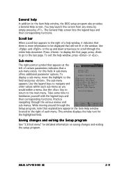
... menu by simply pressing . Saving changes and exiting the Setup program See "2.8 Exit menu" for detailed information on saving changes and exiting the setup program. ASUS A7V400-MX SE 2-9 You may launch this field. Use the key to return to the field and press . Scroll bar When a scroll bar appears to the right of...
... menu by simply pressing . Saving changes and exiting the Setup program See "2.8 Exit menu" for detailed information on saving changes and exiting the setup program. ASUS A7V400-MX SE 2-9 You may launch this field. Use the key to return to the field and press . Scroll bar When a scroll bar appears to the right of...
A7V400-MX SE user's manual for English version
Page 47
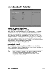
... installed or if you have the correct configuration information supplied by the drive manufacturer. In these cases, select [Manual] to recognize the installed hard disk. ASUS A7V400-MX SE 2-11 Select [CHS] in coordination with the [Manual] setting of the Primary IDE Master in the correct values for the remaining fields on a previous system...
... installed or if you have the correct configuration information supplied by the drive manufacturer. In these cases, select [Manual] to recognize the installed hard disk. ASUS A7V400-MX SE 2-11 Select [CHS] in coordination with the [Manual] setting of the Primary IDE Master in the correct values for the remaining fields on a previous system...


