Motherboard DIY Troubleshooting Guide
Page 1
® A7PRO JumperFree™ PC133/VC133 200MHz FSB AGP Pro/4X Socket A Motherboard USER'S MANUAL
® A7PRO JumperFree™ PC133/VC133 200MHz FSB AGP Pro/4X Socket A Motherboard USER'S MANUAL
Motherboard DIY Troubleshooting Guide
Page 4
... 4.1 Managing and Updating Your BIOS 47 4.1.1 Upon First Use of the Computer System 47 4.1.2 Updating BIOS Procedures 48 4 ASUS A7PRO User's Manual CONTENTS 1. HARDWARE SETUP 14 3.1 Motherboard Layout 14 3.2 Layout Contents 15 3.3 Hardware Setup Procedure 17 3.4 Motherboard Settings 17 3.5 System Memory (DIMM 25 3.5.1 General DIMM Notes 25 3.5.2 Memory Installation 26 3.6 Central Processing Unit (CPU...
... 4.1 Managing and Updating Your BIOS 47 4.1.1 Upon First Use of the Computer System 47 4.1.2 Updating BIOS Procedures 48 4 ASUS A7PRO User's Manual CONTENTS 1. HARDWARE SETUP 14 3.1 Motherboard Layout 14 3.2 Layout Contents 15 3.3 Hardware Setup Procedure 17 3.4 Motherboard Settings 17 3.5 System Memory (DIMM 25 3.5.1 General DIMM Notes 25 3.5.2 Memory Installation 26 3.6 Central Processing Unit (CPU...
Motherboard DIY Troubleshooting Guide
Page 5
APPENDIX 97 7.1 PCI-L101 Fast Ethernet Card 97 7.2 Modem Riser 99 7.3 Glossary 101 ASUS A7PRO User's Manual 5 SOFTWARE REFERENCE 87 6.1 ASUS PC Probe 87 6.2 CyberLink PowerPlayer SE 92 6.3 CyberLink PowerDVD 92 6.4 CyberLink VideoLive Mail 94 7. CONTENTS 4.2 BIOS Setup Program 51 4.2.1 BIOS Menu Bar 52 4.2.2 Legend Bar ... 4.5.1 Power Up Control 76 4.5.2 Hardware Monitor 78 4.6 Boot Menu 79 4.7 Exit Menu 81 5. SOFTWARE SETUP 83 5.1 Install Operating System 83 5.2 Start Windows 83 5.3 A7 Series Motherboard Support CD 84 5.4 Uninstalling Programs 85 6.
APPENDIX 97 7.1 PCI-L101 Fast Ethernet Card 97 7.2 Modem Riser 99 7.3 Glossary 101 ASUS A7PRO User's Manual 5 SOFTWARE REFERENCE 87 6.1 ASUS PC Probe 87 6.2 CyberLink PowerPlayer SE 92 6.3 CyberLink PowerDVD 92 6.4 CyberLink VideoLive Mail 94 7. CONTENTS 4.2 BIOS Setup Program 51 4.2.1 BIOS Menu Bar 52 4.2.2 Legend Bar ... 4.5.1 Power Up Control 76 4.5.2 Hardware Monitor 78 4.6 Boot Menu 79 4.7 Exit Menu 81 5. SOFTWARE SETUP 83 5.1 Install Operating System 83 5.2 Start Windows 83 5.3 A7 Series Motherboard Support CD 84 5.4 Uninstalling Programs 85 6.
Motherboard DIY Troubleshooting Guide
Page 7
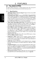
... / UltraDMA/66 (also compatible with drivers and utilities (1) This Motherboard User's Manual ASUS A7PRO User's Manual 7 FEATURES 3. 1. INTRODUCTION 1.1 How This Manual Is Organized This manual is complete. BIOS SETUP 5. APPENDIX Manual information and checklist Production information and specifications Intructions on setting up the motherboard. INTRODUCTION Manual / Checklist 1. If you discover damaged or missing items...
... / UltraDMA/66 (also compatible with drivers and utilities (1) This Motherboard User's Manual ASUS A7PRO User's Manual 7 FEATURES 3. 1. INTRODUCTION 1.1 How This Manual Is Organized This manual is complete. BIOS SETUP 5. APPENDIX Manual information and checklist Production information and specifications Intructions on setting up the motherboard. INTRODUCTION Manual / Checklist 1. If you discover damaged or missing items...
Motherboard DIY Troubleshooting Guide
Page 8
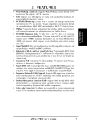
... PCI 2.2. VC SDRAM is carefully designed for 5 PCI masters. FEATURES 2.1 The ASUS A7PRO The ASUS A7PRO motherboard is a new DRAM core architecture that support four ATA66/33 devices on two channels. Appendix). 8 ASUS A7PRO User's Manual complies with support for the value-conscious PC user who wants advanced .... • JumperFree™ Mode: Adjust processor frequency settings and makes overclocking and Vcore voltage control easy, all through an optional ASUS PCI-L101 10/100 Fast Ethernet PCI card (see 7. USB controller with root hub and four function ports. • PC133 ...
... PCI 2.2. VC SDRAM is carefully designed for 5 PCI masters. FEATURES 2.1 The ASUS A7PRO The ASUS A7PRO motherboard is a new DRAM core architecture that support four ATA66/33 devices on two channels. Appendix). 8 ASUS A7PRO User's Manual complies with support for the value-conscious PC user who wants advanced .... • JumperFree™ Mode: Adjust processor frequency settings and makes overclocking and Vcore voltage control easy, all through an optional ASUS PCI-L101 10/100 Fast Ethernet PCI card (see 7. USB controller with root hub and four function ports. • PC133 ...
Motherboard DIY Troubleshooting Guide
Page 9
...: Concurrent PCI allows multiple PCI transfers from PCI master busses to meet PC 99 compliancy, major connectors in this motherboard are color-coded. 2. ASUS A7PRO User's Manual 9 FEA TURES Specifications 2. Power supply is used to physically transport commands and information between SMBus devices... gadgets, or an optional remote controller. • Desktop Management Interface (DMI): Supports DMI through the onboard hardware ASUS ASIC and the bundled ASUS PC Probe software. • SMBus: Features the System Management Bus interface, which allows hardware to communicate within a...
...: Concurrent PCI allows multiple PCI transfers from PCI master busses to meet PC 99 compliancy, major connectors in this motherboard are color-coded. 2. ASUS A7PRO User's Manual 9 FEA TURES Specifications 2. Power supply is used to physically transport commands and information between SMBus devices... gadgets, or an optional remote controller. • Desktop Management Interface (DMI): Supports DMI through the onboard hardware ASUS ASIC and the bundled ASUS PC Probe software. • SMBus: Features the System Management Bus interface, which allows hardware to communicate within a...
Motherboard DIY Troubleshooting Guide
Page 10
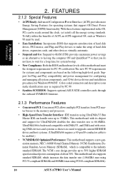
..., and Plug and Play devices to make identification easy as an alternative to be enabled.) • VCM/SDRAM Optimized Performance: This motherboard supports a new generation memory, NEC's 64Mb Virtual Channel Memory (VCM) Synchronous Dynamic Random Access Memory (SDRAM), which increases the data...8226; High-Speed Data Transfer Interface: IDE transfers using PC100-compliant SDRAMs). 10 ASUS A7PRO User's Manual 2. Color-coded connectors and descriptive icons make the setup of this motherboard meet the stringent requirements for PC 99 certification The new PC 99 requirements for ...
..., and Plug and Play devices to make identification easy as an alternative to be enabled.) • VCM/SDRAM Optimized Performance: This motherboard supports a new generation memory, NEC's 64Mb Virtual Channel Memory (VCM) Synchronous Dynamic Random Access Memory (SDRAM), which increases the data...8226; High-Speed Data Transfer Interface: IDE transfers using PC100-compliant SDRAMs). 10 ASUS A7PRO User's Manual 2. Color-coded connectors and descriptive icons make the setup of this motherboard meet the stringent requirements for PC 99 certification The new PC 99 requirements for ...
Motherboard DIY Troubleshooting Guide
Page 11
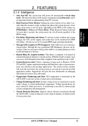
... Monitoring and Alert: System voltage levels are more critical for more memory and hard drive space to prevent possible application crashes. ASUS A7PRO User's Manual 11 2. Suggestions will give the user information on managing their computers from anywhere in the mailbox. Through the ...vital information from their limited resources more efficiently. • Temperature Monitoring and Alert: CPU temperature is monitored by the ASUS ASIC to critical motherboard components. FEA TURES Intelligence 2. All fans are set for RPM and failure. When the power button is kept in...
... Monitoring and Alert: System voltage levels are more critical for more memory and hard drive space to prevent possible application crashes. ASUS A7PRO User's Manual 11 2. Suggestions will give the user information on managing their computers from anywhere in the mailbox. Through the ...vital information from their limited resources more efficiently. • Temperature Monitoring and Alert: CPU temperature is monitored by the ASUS ASIC to critical motherboard components. FEA TURES Intelligence 2. All fans are set for RPM and failure. When the power button is kept in...
Motherboard DIY Troubleshooting Guide
Page 12
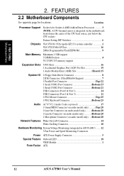
... See opposite page for Socket A AMD Athlon/Duron Processors 3 (NOTE: A CPU thermal sensor is integrated on the motherboard, located near the center of the CPU heat source, just below the CPU socket) Feature Setting DIP Switches 6 Chipsets ... 10 Hardware Monitoring System Voltage Monitoring (integrated in ASUS ASIC) ....... 12 3 Fan Power and Speed Monitoring Connectors Power ATX Power Supply Connector 5 Special Feature Onboard LED 18 VRM Module 1 Form Factor ATX 12 ASUS A7PRO User's Manual Location Processor Support Socket A for locations. FEA TURES Motherboard Parts 2.
... See opposite page for Socket A AMD Athlon/Duron Processors 3 (NOTE: A CPU thermal sensor is integrated on the motherboard, located near the center of the CPU heat source, just below the CPU socket) Feature Setting DIP Switches 6 Chipsets ... 10 Hardware Monitoring System Voltage Monitoring (integrated in ASUS ASIC) ....... 12 3 Fan Power and Speed Monitoring Connectors Power ATX Power Supply Connector 5 Special Feature Onboard LED 18 VRM Module 1 Form Factor ATX 12 ASUS A7PRO User's Manual Location Processor Support Socket A for locations. FEA TURES Motherboard Parts 2.
Motherboard DIY Troubleshooting Guide
Page 14
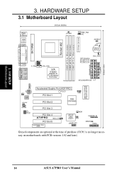
HARDWARE SETUP 3.1 Motherboard Layout 24.5cm (9.64in) PS/2 T: Mouse B: Keyboard USB T: Port0 B: Port1 COM1 01 01 01 JTPWR PWR_FAN VIO 3VSBSLT CLRTC CR2032 3V Lithium Cell CMOS Power ... USBPORT CHASSIS IR IDELED PANEL Grayed components are optional at the time of purchase (JTCPU is no longer necessary on motherboards with PCB versions 1.02 and later) 14 ASUS A7PRO User's Manual H/W SETUP Motherboard Layout Socket 462 DIMM3 (64/72 bit, 168-pin module) DIMM2 (64/72 bit, 168-pin module) DIMM1 (64/72...
HARDWARE SETUP 3.1 Motherboard Layout 24.5cm (9.64in) PS/2 T: Mouse B: Keyboard USB T: Port0 B: Port1 COM1 01 01 01 JTPWR PWR_FAN VIO 3VSBSLT CLRTC CR2032 3V Lithium Cell CMOS Power ... USBPORT CHASSIS IR IDELED PANEL Grayed components are optional at the time of purchase (JTCPU is no longer necessary on motherboards with PCB versions 1.02 and later) 14 ASUS A7PRO User's Manual H/W SETUP Motherboard Layout Socket 462 DIMM3 (64/72 bit, 168-pin module) DIMM2 (64/72 bit, 168-pin module) DIMM1 (64/72...
Motherboard DIY Troubleshooting Guide
Page 15
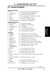
HARDWARE SETUP 3.2 Layout Contents Motherboard Settings 1) JEN p. 18 JumperFree Mode (JumperFree/Jumper Mode) 2) AUDIOCODEC p. 19 Onboard Audio Setting (Enable/Enable) 3) 3VSBSLT p. 20 PCI 3Volt Setting (3 Volt/3 VSB) 4) VIO p. 21 I/O Voltage ... 16) MIC2 p. 40 Internal Microphone Header (3 pins) 17) HPHONE p. 40 Headphone True-Level Out Header (3 pins) 18) USB3A, USB3 p. 41 USB Headers (5-1 pins / 10-1 pins) ASUS A7PRO User's Manual continued... 15 H/W SETUP Layout Contents 3. 3.
HARDWARE SETUP 3.2 Layout Contents Motherboard Settings 1) JEN p. 18 JumperFree Mode (JumperFree/Jumper Mode) 2) AUDIOCODEC p. 19 Onboard Audio Setting (Enable/Enable) 3) 3VSBSLT p. 20 PCI 3Volt Setting (3 Volt/3 VSB) 4) VIO p. 21 I/O Voltage ... 16) MIC2 p. 40 Internal Microphone Header (3 pins) 17) HPHONE p. 40 Headphone True-Level Out Header (3 pins) 18) USB3A, USB3 p. 41 USB Headers (5-1 pins / 10-1 pins) ASUS A7PRO User's Manual continued... 15 H/W SETUP Layout Contents 3. 3.
Motherboard DIY Troubleshooting Guide
Page 17
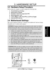
... to a safely grounded object or to change your computer. 1. Install the Central Processing Unit (CPU) 4. Install Expansion Cards 5. Computer motherboards and expansion cards contain very delicate Integrated Circuit (IC) chips. Hold components by the edges and try not to your computer when working ...pad or on the bag that you work on the motherboard. H/W SETUP Motherboard Settings 3. 3. Ensure that the system is switched off mode and not powered OFF. 01 01 01 A7PRO A7PRO Onboard LED ON Standby Power OFF Powered Off ASUS A7PRO User's Manual 17 The onboard LED when lit acts...
... to a safely grounded object or to change your computer. 1. Install the Central Processing Unit (CPU) 4. Install Expansion Cards 5. Computer motherboards and expansion cards contain very delicate Integrated Circuit (IC) chips. Hold components by the edges and try not to your computer when working ...pad or on the bag that you work on the motherboard. H/W SETUP Motherboard Settings 3. 3. Ensure that the system is switched off mode and not powered OFF. 01 01 01 A7PRO A7PRO Onboard LED ON Standby Power OFF Powered Off ASUS A7PRO User's Manual 17 The onboard LED when lit acts...
Motherboard DIY Troubleshooting Guide
Page 18
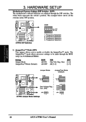
... JumperFree Mode (Default) DSW 4321 OFF ON ON See Voltage Reg. Out. (VID) A7PRO JEN 12 A7PRO Jumper Mode Settings DSW 4321 OFF ON ON 1234 VID4 VID3 VID2 VID1 JEN 23 18 ASUS A7PRO User's Manual The white block represents the switch's position. The example below shows all the... switches in the OFF position. 01 01 01 01 01 01 A7PRO A7PRO DIP Switches DSW 4 321 OFF ON ON 1. 3. HARDWARE SETUP Motherboard Features Settings (DIP Switches - ...
... JumperFree Mode (Default) DSW 4321 OFF ON ON See Voltage Reg. Out. (VID) A7PRO JEN 12 A7PRO Jumper Mode Settings DSW 4321 OFF ON ON 1234 VID4 VID3 VID2 VID1 JEN 23 18 ASUS A7PRO User's Manual The white block represents the switch's position. The example below shows all the... switches in the OFF position. 01 01 01 01 01 01 A7PRO A7PRO DIP Switches DSW 4 321 OFF ON ON 1. 3. HARDWARE SETUP Motherboard Features Settings (DIP Switches - ...
Motherboard DIY Troubleshooting Guide
Page 19
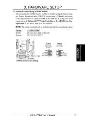
... PCI audio card on any of the expansion slots or a primary AMR on motherboards with the onboard audio option. NOTE: This setting is available only on the AMR slot. Setting Enable Disable AUDIOCODEC [1-2] [1-2] [1-2] [1-2] (default) [2-3] [2-3] [2-3] [2-3] 01 01 01 A7PRO A7PRO Audio Codec Setting Enable Onboard Audio Codec (Default) 12 SPK ADN# AUD_EN2 AUD_EN1... CODEC may be enabled or disabled using a PCI audio expansion card, Onboard AC'97 Audio Controller in 4.4.2 I/O Device Configuration of these jumpers. H/W SETUP Motherboard Settings ASUS A7PRO User's Manual 19 3.
... PCI audio card on any of the expansion slots or a primary AMR on motherboards with the onboard audio option. NOTE: This setting is available only on the AMR slot. Setting Enable Disable AUDIOCODEC [1-2] [1-2] [1-2] [1-2] (default) [2-3] [2-3] [2-3] [2-3] 01 01 01 A7PRO A7PRO Audio Codec Setting Enable Onboard Audio Codec (Default) 12 SPK ADN# AUD_EN2 AUD_EN1... CODEC may be enabled or disabled using a PCI audio expansion card, Onboard AC'97 Audio Controller in 4.4.2 I/O Device Configuration of these jumpers. H/W SETUP Motherboard Settings ASUS A7PRO User's Manual 19 3.
Motherboard DIY Troubleshooting Guide
Page 20
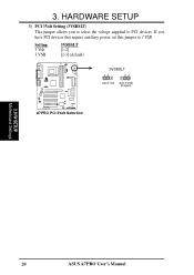
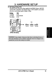
3. H/W SETUP Motherboard Settings 20 ASUS A7PRO User's Manual Setting 3 Volt 3 VSB 3VSBSLT [1-2] [2-3] (default) 01 01 01 3VSBSLT 12 23 Add 3 Volt Add 3 VSB (Default) A7PRO A7PRO PCI 3Volt Selection 3. If you to select the voltage supplied to 3 VSB. HARDWARE SETUP 3) PCI 3Volt Setting (3VSBSLT) This jumper allows you have PCI devices that require auxiliary power, set this jumper to PCI devices.
3. H/W SETUP Motherboard Settings 20 ASUS A7PRO User's Manual Setting 3 Volt 3 VSB 3VSBSLT [1-2] [2-3] (default) 01 01 01 3VSBSLT 12 23 Add 3 Volt Add 3 VSB (Default) A7PRO A7PRO PCI 3Volt Selection 3. If you to select the voltage supplied to 3 VSB. HARDWARE SETUP 3) PCI 3Volt Setting (3VSBSLT) This jumper allows you have PCI devices that require auxiliary power, set this jumper to PCI devices.
Motherboard DIY Troubleshooting Guide
Page 21
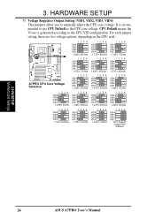
... the CPU's I/O buffer. Setting 3.30 Volt 3.45 Volt Test Mode VIO [1-2] [2-3] (default) [3-4] 01 01 01 12 3.30 Volt VIO 23 34 3.45 Volt Test Mode A7PRO A7PRO VIO Setting WARNING! 3. HARDWARE SETUP 4) I/O Voltage Setting (VIO) VIO allows you leave this setting on its default. 3. H/W SETUP Motherboard Settings ASUS A7PRO User's Manual 21
... the CPU's I/O buffer. Setting 3.30 Volt 3.45 Volt Test Mode VIO [1-2] [2-3] (default) [3-4] 01 01 01 12 3.30 Volt VIO 23 34 3.45 Volt Test Mode A7PRO A7PRO VIO Setting WARNING! 3. HARDWARE SETUP 4) I/O Voltage Setting (VIO) VIO allows you leave this setting on its default. 3. H/W SETUP Motherboard Settings ASUS A7PRO User's Manual 21

Motherboard DIY Troubleshooting Guide
Page 22
... 4321 4321 ON ON ON ON CPU 107.00 MHz 109.00 MHz 110.00 MHz 111.00 MHz A7PRO PCI 35.67 MHz 36.33 MHz 36.67 MHz 37.00 MHz A7PRO CPU External Frequency Selection 4321 4321 4321 4321 ON ON ON ON CPU 113.00 MHz 115.00....30 MHz PCI 37.67 MHz 39.33 MHz 39.00 MHz 33.33 MHz IMPORTANT: 1. Otherwise, if JumperFree mode is not recommended. H/W SETUP Motherboard Settings 22 ASUS A7PRO User's Manual It may result in a slower speed and premature wearing of these switches (set Operating Frequency Setting to Jumper Mode: [1-2]; [See section 1]. 2. WARNING...
... 4321 4321 ON ON ON ON CPU 107.00 MHz 109.00 MHz 110.00 MHz 111.00 MHz A7PRO PCI 35.67 MHz 36.33 MHz 36.67 MHz 37.00 MHz A7PRO CPU External Frequency Selection 4321 4321 4321 4321 ON ON ON ON CPU 113.00 MHz 115.00....30 MHz PCI 37.67 MHz 39.33 MHz 39.00 MHz 33.33 MHz IMPORTANT: 1. Otherwise, if JumperFree mode is not recommended. H/W SETUP Motherboard Settings 22 ASUS A7PRO User's Manual It may result in a slower speed and premature wearing of these switches (set Operating Frequency Setting to Jumper Mode: [1-2]; [See section 1]. 2. WARNING...
Motherboard DIY Troubleshooting Guide
Page 23
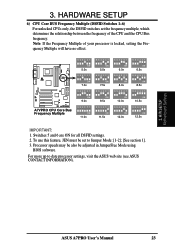
... set the frequency multiple, which determines the relationship between the frequency of your processor is locked, setting the Frequency Multiple will have no effect. H/W SETUP Motherboard Settings ASUS A7PRO User's Manual 23 For more up to Jumper Mode: [1-2]; [See section 1]. 3. 3. HARDWARE SETUP 6) CPU Core BUS Frequency Multiple (DSFID Switches 1-6) For unlocked CPUs only...
... set the frequency multiple, which determines the relationship between the frequency of your processor is locked, setting the Frequency Multiple will have no effect. H/W SETUP Motherboard Settings ASUS A7PRO User's Manual 23 For more up to Jumper Mode: [1-2]; [See section 1]. 3. 3. HARDWARE SETUP 6) CPU Core BUS Frequency Multiple (DSFID Switches 1-6) For unlocked CPUs only...
Motherboard DIY Troubleshooting Guide
Page 24
... VID1 1.725/1.75Volts 1234 VID4 VID3 VID2 VID1 1.675/1.70Volts 1234 VID4 VID3 VID2 VID1 1.625/1.65Volts 1234 VID4 VID3 VID2 VID1 1.575/1.60Volts A7PRO A7PRO CPU Core Voltage Selection 1234 VID4 VID3 VID2 VID1 1.525/1.55Volts 1234 VID4 VID3 VID2 VID1 1.475/1.50Volts 1234 VID4 VID3 VID2 VID1 1.425/1.45Volts...20Volts 1234 VID4 VID3 VID2 VID1 1.125/1.15Volts 1234 VID4 VID3 VID2 VID1 1.075/1.10Volts 1234 VID4 VID3 VID2 VID1 CPU Default/ JumperFree (Default) 3. H/W SETUP Motherboard Settings 24 ASUS A7PRO User's Manual It is generated according to manually adjust the CPU core voltage.
... VID1 1.725/1.75Volts 1234 VID4 VID3 VID2 VID1 1.675/1.70Volts 1234 VID4 VID3 VID2 VID1 1.625/1.65Volts 1234 VID4 VID3 VID2 VID1 1.575/1.60Volts A7PRO A7PRO CPU Core Voltage Selection 1234 VID4 VID3 VID2 VID1 1.525/1.55Volts 1234 VID4 VID3 VID2 VID1 1.475/1.50Volts 1234 VID4 VID3 VID2 VID1 1.425/1.45Volts...20Volts 1234 VID4 VID3 VID2 VID1 1.125/1.15Volts 1234 VID4 VID3 VID2 VID1 1.075/1.10Volts 1234 VID4 VID3 VID2 VID1 CPU Default/ JumperFree (Default) 3. H/W SETUP Motherboard Settings 24 ASUS A7PRO User's Manual It is generated according to manually adjust the CPU core voltage.
Motherboard DIY Troubleshooting Guide
Page 25
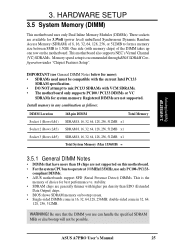
.... double-sided come in 16, 32, 64,128, 256MB; Be sure that have more ): • SDRAMs used must be possible. ASUS A7PRO User's Manual 25 One side (with VCM SDRAMs. • The motherboard only supports PC100 / PC133 DIMMs or VC SDRAMs for more than EDO (Extended Data Output) chips. • BIOS shows SDRAM...
.... double-sided come in 16, 32, 64,128, 256MB; Be sure that have more ): • SDRAMs used must be possible. ASUS A7PRO User's Manual 25 One side (with VCM SDRAMs. • The motherboard only supports PC100 / PC133 DIMMs or VC SDRAMs for more than EDO (Extended Data Output) chips. • BIOS shows SDRAM...


