Owner's Manual
Page 4
...outlet, even if this unit itself is connected to this unit near the AC outlet and where the AC power plug can cause hearing loss. Yamaha will not be held responsible for any damage resulting from the wall outlet. 16 Install this unit, and/or personal injury. vacation), disconnect the...unit is designed to consume a very small quantity of plug to hot, and do not locate this unit. Contact qualified Yamaha service personnel when any reasons. 15 When not planning to set for any service is called the standby mode. Cet appareil numérique de la classe B est conforme à...
...outlet, even if this unit itself is connected to this unit near the AC outlet and where the AC power plug can cause hearing loss. Yamaha will not be held responsible for any damage resulting from the wall outlet. 16 Install this unit, and/or personal injury. vacation), disconnect the...unit is designed to consume a very small quantity of plug to hot, and do not locate this unit. Contact qualified Yamaha service personnel when any reasons. 15 When not planning to set for any service is called the standby mode. Cet appareil numérique de la classe B est conforme à...
Owner's Manual
Page 5
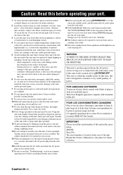
...OPTION MENU 73 Remote control features 76 Controlling this manual • y indicates a tip for your DVD player and other components.... 76 Setting remote control codes 78 Using multi-zone configuration 79 Connecting Zone 2 79 Controlling Zone 2 80 Advanced setup 82 ADDITIONAL INFORMATION Troubleshooting 84 ... HDMI 14 Audio and video signal flow 15 Connecting video components 16 Connecting other components 17 Connecting audio components 19 Connecting a Yamaha iPod™ universal dock or Bluetooth™ adapter 20 Using REMOTE IN/OUT jacks 20 Using the VIDEO AUX jacks on ...
...OPTION MENU 73 Remote control features 76 Controlling this manual • y indicates a tip for your DVD player and other components.... 76 Setting remote control codes 78 Using multi-zone configuration 79 Connecting Zone 2 79 Controlling Zone 2 80 Advanced setup 82 ADDITIONAL INFORMATION Troubleshooting 84 ... HDMI 14 Audio and video signal flow 15 Connecting video components 16 Connecting other components 17 Connecting audio components 19 Connecting a Yamaha iPod™ universal dock or Bluetooth™ adapter 20 Using REMOTE IN/OUT jacks 20 Using the VIDEO AUX jacks on ...

Owner's Manual
Page 7
...started Getting started ■ Supplied accessories Check that you received all of the batteries if you notice that lets the sound come into the AC wall outlet. Improper setting of the VOLTAGE SELECTOR may be set up the remote control code. Clean the battery compartment thoroughly..., UM-4) according to get the most importantly, without annoying blaring or distortion - Since hearing damage from loud sounds is too late, Yamaha and the Electronic Industries Association's Consumer Electronics Group recommend you to the polarity markings (+ and -) on the rear panel of batteries (...
...started Getting started ■ Supplied accessories Check that you received all of the batteries if you notice that lets the sound come into the AC wall outlet. Improper setting of the VOLTAGE SELECTOR may be set up the remote control code. Clean the battery compartment thoroughly..., UM-4) according to get the most importantly, without annoying blaring or distortion - Since hearing damage from loud sounds is too late, Yamaha and the Electronic Industries Association's Consumer Electronics Group recommend you to the polarity markings (+ and -) on the rear panel of batteries (...
Owner's Manual
Page 8
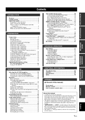
... left speaker Front right speaker Subwoofer Surround right speaker Center speaker DVD player Surround left speaker Surround back right speaker Surround back left speaker Step 1: Set up your speakers ☞ P. 5 Step 2: Connect your home theater. The minimum required speakers are two front speakers. Center speaker 3. Quick start guide Quick start guide...
... left speaker Front right speaker Subwoofer Surround right speaker Center speaker DVD player Surround left speaker Surround back right speaker Surround back left speaker Step 1: Set up your speakers ☞ P. 5 Step 2: Connect your home theater. The minimum required speakers are two front speakers. Center speaker 3. Quick start guide Quick start guide...
Owner's Manual
Page 9
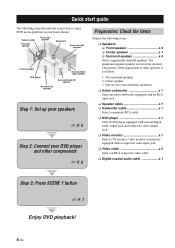
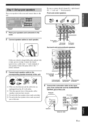
... or shaped differently, perhaps with a stripe, groove or ridge. Connect the striped (grooved, etc.) cable to this unit. INTRODUCTION Step 1: Set up your speakers Place your speakers in the room and connect them to the "+" (red) terminals of your speakers and subwoofer in the room...Surround and surround back speakers Cables are unplugged from the AC wall outlets. 2 Twist the exposed wires of this unit. Subwoofer AV receiver Input jack Subwoofer cable SUBWOOFER OUTPUT jack 5 En English COAXIAL OPTICAL SPEAKERS DVD IN1 DTV/CBL IN2 HDMI REMOTE IN OUT +12V ...
... or shaped differently, perhaps with a stripe, groove or ridge. Connect the striped (grooved, etc.) cable to this unit. INTRODUCTION Step 1: Set up your speakers Place your speakers in the room and connect them to the "+" (red) terminals of your speakers and subwoofer in the room...Surround and surround back speakers Cables are unplugged from the AC wall outlets. 2 Twist the exposed wires of this unit. Subwoofer AV receiver Input jack Subwoofer cable SUBWOOFER OUTPUT jack 5 En English COAXIAL OPTICAL SPEAKERS DVD IN1 DTV/CBL IN2 HDMI REMOTE IN OUT +12V ...
Owner's Manual
Page 10
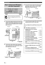
...; Connecting a DVD player ☞ P. 17 • Connecting a DVD recorder ☞ P. 18 • Connecting a set-top boxes ☞ P. 18 • Connecting a CD player and a CD recorder/ MD recorder ☞ P. 19 ...8226; Connecting a multi-format player or an external decoder ☞ P. 19 • Connecting an Yamaha iPod/Bluetooth dock ☞ P. 20 • Connecting the REMOTE IN/OUT jacks ☞ P. ...OOUUTT S S VVIIDDEEOO DOCK ANTENNA AM GND FM 75 UNBAL. Video monitor AV receiver Make sure that this unit and other components COAXIAL OOPPTTIICCAALL SPEAKERS DVD IN1 ...
...; Connecting a DVD player ☞ P. 17 • Connecting a DVD recorder ☞ P. 18 • Connecting a set-top boxes ☞ P. 18 • Connecting a CD player and a CD recorder/ MD recorder ☞ P. 19 ...8226; Connecting a multi-format player or an external decoder ☞ P. 19 • Connecting an Yamaha iPod/Bluetooth dock ☞ P. 20 • Connecting the REMOTE IN/OUT jacks ☞ P. ...OOUUTT S S VVIIDDEEOO DOCK ANTENNA AM GND FM 75 UNBAL. Video monitor AV receiver Make sure that this unit and other components COAXIAL OOPPTTIICCAALL SPEAKERS DVD IN1 ...
Owner's Manual
Page 11
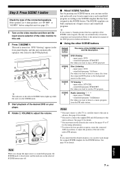
...to this unit. 2 Press TSCENE 1. input source: DVD - sound field program: STRAIGHT For when you can turn on the video monitor and then set "SP IMP." Notes *1 You must tune into the desired radio station. See page 18 for this room. This unit is turned on the selected ... SCENE template and its description DVD Viewing - The SCENE templates are 6 ohm speakers, set the input source selector of the connected speakers. input source: DVD - sound field program: 7ch Stereo For when you connect a Yamaha product that has been assigned to a music disc from the FM radio station. input ...
...to this unit. 2 Press TSCENE 1. input source: DVD - sound field program: STRAIGHT For when you can turn on the video monitor and then set "SP IMP." Notes *1 You must tune into the desired radio station. See page 18 for this room. This unit is turned on the selected ... SCENE template and its description DVD Viewing - The SCENE templates are 6 ohm speakers, set the input source selector of the connected speakers. input source: DVD - sound field program: 7ch Stereo For when you connect a Yamaha product that has been assigned to a music disc from the FM radio station. input ...

Owner's Manual
Page 12
... consumes a small amount of this unit ☞ P. 63 • Setting the remote control ☞ P. 76 • Adjusting the advanced parameters ☞ P. 82 ■ Additional features Automatically turning off this unit to receive infrared signals from the standby mode, press AMAIN ZONE ON/OFF (or ...HPOWER). See page 23 for your original SCENE templates ☞ P. 33 This unit is set this unit ☞ P. 39 8 En What do you...
... consumes a small amount of this unit ☞ P. 63 • Setting the remote control ☞ P. 76 • Adjusting the advanced parameters ☞ P. 82 ■ Additional features Automatically turning off this unit to receive infrared signals from the standby mode, press AMAIN ZONE ON/OFF (or ...HPOWER). See page 23 for your original SCENE templates ☞ P. 33 This unit is set this unit ☞ P. 39 8 En What do you...

Owner's Manual
Page 14
Connections Placing speakers The speaker layout below shows the speaker setting we recommend. The distance of each speaker from each side of the room to reduce wall reflections. 10 En Turn it to -back transitions. Best ... not only for the main source sound plus effect sounds. The position of the LFE (low-frequency effect) channel included in amplifier, such as the Yamaha Active Servo Processing Subwoofer System, is not practical to place the subwoofer near the front speakers. But it . You can do without it is not...
Connections Placing speakers The speaker layout below shows the speaker setting we recommend. The distance of each speaker from each side of the room to reduce wall reflections. 10 En Turn it to -back transitions. Best ... not only for the main source sound plus effect sounds. The position of the LFE (low-frequency effect) channel included in amplifier, such as the Yamaha Active Servo Processing Subwoofer System, is not practical to place the subwoofer near the front speakers. But it . You can do without it is not...
Owner's Manual
Page 15
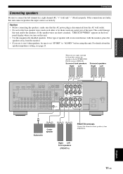
... Be sure to the left channel (L), right channel (R), "+" (red) and "-" (black) properly. This could damage this unit. For details about the speaker impedance setting, see page 23. to set "SP IMP." Right Left Front speakers (FRONT A) English 11 En If this type of speaker still creates interference with the monitor, place the...
... Be sure to the left channel (L), right channel (R), "+" (red) and "-" (black) properly. This could damage this unit. For details about the speaker impedance setting, see page 23. to set "SP IMP." Right Left Front speakers (FRONT A) English 11 En If this type of speaker still creates interference with the monitor, place the...
Owner's Manual
Page 16
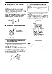
... • When you make the conventional connection, make bi-amplification connections to one speaker system. Banana plug 12 En To activate the bi-amplification connections, set "BI-AMP" to separate the LPF (low pass filter) and HPF (high pass filter) crossovers. Refer to the instruction manuals of the corresponding terminal. Check...
... • When you make the conventional connection, make bi-amplification connections to one speaker system. Banana plug 12 En To activate the bi-amplification connections, set "BI-AMP" to separate the LPF (low pass filter) and HPF (high pass filter) crossovers. Refer to the instruction manuals of the corresponding terminal. Check...
Owner's Manual
Page 19
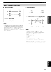
... input at the HDMI IN jacks are input at the HDMI, COMPONENT VIDEO, S VIDEO and VIDEO jacks, the priority order of the input signals is set to "Other" (see page 73) Notes • When the all video signals are not output at the HDMI IN DVD or HDMI IN DTV/ CBL...
... input at the HDMI IN jacks are input at the HDMI, COMPONENT VIDEO, S VIDEO and VIDEO jacks, the priority order of the input signals is set to "Other" (see page 73) Notes • When the all video signals are not output at the HDMI IN DVD or HDMI IN DTV/ CBL...

Owner's Manual
Page 21
...same type of this unit and other components to "ON" (see page 73), the converted video signals are unplugged from the AC wall outlets. is set to the VIDEO jacks. • When "VIDEO CONV." To record a source, make the same type of video connections between each component. •... To make a digital connection to a component other than the default component assigned to DIGITAL INPUT jack, select the corresponding setting for "OPTICAL IN" or "COAXIAL IN" in "INPUT ASSIGNMENT" (see page 71). • If you connected your TV to the VIDEO MONITOR ...
...same type of this unit and other components to "ON" (see page 73), the converted video signals are unplugged from the AC wall outlets. is set to the VIDEO jacks. • When "VIDEO CONV." To record a source, make the same type of video connections between each component. •... To make a digital connection to a component other than the default component assigned to DIGITAL INPUT jack, select the corresponding setting for "OPTICAL IN" or "COAXIAL IN" in "INPUT ASSIGNMENT" (see page 71). • If you connected your TV to the VIDEO MONITOR ...
Owner's Manual
Page 22
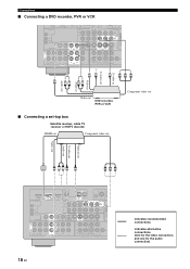
... Video in Audio in Audio out V S V RL RL S PR PB Y Video out DVD recorder, PVR or VCR Component video out ■ Connecting a set-top box Satellite receiver, cable TV receiver or HDTV decoder HDMI out Component video out Optical out S-video out Audio out Video out V LRS O PR PB Y COAXIAL OPTICAL DVD IN1...
... Video in Audio in Audio out V S V RL RL S PR PB Y Video out DVD recorder, PVR or VCR Component video out ■ Connecting a set-top box Satellite receiver, cable TV receiver or HDTV decoder HDMI out Component video out Optical out S-video out Audio out Video out V LRS O PR PB Y COAXIAL OPTICAL DVD IN1...
Owner's Manual
Page 23
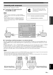
... input at least a 5.1-channel speaker system before using this unit and other than the default component assigned to each DIGITAL INPUT jack, select the corresponding setting in "INPUT ASSIGNMENT" (see page 72). CENTER L R FRONT(6CH) SB(8CH) SURROUND SUB WOOFER MULTI CH INPUT LR LR L *1 R LR CENTER L...connect at the MULTI CH INPUT jacks to accommodate for missing speakers. indicates recommended connections indicates alternative connections LR Audio in "MULTI CH SET" (see page 71). Be sure to match the left and right outputs to the left and right SURROUND and SUBWOOFER) for ...
... input at least a 5.1-channel speaker system before using this unit and other than the default component assigned to each DIGITAL INPUT jack, select the corresponding setting in "INPUT ASSIGNMENT" (see page 72). CENTER L R FRONT(6CH) SB(8CH) SURROUND SUB WOOFER MULTI CH INPUT LR LR L *1 R LR CENTER L...connect at the MULTI CH INPUT jacks to accommodate for missing speakers. indicates recommended connections indicates alternative connections LR Audio in "MULTI CH SET" (see page 71). Be sure to match the left and right outputs to the left and right SURROUND and SUBWOOFER) for ...

Owner's Manual
Page 24
... signals, this unit using its dedicated cable. Using REMOTE IN/OUT jacks When the components are unplugged from the AC wall outlets. Connect a Yamaha iPod universal dock or Bluetooth adapter to "OFF" (see page 83). 20 En Refer to the owner's manuals for details about the capability... REMOTE IN OUT +12V 15mA MAX. This unit is not the Yamaha product, set "SCENE IR" in XM PB SIRIUS DTV/CBL Y B DVR C DOCK ANTENNA AM GND SURROUND BAC R Yamaha iPod universal dock or Bluetooth adapter Infrared signal receiver or Yamaha component Yamaha component (CD or DVD player, etc.) y • If the...
... signals, this unit using its dedicated cable. Using REMOTE IN/OUT jacks When the components are unplugged from the AC wall outlets. Connect a Yamaha iPod universal dock or Bluetooth adapter to "OFF" (see page 83). 20 En Refer to the owner's manuals for details about the capability... REMOTE IN OUT +12V 15mA MAX. This unit is not the Yamaha product, set "SCENE IR" in XM PB SIRIUS DTV/CBL Y B DVR C DOCK ANTENNA AM GND SURROUND BAC R Yamaha iPod universal dock or Bluetooth adapter Infrared signal receiver or Yamaha component Yamaha component (CD or DVD player, etc.) y • If the...
Owner's Manual
Page 26
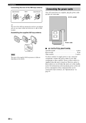
... either end of the AM loop antenna does not have any connected components. However, power to these outlet(s) is cut off when this unit is set to the standby mode. Connect the power cable of the AM loop antenna Open the lever Insert Close the lever Connecting the power cable Once...
... either end of the AM loop antenna does not have any connected components. However, power to these outlet(s) is cut off when this unit is set to the standby mode. Connect the power cable of the AM loop antenna Open the lever Insert Close the lever Connecting the power cable Once...
Owner's Manual
Page 27
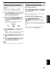
... unit. English 23 En TONE CONTROL While holding down MAIN ZONE ON/OFF 3 Press OPROGRAM l / h to use 6 ohm speakers, set "SP IMP." Note The setting you made is reflected next time you turn off the power ■ Turning on this unit Press AMAIN ZONE ON/OFF (or HPOWER) to the .... 4 Press PSTRAIGHT repeatedly to select "6Ω MIN". 5 Press AMAIN ZONE ON/OFF to save the new setting and turn on the front panel to set this unit consumes a small amount of power in order to receive infrared signals from the remote control. This unit turns on, and the advanced setup menu appears in...
... unit. English 23 En TONE CONTROL While holding down MAIN ZONE ON/OFF 3 Press OPROGRAM l / h to use 6 ohm speakers, set "SP IMP." Note The setting you made is reflected next time you turn off the power ■ Turning on this unit Press AMAIN ZONE ON/OFF (or HPOWER) to the .... 4 Press PSTRAIGHT repeatedly to select "6Ω MIN". 5 Press AMAIN ZONE ON/OFF to save the new setting and turn on the front panel to set this unit consumes a small amount of power in order to receive infrared signals from the remote control. This unit turns on, and the advanced setup menu appears in...

Owner's Manual
Page 28
... paring (see page 61) or the Bluetooth adaptor is searching the Bluetooth component (see page 61). • Lights up while the connected Yamaha Bluetooth adaptor is connected to the Bluetooth component (see page 20). 3 ENHANCER indicator Lights up when the Compressed Music Enhancer mode is selected ...at the HDMI IN jacks (see page 14). 2 DOCK indicator • Lights up when you run "AUTO SETUP" and when the speaker settings set of this unit function. A Headphone indicator Lights up when headphones are activated. Connections Front panel display Note The XM and SIRIUS indicator is ...
... paring (see page 61) or the Bluetooth adaptor is searching the Bluetooth component (see page 61). • Lights up while the connected Yamaha Bluetooth adaptor is connected to the Bluetooth component (see page 20). 3 ENHANCER indicator Lights up when the Compressed Music Enhancer mode is selected ...at the HDMI IN jacks (see page 14). 2 DOCK indicator • Lights up when you run "AUTO SETUP" and when the speaker settings set of this unit function. A Headphone indicator Lights up when headphones are activated. Connections Front panel display Note The XM and SIRIUS indicator is ...
Owner's Manual
Page 29
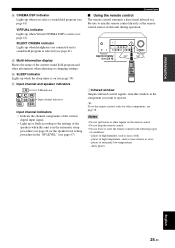
... 30º 30º 1Infrared window Outputs infrared control signals. Connections ■ Using the remote control The remote control transmits a directional infrared ray. y To set the remote control codes for other components, see page 67). Be sure to aim the remote control directly at the component you select a sound field.... Aim this window at the remote control sensor on (see page 39). PREPARATION D CINEMA DSP indicator Lights up or flash according to the settings of the speakers when this unit is in the automatic setup procedure (see page 26) or the speaker level...
... 30º 30º 1Infrared window Outputs infrared control signals. Connections ■ Using the remote control The remote control transmits a directional infrared ray. y To set the remote control codes for other components, see page 67). Be sure to aim the remote control directly at the component you select a sound field.... Aim this window at the remote control sensor on (see page 39). PREPARATION D CINEMA DSP indicator Lights up or flash according to the settings of the speakers when this unit is in the automatic setup procedure (see page 26) or the speaker level...


