Owner's Manual
Page 5
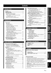
...flow 15 Connecting video components 16 Connecting other components 17 Connecting audio components 19 Connecting a Yamaha iPod™ universal dock or Bluetooth™ adapter 20 Using REMOTE IN/OUT jacks 20 Using the VIDEO AUX jacks on the front panel .... 21 Connecting... the FM and AM antennas 21 Connecting the power cable 22 Setting the speaker impedance 23 Turning on the remote control. Contents INTRODUCTION PREPARATION BASIC OPERATION ADVANCED OPERATION INTRODUCTION Features 2 Getting started 3 Quick start guide 4 Preparation: Check the items ...
...flow 15 Connecting video components 16 Connecting other components 17 Connecting audio components 19 Connecting a Yamaha iPod™ universal dock or Bluetooth™ adapter 20 Using REMOTE IN/OUT jacks 20 Using the VIDEO AUX jacks on the front panel .... 21 Connecting... the FM and AM antennas 21 Connecting the power cable 22 Setting the speaker impedance 23 Turning on the remote control. Contents INTRODUCTION PREPARATION BASIC OPERATION ADVANCED OPERATION INTRODUCTION Features 2 Getting started 3 Quick start guide 4 Preparation: Check the items ...
Owner's Manual
Page 6
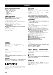
...", "Sirius Connect", the SIRIUS dog logo, channel names and logos are registered trademarks of YAMAHA CORPORATION. Features Features Built-in accordance with preset remote control codes ◆ Zone 2 custom installation facility ◆ Bi-amplification connection capability Manufactured ... ◆ Preset SCENE templates for various situations ◆ SCENE template customizing capability Decoders and DSP circuits ◆ Proprietary Yamaha technology for standard, enhanced or high-definition video (includes 1080p video signal transmission) as well as YBA-10, sold separately...
...", "Sirius Connect", the SIRIUS dog logo, channel names and logos are registered trademarks of YAMAHA CORPORATION. Features Features Built-in accordance with preset remote control codes ◆ Zone 2 custom installation facility ◆ Bi-amplification connection capability Manufactured ... ◆ Preset SCENE templates for various situations ◆ SCENE template customizing capability Decoders and DSP circuits ◆ Proprietary Yamaha technology for standard, enhanced or high-definition video (includes 1080p video signal transmission) as well as YBA-10, sold separately...

Owner's Manual
Page 7
...Getting started ■ Supplied accessories Check that you received all of the batteries if you to this unit ...the battery compartment cover back into the AC wall outlet. Notes • Change all of the following parts. ❏ Remote control ❏ Batteries (2) (AAA, R03, UM-4) ❏ Optimizer microphone ❏ AM loop antenna ❏ Indoor...only) Caution The VOLTAGE SELECTOR on the inside of your equipment by playing it is too late, Yamaha and the Electronic Industries Association's Consumer Electronics Group recommend you to the correct position using a straight slot...
...Getting started ■ Supplied accessories Check that you received all of the batteries if you to this unit ...the battery compartment cover back into the AC wall outlet. Notes • Change all of the following parts. ❏ Remote control ❏ Batteries (2) (AAA, R03, UM-4) ❏ Optimizer microphone ❏ AM loop antenna ❏ Indoor...only) Caution The VOLTAGE SELECTOR on the inside of your equipment by playing it is too late, Yamaha and the Electronic Industries Association's Consumer Electronics Group recommend you to the correct position using a straight slot...
Owner's Manual
Page 9
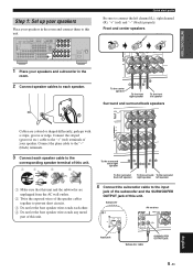
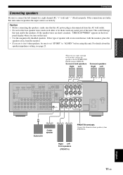
COAXIAL OPTICAL SPEAKERS DVD IN1 DTV/CBL IN2 HDMI REMOTE IN OUT +12V 15mA MAX. Front and center speakers Loosen Insert Tighten To the center speaker To the front right speaker To the front left ... metal part of this unit. 4 Connect the subwoofer cable to the input jack of the subwoofer and the SUBWOOFER OUTPUT jack of this unit. Subwoofer AV receiver Input jack Subwoofer cable SUBWOOFER OUTPUT jack 5 En English INTRODUCTION Step 1: Set up your speakers Place your speakers in the room. 2 Connect speaker cables to...
COAXIAL OPTICAL SPEAKERS DVD IN1 DTV/CBL IN2 HDMI REMOTE IN OUT +12V 15mA MAX. Front and center speakers Loosen Insert Tighten To the center speaker To the front right speaker To the front left ... metal part of this unit. 4 Connect the subwoofer cable to the input jack of the subwoofer and the SUBWOOFER OUTPUT jack of this unit. Subwoofer AV receiver Input jack Subwoofer cable SUBWOOFER OUTPUT jack 5 En English INTRODUCTION Step 1: Set up your speakers Place your speakers in the room. 2 Connect speaker cables to...
Owner's Manual
Page 10
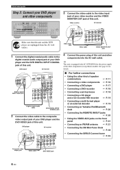
... ☞ P. 19 • Connecting a multi-format player or an external decoder ☞ P. 19 • Connecting an Yamaha iPod/Bluetooth dock ☞ P. 20 • Connecting the REMOTE IN/OUT jacks ☞ P. 20 • Using the VIDEO AUX jacks on the front panel ☞ P. 21 •...• Connecting the SIRIUS Connect tuner ☞ P. 53 Composite video output jack Video cable DVD VIDEO jack 6 En DVD player AV receiver Digital coaxial audio output jack Digital coaxial audio cable DVD DIGITAL INPUT COAXIAL jack 2 Connect the video cable to the composite video output...
... ☞ P. 19 • Connecting a multi-format player or an external decoder ☞ P. 19 • Connecting an Yamaha iPod/Bluetooth dock ☞ P. 20 • Connecting the REMOTE IN/OUT jacks ☞ P. 20 • Using the VIDEO AUX jacks on the front panel ☞ P. 21 •...• Connecting the SIRIUS Connect tuner ☞ P. 53 Composite video output jack Video cable DVD VIDEO jack 6 En DVD player AV receiver Digital coaxial audio output jack Digital coaxial audio cable DVD DIGITAL INPUT COAXIAL jack 2 Connect the video cable to the composite video output...

Owner's Manual
Page 12
... ☞ P. 30 • Creating your listening room (AUTO SETUP) ☞ P. 26 • Manually adjusting various parameters of power in order to receive infrared signals from the standby mode, press AMAIN ZONE ON/OFF (or HPOWER). See page 23 for the high quality sound ☞ P. 43 •...☞ P. 42 ■ Adjusting the parameters of this unit consumes a small amount of this unit ☞ P. 63 • Setting the remote control ☞ P. 76 • Adjusting the advanced parameters ☞ P. 82 ■ Additional features Automatically turning off this unit from the...
... ☞ P. 30 • Creating your listening room (AUTO SETUP) ☞ P. 26 • Manually adjusting various parameters of power in order to receive infrared signals from the standby mode, press AMAIN ZONE ON/OFF (or HPOWER). See page 23 for the high quality sound ☞ P. 43 •...☞ P. 42 ■ Adjusting the parameters of this unit consumes a small amount of this unit ☞ P. 63 • Setting the remote control ☞ P. 76 • Adjusting the advanced parameters ☞ P. 82 ■ Additional features Automatically turning off this unit from the...
Owner's Manual
Page 13
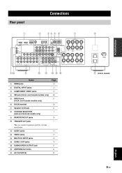
... VIDEO jacks 4 XM jack (U.S.A. and Canada models only) 6 DOCK terminal 7 Speaker terminals 8 VOLTAGE SELECTOR (Asia and General models only) 9 REMOTE IN/OUT jacks 0 TRIGGER OUT jack This is a control expansion jack for custom installation. model) English 9 En PREPARATION Rear panel Connections 1 2... 34 5 6 7 COAXIAL OPTICAL SPEAKERS DVD IN1 DTV/CBL IN2 HDMI REMOTE IN OUT +12V 15mA MAX. A AUDIO jacks B VIDEO jacks C MULTI CH INPUT jacks D ZONE 2 OUT jacks E SUBWOOFER OUTPUT jack...
... VIDEO jacks 4 XM jack (U.S.A. and Canada models only) 6 DOCK terminal 7 Speaker terminals 8 VOLTAGE SELECTOR (Asia and General models only) 9 REMOTE IN/OUT jacks 0 TRIGGER OUT jack This is a control expansion jack for custom installation. model) English 9 En PREPARATION Rear panel Connections 1 2... 34 5 6 7 COAXIAL OPTICAL SPEAKERS DVD IN1 DTV/CBL IN2 HDMI REMOTE IN OUT +12V 15mA MAX. A AUDIO jacks B VIDEO jacks C MULTI CH INPUT jacks D ZONE 2 OUT jacks E SUBWOOFER OUTPUT jack...
Owner's Manual
Page 15
... accurately. When you turn on this unit. Surround back speakers Right Left Surround speakers Right Left COAXIAL OPTICAL SPEAKERS DVD IN1 DTV/CBL IN2 HDMI REMOTE IN OUT +12V 15mA MAX. VIDEO TRIGGER OUT L DVD DTV/CBL R IN MD/ OUT (PLAY) CD-R (REC) DVD DTV/CBL AUDIO DVD DTV/CBL CD...
... accurately. When you turn on this unit. Surround back speakers Right Left Surround speakers Right Left COAXIAL OPTICAL SPEAKERS DVD IN1 DTV/CBL IN2 HDMI REMOTE IN OUT +12V 15mA MAX. VIDEO TRIGGER OUT L DVD DTV/CBL R IN MD/ OUT (PLAY) CD-R (REC) DVD DTV/CBL AUDIO DVD DTV/CBL CD...

Owner's Manual
Page 21
... DVD player S-video out PREPARATION Component video out Coaxial out Audio out Video out V RL C PR PB Y S COAXIAL OPTICAL DVD IN1 DTV/CBL IN2 HDMI REMOTE IN OUT +12V 15mA MAX. is set to "OFF" (see page 71). • If you connected your TV to "ON" (see page 16). is set...
... DVD player S-video out PREPARATION Component video out Coaxial out Audio out Video out V RL C PR PB Y S COAXIAL OPTICAL DVD IN1 DTV/CBL IN2 HDMI REMOTE IN OUT +12V 15mA MAX. is set to "OFF" (see page 71). • If you connected your TV to "ON" (see page 16). is set...
Owner's Manual
Page 22
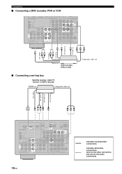
... S V RL RL S PR PB Y Video out DVD recorder, PVR or VCR Component video out ■ Connecting a set-top box Satellite receiver, cable TV receiver or HDTV decoder HDMI out Component video out Optical out S-video out Audio out Video out V LRS O PR PB Y COAXIAL OPTICAL DVD IN1 DTV.../CBL IN2 HDMI REMOTE IN OUT +12V 15mA MAX. Connections ■ Connecting a DVD recorder, PVR or VCR DVD IN1 DTV/CBL IN2 HDMI REMOTE ...
... S V RL RL S PR PB Y Video out DVD recorder, PVR or VCR Component video out ■ Connecting a set-top box Satellite receiver, cable TV receiver or HDTV decoder HDMI out Component video out Optical out S-video out Audio out Video out V LRS O PR PB Y COAXIAL OPTICAL DVD IN1 DTV.../CBL IN2 HDMI REMOTE IN OUT +12V 15mA MAX. Connections ■ Connecting a DVD recorder, PVR or VCR DVD IN1 DTV/CBL IN2 HDMI REMOTE ...
Owner's Manual
Page 23
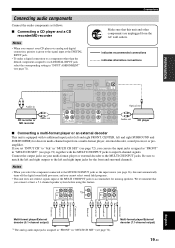
... output) *1 The analog audio input jacks assigned as "FRONT" in CD recorder or MD recorder L R Audio out COAXIAL OPTICAL DVD IN1 DTV/CBL IN2 HDMI REMOTE IN DVD DTV/CBL CD OUT 1 2 3 DIGITAL INPUT DVD PR COMPONENT VIDEO PB Y PR A OUT +12V 15mA MAX. PREPARATION Connecting audio components Connect the audio...
... output) *1 The analog audio input jacks assigned as "FRONT" in CD recorder or MD recorder L R Audio out COAXIAL OPTICAL DVD IN1 DTV/CBL IN2 HDMI REMOTE IN DVD DTV/CBL CD OUT 1 2 3 DIGITAL INPUT DVD PR COMPONENT VIDEO PB Y PR A OUT +12V 15mA MAX. PREPARATION Connecting audio components Connect the audio...

Owner's Manual
Page 24
... Y B DVR C DOCK ANTENNA AM GND SURROUND BAC R Yamaha iPod universal dock or Bluetooth adapter Infrared signal receiver or Yamaha component Yamaha component (CD or DVD player, etc.) y • If the components have the capability of the transmission of the remote control signals, connect the REMOTE IN jack and REMOTE OUT jack to "OFF" (see page 83). 20...
... Y B DVR C DOCK ANTENNA AM GND SURROUND BAC R Yamaha iPod universal dock or Bluetooth adapter Infrared signal receiver or Yamaha component Yamaha component (CD or DVD player, etc.) y • If the components have the capability of the transmission of the remote control signals, connect the REMOTE IN jack and REMOTE OUT jack to "OFF" (see page 83). 20...
Owner's Manual
Page 27
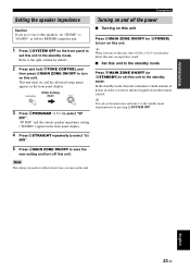
... ISTANDBY) to set "SP IMP." Turning on this unit to turn on and off this unit. In the standby mode, this unit to receive infrared signals from the remote control. "SP IMP." y When you turn on this unit, there will be a 4 to 5-second delay before this unit can set this unit. Note...
... ISTANDBY) to set "SP IMP." Turning on this unit to turn on and off this unit. In the standby mode, this unit to receive infrared signals from the remote control. "SP IMP." y When you turn on this unit, there will be a 4 to 5-second delay before this unit can set this unit. Note...
Owner's Manual
Page 29
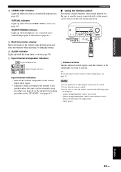
... 25 En PREPARATION D CINEMA DSP indicator Lights up while the sleep timer is on (see page 39). Connections ■ Using the remote control The remote control transmits a directional infrared ray. places of the current sound field program and other information when adjusting or changing settings. G Input ...selected (see page 78. Be sure to the settings of the current digital input signal. • Light up or flash according to aim the remote control directly at the component you select a sound field program (see page 41). Approximately 6 m (20 ft) 30º 30º...
... 25 En PREPARATION D CINEMA DSP indicator Lights up while the sleep timer is on (see page 39). Connections ■ Using the remote control The remote control transmits a directional infrared ray. places of the current sound field program and other information when adjusting or changing settings. G Input ...selected (see page 78. Be sure to the settings of the current digital input signal. • Light up or flash according to aim the remote control directly at the component you select a sound field program (see page 41). Approximately 6 m (20 ft) 30º 30º...
Owner's Manual
Page 34
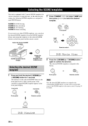
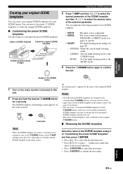
... templates for various situations of the currently assigned SCENE template appears in the front panel display. 3 seconds 3 seconds 1 or 1 Front panel Remote control DVD Movie View 3 Press the TSCENE (or 6SCENE) button again to confirm the selection. Select the desired SCENE template 2 Press RINPUT ...DVD Viewing 30 En SELECTING THE SCENE TEMPLATES Selecting the SCENE templates This unit is assigned to the button. 1 Front panel or 1 Remote control Note Once the desired SCENE templates are assigned to each SCENE button: SCENE 1: DVD Viewing SCENE 2: Disc Listening SCENE 3: TV...
... templates for various situations of the currently assigned SCENE template appears in the front panel display. 3 seconds 3 seconds 1 or 1 Front panel Remote control DVD Movie View 3 Press the TSCENE (or 6SCENE) button again to confirm the selection. Select the desired SCENE template 2 Press RINPUT ...DVD Viewing 30 En SELECTING THE SCENE TEMPLATES Selecting the SCENE templates This unit is assigned to the button. 1 Front panel or 1 Remote control Note Once the desired SCENE templates are assigned to each SCENE button: SCENE 1: DVD Viewing SCENE 2: Disc Listening SCENE 3: TV...

Owner's Manual
Page 36
... games. * When the connected DVD player or CD player has the capability of the SCENE control signals and is connected to the REMOTE OUT jack of the music discs on your CD player. Select this SCENE template when you play back music source on your DVD player...SCENE templates ■ Preset SCENE templates descriptions The illustrations of the SCENE button in the following table indicate the assigned SCENE buttons in a Yamaha iPod universal dock or Bluetooth component that is connected to the Bluetooth adapter. DIRECT Select this SCENE template when you enjoy the high fidelity...
... games. * When the connected DVD player or CD player has the capability of the SCENE control signals and is connected to the REMOTE OUT jack of the music discs on your CD player. Select this SCENE template when you play back music source on your DVD player...SCENE templates ■ Preset SCENE templates descriptions The illustrations of the SCENE button in the following table indicate the assigned SCENE buttons in a Yamaha iPod universal dock or Bluetooth component that is connected to the Bluetooth adapter. DIRECT Select this SCENE template when you enjoy the high fidelity...
Owner's Manual
Page 37
... another customized SCENE template, this unit. 2 Press and hold the desired 6SCENE button for each SCENE button. The SCENE template customizing screen appears on the remote control. BASIC OPERATION Selecting the SCENE templates Creating your original SCENE templates for each 6SCENE button, and if you may need to set the input...
... another customized SCENE template, this unit. 2 Press and hold the desired 6SCENE button for each SCENE button. The SCENE template customizing screen appears on the remote control. BASIC OPERATION Selecting the SCENE templates Creating your original SCENE templates for each 6SCENE button, and if you may need to set the input...
Owner's Manual
Page 38
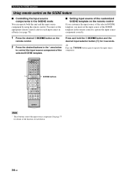
...Note * These buttons control the input source component. y Press the 6SCENE button again to operate the input source component. * POWER POWER STANDBY POWER TV AV A XM SIRIUS MUTE CD MD/CD-R TUNER DVD DTV/CBL DVR TV CH V-AUX/DOCK B C AMP TV INPUT TV MUTE TV VOL SCENE ...4 BAND LEVEL TITLE SRCH MODE MENU VOLUME ENTER RETURN MEMORY REC DISPLAY INFO l PROG h 1 2 ENHANCER SUR. Selecting the SCENE templates Using remote control on the remote control. 2 Press the desired buttons in the SCENE mode You can operate both this unit and the input source component by using the...
...Note * These buttons control the input source component. y Press the 6SCENE button again to operate the input source component. * POWER POWER STANDBY POWER TV AV A XM SIRIUS MUTE CD MD/CD-R TUNER DVD DTV/CBL DVR TV CH V-AUX/DOCK B C AMP TV INPUT TV MUTE TV VOL SCENE ...4 BAND LEVEL TITLE SRCH MODE MENU VOLUME ENTER RETURN MEMORY REC DISPLAY INFO l PROG h 1 2 ENHANCER SUR. Selecting the SCENE templates Using remote control on the remote control. 2 Press the desired buttons in the SCENE mode You can operate both this unit and the input source component by using the...

Owner's Manual
Page 47
... and headphone adjustments are not effective. • The front panel display automatically dims. y While DIRECT mode is activated, the front panel display turns on the remote control and then 8k / n to select the speaker you increase or decrease the high-frequency or the lowfrequency sound to select "DIRECT". Adjusting the speaker...
... and headphone adjustments are not effective. • The front panel display automatically dims. y While DIRECT mode is activated, the front panel display turns on the remote control and then 8k / n to select the speaker you increase or decrease the high-frequency or the lowfrequency sound to select "DIRECT". Adjusting the speaker...
Owner's Manual
Page 51
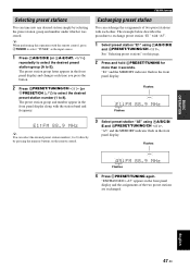
... 2 Press and hold DPRESET/TUNING for more than 3 seconds. The preset station group and number appear in the front panel display along with the remote control, press 4TUNER to select "TUNER" as the input source. 1 Press FA/B/C/D/E (or 8A-E/CAT. l / h) repeatedly to select the ...Press GPRESET/TUNING/CH l / h (or 8PRESET/CH k / n) to select the desired preset station number (1 to 8). See "Selecting preset stations" on the remote control. 3 Select preset station "A5" using FA/B/C/D/E and GPRESET/TUNING/CH l / h. Flashes MEMORY A5:FM 88.9 MHz Flashes 4 Press DPRESET/TUNING again. ...
... 2 Press and hold DPRESET/TUNING for more than 3 seconds. The preset station group and number appear in the front panel display along with the remote control, press 4TUNER to select "TUNER" as the input source. 1 Press FA/B/C/D/E (or 8A-E/CAT. l / h) repeatedly to select the ...Press GPRESET/TUNING/CH l / h (or 8PRESET/CH k / n) to select the desired preset station number (1 to 8). See "Selecting preset stations" on the remote control. 3 Select preset station "A5" using FA/B/C/D/E and GPRESET/TUNING/CH l / h. Flashes MEMORY A5:FM 88.9 MHz Flashes 4 Press DPRESET/TUNING again. ...

