
Owner's Manual
Page 8
... 31 Selecting Channels 32 Selecting Fader Modes 33 Metering 34 4 Connections and Setup 37 Connections 37 Wordclock Connections and Settings 40 Input and Output Patching 43 5 Tutorial 47 Connections and Setup 47 Initial Track Recording 49 Overdubbing to Other Tracks 60 Mixing Recorded Tracks into Stereo (Mixdown 63 6 Analog I/O & Digital I/O 69 Analog Inputs & Outputs 69 Digital Inputs & Outputs 71 Converting Sampling Rates of Signals Received at I/O Card Inputs 72 Monitoring Digital Input Channel Status 73 Dithering Digital Outputs 74 Setting the Transfer Format for Higher...
... 31 Selecting Channels 32 Selecting Fader Modes 33 Metering 34 4 Connections and Setup 37 Connections 37 Wordclock Connections and Settings 40 Input and Output Patching 43 5 Tutorial 47 Connections and Setup 47 Initial Track Recording 49 Overdubbing to Other Tracks 60 Mixing Recorded Tracks into Stereo (Mixdown 63 6 Analog I/O & Digital I/O 69 Analog Inputs & Outputs 69 Digital Inputs & Outputs 71 Converting Sampling Rates of Signals Received at I/O Card Inputs 72 Monitoring Digital Input Channel Status 73 Dithering Digital Outputs 74 Setting the Transfer Format for Higher...
Owner's Manual
Page 10
... 18 MIDI 211 MIDI & the 01V96 211 MIDI Port Setup 212 Assigning Scenes to Program Changes for Remote Recall 215 Assigning Parameters to Control Changes for Real-time Control 216 Controlling Parameters by Using Parameter Changes 221 Transmitting Parameter Settings via MIDI (Bulk Dump 222 19 Other Functions 225 Changing the Input and Output Channel Names 225 Setting Preferences 226 Creating a Custom Layer by Combining Channels (User Assignable Layer) . . . 229 Using the Oscillator 230 Using the User Defined Keys 231 Using Operation Lock 233 Cascading Consoles 234...
... 18 MIDI 211 MIDI & the 01V96 211 MIDI Port Setup 212 Assigning Scenes to Program Changes for Remote Recall 215 Assigning Parameters to Control Changes for Real-time Control 216 Controlling Parameters by Using Parameter Changes 221 Transmitting Parameter Settings via MIDI (Bulk Dump 222 19 Other Functions 225 Changing the Input and Output Channel Names 225 Setting Preferences 226 Creating a Custom Layer by Combining Channels (User Assignable Layer) . . . 229 Using the Oscillator 230 Using the User Defined Keys 231 Using Operation Lock 233 Cascading Consoles 234...

Owner's Manual
Page 11
... of channel EQ parameters. • 8 USER-DEFINED KEYS enable you for DAWs (Digital Audio Workstations) as 40-channel simultaneous mixing. acy multi-track digital recorders. • You can be routed to desired output jacks. 01V96-Owner's Manual The 01V96 offers the following features: ■ Hardware Features • 100-mm motorized faders x 17 • Faders can set levels for use with switchable +48 V phantom power and 4 line inputs • 12 analog inserts • Any Bus Outs or Channel Inserts can...
... of channel EQ parameters. • 8 USER-DEFINED KEYS enable you for DAWs (Digital Audio Workstations) as 40-channel simultaneous mixing. acy multi-track digital recorders. • You can be routed to desired output jacks. 01V96-Owner's Manual The 01V96 offers the following features: ■ Hardware Features • 100-mm motorized faders x 17 • Faders can set levels for use with switchable +48 V phantom power and 4 line inputs • 12 analog inserts • Any Bus Outs or Channel Inserts can...
Owner's Manual
Page 12
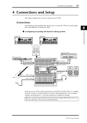
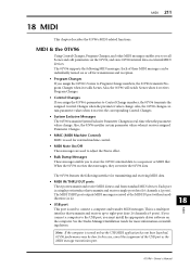
..., and other DAWs that support the Pro Tools protocol • Control an external recorder via MMC commands. ■ MIDI • Equipped with MIDI ports and a USB port for computer connection • Scene recall and mix parameter changes via MIDI 01V96-Owner's Manual 12 Chapter 1-Welcome ■ Channel Configuration • 32 Input Channels and four ST IN channels can be mixed at a time. Group multiple channels and pair channels for stereo. • Eight Bus Outs and eight Aux Sends.
..., and other DAWs that support the Pro Tools protocol • Control an external recorder via MMC commands. ■ MIDI • Equipped with MIDI ports and a USB port for computer connection • Scene recall and mix parameter changes via MIDI 01V96-Owner's Manual 12 Chapter 1-Welcome ■ Channel Configuration • 32 Input Channels and four ST IN channels can be mixed at a time. Group multiple channels and pair channels for stereo. • Eight Bus Outs and eight Aux Sends.
Owner's Manual
Page 15
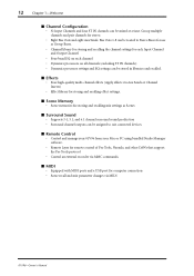
Adjust the Pad switch and GAIN control so that the indicator rarely lights up at the 2TR IN connectors are typically used to AD Input Channels 15 and 16. C MONITOR LEVEL control This control adjusts the monitoring level of stereo headphones to -40 dB when the Pad is on. 2 Control Surface & Rear Panel F PEAK indicators These indicators light up when the input signal level exceeds -34 dB. The signals output from the MONITOR OUT connectors are always the...
Adjust the Pad switch and GAIN control so that the indicator rarely lights up at the 2TR IN connectors are typically used to AD Input Channels 15 and 16. C MONITOR LEVEL control This control adjusts the monitoring level of stereo headphones to -40 dB when the Pad is on. 2 Control Surface & Rear Panel F PEAK indicators These indicators light up when the input signal level exceeds -34 dB. The signals output from the MONITOR OUT connectors are always the...
Owner's Manual
Page 37
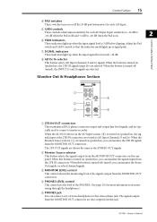
... LEVEL -16 -60 GAIN +4 GAIN -26 +4 GAIN -26 MONITOR OUT PEAK SIGNAL 13 PEAK SIGNAL 14 15 PEAK SIGNAL 16 0 10 LEVEL PHONES DISPLAY ACCESS SCENE MEMORY SCENE DIO/SETUP MIDI UTILITY / INSERT/ PAN/ PAIR/ DELAY ROUTING GROUP PATCH DYNAMICS EQ EFFECT FADER MODE VIEW AUX 1 AUX 2 AUX 3 AUX 4 AUX 5 AUX 6 AUX 7 AUX 8 HOME (METER) LAYER 1-16 17-32 MASTER REMOTE OVER 0 -3 -6 -9 -12 -15 -18 -24 -30 -36 -48 STEREO STORE SELECTED CHANNEL PAN DEC EQUALIZER Q HIGH HIGH-MID FREQUENCY LOW-MID GAIN LOW ENTER RECALL SOLO...
... LEVEL -16 -60 GAIN +4 GAIN -26 +4 GAIN -26 MONITOR OUT PEAK SIGNAL 13 PEAK SIGNAL 14 15 PEAK SIGNAL 16 0 10 LEVEL PHONES DISPLAY ACCESS SCENE MEMORY SCENE DIO/SETUP MIDI UTILITY / INSERT/ PAN/ PAIR/ DELAY ROUTING GROUP PATCH DYNAMICS EQ EFFECT FADER MODE VIEW AUX 1 AUX 2 AUX 3 AUX 4 AUX 5 AUX 6 AUX 7 AUX 8 HOME (METER) LAYER 1-16 17-32 MASTER REMOTE OVER 0 -3 -6 -9 -12 -15 -18 -24 -30 -36 -48 STEREO STORE SELECTED CHANNEL PAN DEC EQUALIZER Q HIGH HIGH-MID FREQUENCY LOW-MID GAIN LOW ENTER RECALL SOLO...
Owner's Manual
Page 62
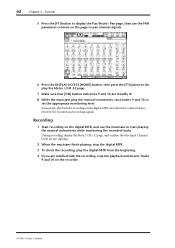
... that the Input Channel levels are satisfied with the recording, stop the playback and disarm Tracks 9 and 10 on the digital MTR, and cue the musicians to start playing the musical instruments while monitoring the recorded tracks. 62 Chapter 5-Tutorial 5 Press the [F1] button to display the Pan/Route | Pan page, then use the PAN parameter controls on the digital MTR and adjust the volume balance between the recorded and recording signals.
... that the Input Channel levels are satisfied with the recording, stop the playback and disarm Tracks 9 and 10 on the digital MTR, and cue the musicians to start playing the musical instruments while monitoring the recorded tracks. 62 Chapter 5-Tutorial 5 Press the [F1] button to display the Pan/Route | Pan page, then use the PAN parameter controls on the digital MTR and adjust the volume balance between the recorded and recording signals.
Owner's Manual
Page 90
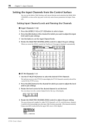
... top panel to directly control most parameters for which you want to adjust the level and/or pan settings. 3 Rotate the level control of the display.) 01V96-Owner's Manual The pan setting can be applied to adjust the pan setting. To switch between channels L and R for which you want to adjust the input level and/or pan settings. 3 Use the faders to set the level. 90 Chapter 7-Input Channels Setting the Input Channels from the Control Surface You can use the faders, [SEL] buttons...
... top panel to directly control most parameters for which you want to adjust the level and/or pan settings. 3 Rotate the level control of the display.) 01V96-Owner's Manual The pan setting can be applied to adjust the pan setting. To switch between channels L and R for which you want to adjust the input level and/or pan settings. 3 Use the faders to set the level. 90 Chapter 7-Input Channels Setting the Input Channels from the Control Surface You can use the faders, [SEL] buttons...
Owner's Manual
Page 98
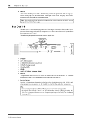
... BUS7 BUS8 STEREO L STEREO R OUTPUT PATCH • INSERT • ATT (Attenuator) • 4 BAND EQ (4-band equalizer) • COMP (Compressor) • ON (On/Off) • LEVEL • OUTPUT DELAY (Output delay) • METER The parameters and sections listed above are patched to those for stereo operation (see page 123). 01V96-Owner's Manual Bus Out 1-8 The Bus Out 1-8 section mixes signals routed from Input Channels to the specified buses, processes them using on the...
... BUS7 BUS8 STEREO L STEREO R OUTPUT PATCH • INSERT • ATT (Attenuator) • 4 BAND EQ (4-band equalizer) • COMP (Compressor) • ON (On/Off) • LEVEL • OUTPUT DELAY (Output delay) • METER The parameters and sections listed above are patched to those for stereo operation (see page 123). 01V96-Owner's Manual Bus Out 1-8 The Bus Out 1-8 section mixes signals routed from Input Channels to the specified buses, processes them using on the...
Owner's Manual
Page 155
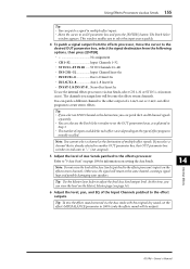
... switches its indicator to the effects processor. Tip: Use the Master layer fader to the other output of effect programs initially recalled. You can also use the internal effects processors via the Aux sends with the original dry sound, set the OUT parameter boxes, as the destination of Aux Sends patched to "-" (not assigned). 5 Adjust the level of multiple effect signals. Refer to "9 Aux Outs" on page 109 for each effect varies depending on the Meter | Master...
... switches its indicator to the effects processor. Tip: Use the Master layer fader to the other output of effect programs initially recalled. You can also use the internal effects processors via the Aux sends with the original dry sound, set the OUT parameter boxes, as the destination of Aux Sends patched to "-" (not assigned). 5 Adjust the level of multiple effect signals. Refer to "9 Aux Outs" on page 109 for each effect varies depending on the Meter | Master...
Owner's Manual
Page 161
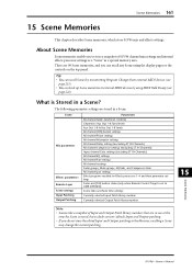
... settings Input Patching Output Patching Parameters All channel faders (and level controls) Channel to Aux Out 1-8 Send levels Aux Out 1-8 & Bus Out 1-8 levels All channel [ON] button settings All channel Phase settings All channel Attenuator settings All channel Delay settings (excluding ST IN Channels) All channel Compressor settings (excluding ST IN Channels) Input channel Gate settings (excluding ST IN Channels) All channel EQ settings All channel Pan settings All channel routings Fader groups, Mute groups, EQ links, and Compressor links All channel pair settings Effect programs recalled...
... settings Input Patching Output Patching Parameters All channel faders (and level controls) Channel to Aux Out 1-8 Send levels Aux Out 1-8 & Bus Out 1-8 levels All channel [ON] button settings All channel Phase settings All channel Attenuator settings All channel Delay settings (excluding ST IN Channels) All channel Compressor settings (excluding ST IN Channels) Input channel Gate settings (excluding ST IN Channels) All channel EQ settings All channel Pan settings All channel routings Fader groups, Mute groups, EQ links, and Compressor links All channel pair settings Effect programs recalled...
Owner's Manual
Page 162
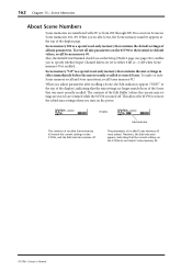
... mix parameters. This allows the 01V96 to restore the edited mix settings when you to specify whether Input Channel faders are set to their initial or default values, recall Scene memory #0. Also, the Initial Data Nominal check box on the Setup | Prefer1 page (see page 226) enables you turn on the 01V96 do not match Scene memory #2. 01V96-Owner's Manual To undo or redo Scene memory recall and store operations, recall Scene memory #U. 162 Chapter 15-Scene Memories About Scene Numbers Scene memories...
... mix parameters. This allows the 01V96 to restore the edited mix settings when you to specify whether Input Channel faders are set to their initial or default values, recall Scene memory #0. Also, the Initial Data Nominal check box on the Setup | Prefer1 page (see page 226) enables you turn on the 01V96 do not match Scene memory #2. 01V96-Owner's Manual To undo or redo Scene memory recall and store operations, recall Scene memory #U. 162 Chapter 15-Scene Memories About Scene Numbers Scene memories...
Owner's Manual
Page 211
... the 01V96's internal data to Control Change numbers, the 01V96 transmits the assigned Control Changes when the parameter values change . Each port is a multiport interface that transmits and receives single-port data (16 channels x 1 ports). See the Studio Manager Installation Guide for external machine control. • MIDI Note On/Off These messages are used to connect a computer and transfer MIDI messages. Note: If the computer is turned on the computer. Also, the 01V96 will switch Scenes...
... the 01V96's internal data to Control Change numbers, the 01V96 transmits the assigned Control Changes when the parameter values change . Each port is a multiport interface that transmits and receives single-port data (16 channels x 1 ports). See the Studio Manager Installation Guide for external machine control. • MIDI Note On/Off These messages are used to connect a computer and transfer MIDI messages. Note: If the computer is turned on the computer. Also, the 01V96 will switch Scenes...
Owner's Manual
Page 215
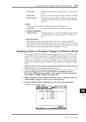
... output when you recall a Scene on the 01V96, the unit transmits the assigned Program Change to 256 steps. When the 01V96 receives a Program Change, the assigned Scene is enabled or disabled. To transfer fader value data between two cascaded 01V96s, or to record the 01V96 operation to and from a sequencer, select the HIGH button. The MIDI | Pgm Asgn page appears. 18 01V96-Owner's Manual MIDI Assigning Scenes to Program Changes for Remote Recall You can change these assignments. Assigning Scenes to Program Changes for Remote Recall...
... output when you recall a Scene on the 01V96, the unit transmits the assigned Program Change to 256 steps. When the 01V96 receives a Program Change, the assigned Scene is enabled or disabled. To transfer fader value data between two cascaded 01V96s, or to record the 01V96 operation to and from a sequencer, select the HIGH button. The MIDI | Pgm Asgn page appears. 18 01V96-Owner's Manual MIDI Assigning Scenes to Program Changes for Remote Recall You can change these assignments. Assigning Scenes to Program Changes for Remote Recall...
Owner's Manual
Page 241
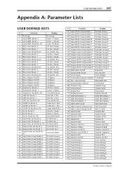
... Control Room Monitor MONO C-R MONO 66 Pan / Surround Link PAN/SURR LINK 67 Channel Name ID/Short CH ID/Short 68 Channel Copy Channel Copy 69 Channel Paste Channel Paste 70 Display Back Display Back 71 Display Forward Display Forward 72 UDEF KEYS BANK +1 UDEF KEYS BANK+1 73 UDEF KEYS BANK -1 UDEF KEYS BANK-1 74 UDEF KEYS BANK X UDEF KEYS BANK x 75 MIDI NOTE No.XX MIDI NOTE XXX 76 MIDI Program change No.XX MIDI PGM XXX 77 MIDI Control Change...
... Control Room Monitor MONO C-R MONO 66 Pan / Surround Link PAN/SURR LINK 67 Channel Name ID/Short CH ID/Short 68 Channel Copy Channel Copy 69 Channel Paste Channel Paste 70 Display Back Display Back 71 Display Forward Display Forward 72 UDEF KEYS BANK +1 UDEF KEYS BANK+1 73 UDEF KEYS BANK -1 UDEF KEYS BANK-1 74 UDEF KEYS BANK X UDEF KEYS BANK x 75 MIDI NOTE No.XX MIDI NOTE XXX 76 MIDI Program change No.XX MIDI PGM XXX 77 MIDI Control Change...
Owner's Manual
Page 324
... inputs & outputs 69 Assigne Control changes 216 MIDI messages 205 Program changes 215 Remote Layer 185 USER DEFINED KEYS 193 Attenuator 83, 99, 110 Output signals 106 Auto Channel Select preference ....... 227 Auto Direct Out On preference ....... 228 Auto EQUALIZER Display preference . 227 AUTO PAN 259 Auto PAN Display preference .......... 227 Auto SOLO Display preference ....... 227 Auto update function 165 Auto WORD CLOCK Display preference 227 AUX 1-AUX 8 buttons 17 Aux outs 109 Aux send mode 114, 118 Aux sends 113 Attenuating 110 Comp settings 111 Copying channel fader...
... inputs & outputs 69 Assigne Control changes 216 MIDI messages 205 Program changes 215 Remote Layer 185 USER DEFINED KEYS 193 Attenuator 83, 99, 110 Output signals 106 Auto Channel Select preference ....... 227 Auto Direct Out On preference ....... 228 Auto EQUALIZER Display preference . 227 AUTO PAN 259 Auto PAN Display preference .......... 227 Auto SOLO Display preference ....... 227 Auto update function 165 Auto WORD CLOCK Display preference 227 AUX 1-AUX 8 buttons 17 Aux outs 109 Aux send mode 114, 118 Aux sends 113 Attenuating 110 Comp settings 111 Copying channel fader...
Owner's Manual
Page 325
... 1-4 166 STEREO 167 FAST 141 Fast Meter Fall Time preference ...... 227 FB.GAIN 80 Features 11 Channel configuration 12 Effects 12 Hardware 11 Inputs and Outputs 11 MIDI 12 Remote control 12 Scene memory 12 Sonic specifications 11 Surround sound 12 Fixed mode 114, 118 FLANGE 258 FREQUENCY control 20 FS 73 G GAIN controls 15, 20, 70 Gain of the AD card 37 GANG 85 Gate library 179 GATE REVERB 255...
... 1-4 166 STEREO 167 FAST 141 Fast Meter Fall Time preference ...... 227 FB.GAIN 80 Features 11 Channel configuration 12 Effects 12 Hardware 11 Inputs and Outputs 11 MIDI 12 Remote control 12 Scene memory 12 Sonic specifications 11 Surround sound 12 Fixed mode 114, 118 FLANGE 258 FREQUENCY control 20 FS 73 G GAIN controls 15, 20, 70 Gain of the AD card 37 GANG 85 Gate library 179 GATE REVERB 255...
Studio Manager Installation Guide
Page 4
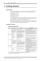
... 02R961 Yamaha CBX Driver Yamaha USB MIDI Driver (Windows 98, Me) Yamaha USB MIDI Driver (Windows 2000, XP) Card_ Card Filer1 Acroread\English SM_\DM2000 SM_\02R96 Macintosh OMS_ Acrobat Reader,1, 2 Studio Manager for DM20001 Studio Manager for 02R961 Open Music System (OMS) 2.3.81, 2 OMS Setup for YAMAHA USBdrv_ YAMAHA USB MIDI Driver Card_ Card Filer1 Adobe Acrobat Reader software for viewing the PDF manuals. Adobe Acrobat Reader software for viewing the PDF manuals. Studio Manager for Studio Manager can control your Yamaha digital mixing console from...
... 02R961 Yamaha CBX Driver Yamaha USB MIDI Driver (Windows 98, Me) Yamaha USB MIDI Driver (Windows 2000, XP) Card_ Card Filer1 Acroread\English SM_\DM2000 SM_\02R96 Macintosh OMS_ Acrobat Reader,1, 2 Studio Manager for DM20001 Studio Manager for 02R961 Open Music System (OMS) 2.3.81, 2 OMS Setup for YAMAHA USBdrv_ YAMAHA USB MIDI Driver Card_ Card Filer1 Adobe Acrobat Reader software for viewing the PDF manuals. Adobe Acrobat Reader software for viewing the PDF manuals. Studio Manager for Studio Manager can control your Yamaha digital mixing console from...
Studio Manager Installation Guide
Page 17
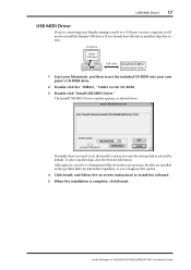
... set the Install Location, because the startup disk is complete, click Restart. To select another disk, click the Switch Disk button. Studio Manager for DM2000/DM1000/02R96/01V96-Installation Guide The Install USB MIDI Driver window appears, as shown below. USB MIDI Driver 17 USB MIDI Driver If you're connecting your Yamaha mixing console to a USB port on your computer's CD-ROM drive. 2 Double-click the "USBdrv_" folder on -screen instructions to install the software. 5 When the installation...
... set the Install Location, because the startup disk is complete, click Restart. To select another disk, click the Switch Disk button. Studio Manager for DM2000/DM1000/02R96/01V96-Installation Guide The Install USB MIDI Driver window appears, as shown below. USB MIDI Driver 17 USB MIDI Driver If you're connecting your Yamaha mixing console to a USB port on your computer's CD-ROM drive. 2 Double-click the "USBdrv_" folder on -screen instructions to install the software. 5 When the installation...
Studio Manager Installation Guide
Page 22
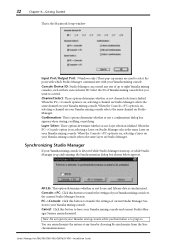
... menus are used to the current Studio Manager Session. When the PC->Console option is on, selecting a channel on Studio Manager selects the same channel on your Yamaha mixing console to select the ports with which Studio Manager communicates with its own exclusive ID. Studio Manager for DM2000/DM1000/02R96/01V96-Installation Guide 22 Chapter 4-Getting Started This is the Macintosh Setup window Input Port/Output Port: (Windows only) These...
... menus are used to the current Studio Manager Session. When the PC->Console option is on, selecting a channel on Studio Manager selects the same channel on your Yamaha mixing console to select the ports with which Studio Manager communicates with its own exclusive ID. Studio Manager for DM2000/DM1000/02R96/01V96-Installation Guide 22 Chapter 4-Getting Started This is the Macintosh Setup window Input Port/Output Port: (Windows only) These...


