
Owner's Manual
Page 7
..., these chapters have been organized in , it's recommend that appear on the display pages. Conventions Used in use . 01V96-Owner's Manual References to operate the 01V96 Digital Mixing Console. The Table of Contents can press (e.g., ENTER and DISPLAY) and buttons that you read the "Operating Basics...audio files is not in this owner's manual are enclosed in the following chapters: "Input Channels," "Bus Outs," and "Aux Outs." Copying of buttons: physical buttons that complies with the manual's organization and to familiarize yourself with the warnings and cautions listed ...
..., these chapters have been organized in , it's recommend that appear on the display pages. Conventions Used in use . 01V96-Owner's Manual References to operate the 01V96 Digital Mixing Console. The Table of Contents can press (e.g., ENTER and DISPLAY) and buttons that you read the "Operating Basics...audio files is not in this owner's manual are enclosed in the following chapters: "Input Channels," "Bus Outs," and "Aux Outs." Copying of buttons: physical buttons that complies with the manual's organization and to familiarize yourself with the warnings and cautions listed ...
Owner's Manual
Page 8
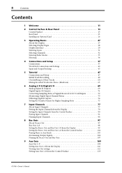
... Stereo Out and Bus Out 1-8 from the Control Surface 104 Pairing Buses or Aux Sends 105 Attenuating Output Signals 106 Naming the Stereo Out and Bus Outs 107 9 Aux Outs 109 Aux Out 1-8 109 Setting Aux Out 1-8 from the Display 110 Viewing Aux Out settings 112 Setting Aux Out 1-8 from the Control Surface 113 01V96-Owner's Manual
... Stereo Out and Bus Out 1-8 from the Control Surface 104 Pairing Buses or Aux Sends 105 Attenuating Output Signals 106 Naming the Stereo Out and Bus Outs 107 9 Aux Outs 109 Aux Out 1-8 109 Setting Aux Out 1-8 from the Display 110 Viewing Aux Out settings 112 Setting Aux Out 1-8 from the Control Surface 113 01V96-Owner's Manual
Owner's Manual
Page 9
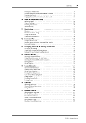
... Settings for Multiple Channels 117 Panning Aux Sends 119 Copying Channel Fader Positions to Aux Sends 120 10 Input & Output Patching 121 Input Patching 121 Output Patching 123 Patching Direct Outs ...Groups 148 Linking EQ and Compressor Parameters 150 14 Internal Effects 153 About the Internal Effects 153 Using Effects Processors via Aux Sends 154 Inserting the Internal Effects into Channels 156 Editing Effects 157 About Plug-Ins 159 15 Scene Memories 161 ... Remote Layer 202 Other DAW Remote Layers 202 MIDI Remote Layer 203 Machine Control Function 208 01V96-Owner's Manual
... Settings for Multiple Channels 117 Panning Aux Sends 119 Copying Channel Fader Positions to Aux Sends 120 10 Input & Output Patching 121 Input Patching 121 Output Patching 123 Patching Direct Outs ...Groups 148 Linking EQ and Compressor Parameters 150 14 Internal Effects 153 About the Internal Effects 153 Using Effects Processors via Aux Sends 154 Inserting the Internal Effects into Channels 156 Editing Effects 157 About Plug-Ins 159 15 Scene Memories 161 ... Remote Layer 202 Other DAW Remote Layers 202 MIDI Remote Layer 203 Machine Control Function 208 01V96-Owner's Manual

Owner's Manual
Page 11
...Aux send levels, and Bus Outs. • Four selectable software layers determine the function of channel faders. • 320 x 240 dot LCD display • Buttons and controls in the SELECTED CHANNEL section enable direct editing of channel EQ parameters. • 8 USER-DEFINED KEYS enable you for choosing the Yamaha 01V96... Digital Mixing Console. The compact 01V96 Digital Console features 24-bit/96 kHz digital audio processing without compromise, as well as popularized by ...
...Aux send levels, and Bus Outs. • Four selectable software layers determine the function of channel faders. • 320 x 240 dot LCD display • Buttons and controls in the SELECTED CHANNEL section enable direct editing of channel EQ parameters. • 8 USER-DEFINED KEYS enable you for choosing the Yamaha 01V96... Digital Mixing Console. The compact 01V96 Digital Console features 24-bit/96 kHz digital audio processing without compromise, as well as popularized by ...
Owner's Manual
Page 12
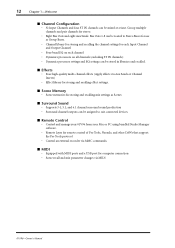
... ■ MIDI • Equipped with MIDI ports and a USB port for computer connection • Scene recall and mix parameter changes via Aux Sends or Channel Inserts) • Effect library for storing and recalling effect settings. ■ Scene Memory • Scene memories for storing and.... ■ Effects • Four high-quality multi-channel effects (Apply effects via MIDI 01V96-Owner's Manual Group multiple channels and pair channels for stereo. • Eight Bus Outs and eight Aux Sends. 12 Chapter 1-Welcome ■ Channel Configuration • 32 Input Channels ...
... ■ MIDI • Equipped with MIDI ports and a USB port for computer connection • Scene recall and mix parameter changes via Aux Sends or Channel Inserts) • Effect library for storing and recalling effect settings. ■ Scene Memory • Scene memories for storing and.... ■ Effects • Four high-quality multi-channel effects (Apply effects via MIDI 01V96-Owner's Manual Group multiple channels and pair channels for stereo. • Eight Bus Outs and eight Aux Sends. 12 Chapter 1-Welcome ■ Channel Configuration • 32 Input Channels ...
Owner's Manual
Page 13
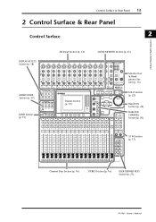
... FADER MODE Section (p. 17) LAYER Section (p. 19) SCENE DIO/SETUP MIDI UTILITY / INSERT/ PAN/ PAIR/ DELAY ROUTING GROUP PATCH DYNAMICS EQ EFFECT FADER MODE VIEW AUX 1 AUX 2 AUX 3 AUX 4 AUX 5 AUX 6 AUX 7 AUX 8 HOME (METER) LAYER 1-16 17-32 MASTER REMOTE Display Section (p. 19) OVER 0 -3 -6 -9 -12 -15 -18 -24 -30 -36 -48 STEREO STORE SELECTED CHANNEL PAN DEC... (p. 22) Data Entry Section (p. 22) SELECTED CHANNEL Section (p. 20) ST IN Section (p. 17) Channel Strip Section (p. 16) STEREO Section (p. 16) USER DEFINED KEYS Section (p. 21) 01V96-Owner's Manual
... FADER MODE Section (p. 17) LAYER Section (p. 19) SCENE DIO/SETUP MIDI UTILITY / INSERT/ PAN/ PAIR/ DELAY ROUTING GROUP PATCH DYNAMICS EQ EFFECT FADER MODE VIEW AUX 1 AUX 2 AUX 3 AUX 4 AUX 5 AUX 6 AUX 7 AUX 8 HOME (METER) LAYER 1-16 17-32 MASTER REMOTE Display Section (p. 19) OVER 0 -3 -6 -9 -12 -15 -18 -24 -30 -36 -48 STEREO STORE SELECTED CHANNEL PAN DEC... (p. 22) Data Entry Section (p. 22) SELECTED CHANNEL Section (p. 20) ST IN Section (p. 17) Channel Strip Section (p. 16) STEREO Section (p. 16) USER DEFINED KEYS Section (p. 21) 01V96-Owner's Manual
Owner's Manual
Page 16
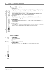
The [SOLO] button indicator of the Stereo Out. 0 5 10 15 20 30 40 50 60 70 3 STEREO 01V96-Owner's Manual B [ON] button Turns the Stereo Out on the button selected in the LAYER section (see page 17), these faders 15 30 adjust the ...selected channel input levels or the Bus Out or Aux Out levels. 20 40 4 30 50 40 60 70 50 1 17 AUX 1 STEREO Section 1 SEL 2 ON A [SEL] button Selects the Stereo Out. The [SEL] button indicator for On 0 10 channels light...
The [SOLO] button indicator of the Stereo Out. 0 5 10 15 20 30 40 50 60 70 3 STEREO 01V96-Owner's Manual B [ON] button Turns the Stereo Out on the button selected in the LAYER section (see page 17), these faders 15 30 adjust the ...selected channel input levels or the Bus Out or Aux Out levels. 20 40 4 30 50 40 60 70 50 1 17 AUX 1 STEREO Section 1 SEL 2 ON A [SEL] button Selects the Stereo Out. The [SEL] button indicator for On 0 10 channels light...

Owner's Manual
Page 17
...AUX 1 AUX 2 AUX 3 AUX 4 AUX 5 AUX 6 AUX 7 AUX 8 HOME (METER) A [AUX 1]-[AUX 8] buttons These buttons enable you to select the Aux Send you wish to control. C [SOLO] buttons These buttons solo the selected ST IN channels. D [ON] buttons These buttons turn the ST IN channels on or off. Pressing one of these buttons switches the Fader mode (see page 34). 01V96...recalls Meter pages that display Input Channel levels or Output Channel (Bus Out, Aux Out, Stereo Out) levels (see page 33), and displays the corresponding Aux page. (The selected button's indicator lights up.) You can control using ...
...AUX 1 AUX 2 AUX 3 AUX 4 AUX 5 AUX 6 AUX 7 AUX 8 HOME (METER) A [AUX 1]-[AUX 8] buttons These buttons enable you to select the Aux Send you wish to control. C [SOLO] buttons These buttons solo the selected ST IN channels. D [ON] buttons These buttons turn the ST IN channels on or off. Pressing one of these buttons switches the Fader mode (see page 34). 01V96...recalls Meter pages that display Input Channel levels or Output Channel (Bus Out, Aux Out, Stereo Out) levels (see page 33), and displays the corresponding Aux page. (The selected button's indicator lights up.) You can control using ...
Owner's Manual
Page 19
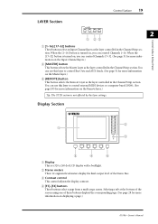
... This button selects the Remote Layer as the layer controlled in the Channel Strip section. You can use this layer to control Bus Outs and AUX Sends. (See page 31 for more information on the Remote layer.) Tip: The ST IN section is turned on displaying a page....) 01V96-Owner's Manual When the [1-16] button is a 320 x 240 dot LCD display with a backlight. Display Section 1 OVER 0 -3 -6 -9 -12 -15 -18 -24 -30 -36 -48 STEREO 2 3 5 4 6 A ...
... This button selects the Remote Layer as the layer controlled in the Channel Strip section. You can use this layer to control Bus Outs and AUX Sends. (See page 31 for more information on the Remote layer.) Tip: The ST IN section is turned on displaying a page....) 01V96-Owner's Manual When the [1-16] button is a 320 x 240 dot LCD display with a backlight. Display Section 1 OVER 0 -3 -6 -9 -12 -15 -18 -24 -30 -36 -48 STEREO 2 3 5 4 6 A ...
Owner's Manual
Page 31
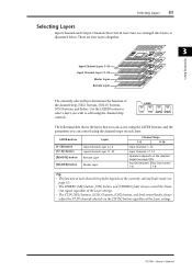
...layers that you can control using the channel strip controls. Selecting Layers 31 Selecting Layers Input Channels and Output Channels (Bus Outs & Aux Outs) are four layers altogether. 3 Operating Basics Input Channel Layer 1-16 Input Channel Layer 17-32 Master Layer Remote Layer The...level control knobs always adjust the ST IN channels selected via the [ST IN] button regardless of the Layer settings. 01V96-Owner's Manual There are arranged into layers, as illustrated below. Aux Send masters Bus Out masters 1-8 1-8 Tip: • The function of the channel strip, [SEL] buttons, [...
...layers that you can control using the channel strip controls. Selecting Layers 31 Selecting Layers Input Channels and Output Channels (Bus Outs & Aux Outs) are four layers altogether. 3 Operating Basics Input Channel Layer 1-16 Input Channel Layer 17-32 Master Layer Remote Layer The...level control knobs always adjust the ST IN channels selected via the [ST IN] button regardless of the Layer settings. 01V96-Owner's Manual There are arranged into layers, as illustrated below. Aux Send masters Bus Out masters 1-8 1-8 Tip: • The function of the channel strip, [SEL] buttons, [...
Owner's Manual
Page 33
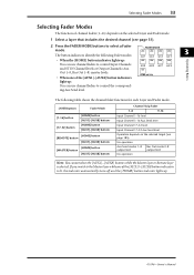
...depends on the selected Layer and Fader mode. 1 Select a layer that includes the desired channel (see page 185). The following Fader modes: AUX 1 AUX 2 AUX 3 AUX 4 3 Operating Basics • When the [HOME] button indicator lights up: You can use channel faders to the Master layer while one... of the [AUX1]-[AUX8] button indicators HOME (METER) light up . 01V96-Owner's Manual No operation Aux Send master 1-8 output level Bus Out master1-8 output level No operation Note: You cannot select the [AUX1]-[AUX8] buttons ...
...depends on the selected Layer and Fader mode. 1 Select a layer that includes the desired channel (see page 185). The following Fader modes: AUX 1 AUX 2 AUX 3 AUX 4 3 Operating Basics • When the [HOME] button indicator lights up: You can use channel faders to the Master layer while one... of the [AUX1]-[AUX8] button indicators HOME (METER) light up . 01V96-Owner's Manual No operation Aux Send master 1-8 output level Bus Out master1-8 output level No operation Note: You cannot select the [AUX1]-[AUX8] buttons ...
Owner's Manual
Page 34
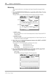
...three positions in the INPUT or OUTPUT section, then press [ENTER]. CH1-32 page This page displays the Input Channel 1-32 levels respectively. 01V96-Owner's Manual 34 Chapter 3-Operating Basics Metering This section describes how to check Input and Output Channel levels using the Meter pages. 1 ... repeatedly until the Meter | Position page appears. B OUTPUT section This section enables you to select the metering position for Output Channel (Aux Out 1-8, Bus Out 1-8, Stereo Out) signals. 2 Move the cursor to select the metering position for Input Channel and ST IN Channel signals.
...three positions in the INPUT or OUTPUT section, then press [ENTER]. CH1-32 page This page displays the Input Channel 1-32 levels respectively. 01V96-Owner's Manual 34 Chapter 3-Operating Basics Metering This section describes how to check Input and Output Channel levels using the Meter pages. 1 ... repeatedly until the Meter | Position page appears. B OUTPUT section This section enables you to select the metering position for Output Channel (Aux Out 1-8, Bus Out 1-8, Stereo Out) signals. 2 Move the cursor to select the metering position for Input Channel and ST IN Channel signals.

Owner's Manual
Page 35
Effect page This page displays the internal effects processor 1-4 input and output levels altogether. 01V96-Owner's Manual Master page This section displays the Output Channel (Aux Out 1-8, Bus Out 1-8, Stereo Out) levels altogether. - Metering 35 - ST IN page This page displays the left and right ST IN Channel 1-4 levels separately. 3 Operating Basics -
Effect page This page displays the internal effects processor 1-4 input and output levels altogether. 01V96-Owner's Manual Master page This section displays the Output Channel (Aux Out 1-8, Bus Out 1-8, Stereo Out) levels altogether. - Metering 35 - ST IN page This page displays the left and right ST IN Channel 1-4 levels separately. 3 Operating Basics -
Owner's Manual
Page 37
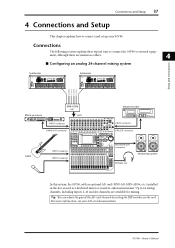
... 10 LEVEL PHONES DISPLAY ACCESS SCENE MEMORY SCENE DIO/SETUP MIDI UTILITY / INSERT/ PAN/ PAIR/ DELAY ROUTING GROUP PATCH DYNAMICS EQ EFFECT FADER MODE VIEW AUX 1 AUX 2 AUX 3 AUX 4 AUX 5 AUX 6 AUX 7 AUX 8 HOME (METER) LAYER 1-16 17-32 MASTER REMOTE OVER 0 -3 -6 -9 -12 -15 -18 -24 -30 -36 -48 STEREO STORE ... AUX 2 3 19 AUX 3 4 20 AUX 4 5 21 AUX 5 6 22 AUX 6 7 23 AUX 7 8 24 AUX 8 9 25 BUS 1 10 26 BUS 2 11 27 BUS 3 12 28 BUS 4 13 29 BUS 5 14 30 BUS 6 15 31 BUS 7 16 32 BUS 8 STEREO VOL VOL Monitoring system In this system, the 01V96, with an optional AD card (...
... 10 LEVEL PHONES DISPLAY ACCESS SCENE MEMORY SCENE DIO/SETUP MIDI UTILITY / INSERT/ PAN/ PAIR/ DELAY ROUTING GROUP PATCH DYNAMICS EQ EFFECT FADER MODE VIEW AUX 1 AUX 2 AUX 3 AUX 4 AUX 5 AUX 6 AUX 7 AUX 8 HOME (METER) LAYER 1-16 17-32 MASTER REMOTE OVER 0 -3 -6 -9 -12 -15 -18 -24 -30 -36 -48 STEREO STORE ... AUX 2 3 19 AUX 3 4 20 AUX 4 5 21 AUX 5 6 22 AUX 6 7 23 AUX 7 8 24 AUX 8 9 25 BUS 1 10 26 BUS 2 11 27 BUS 3 12 28 BUS 4 13 29 BUS 5 14 30 BUS 6 15 31 BUS 7 16 32 BUS 8 STEREO VOL VOL Monitoring system In this system, the 01V96, with an optional AD card (...
Owner's Manual
Page 38
... Control Surface Modular Synthesis Plug-in System SCENE DIO/SETUP MIDI UTILITY / INSERT/ PAN/ PAIR/ DELAY ROUTING GROUP PATCH DYNAMICS EQ EFFECT FADER MODE VIEW AUX 1 AUX 2 AUX 3 AUX 4 AUX 5 AUX 6 AUX 7 AUX 8 HOME (METER) LAYER 1-16 17-32 MASTER REMOTE OVER 0 -3 -6 -9 -12 -15 -18 -24 -30 -36 -48 STEREO STORE... AUX 2 3 19 AUX 3 4 20 AUX 4 5 21 AUX 5 6 22 AUX 6 7 23 AUX 7 8 24 AUX 8 9 25 BUS 1 10 26 BUS 2 11 27 BUS 3 12 28 BUS 4 13 29 BUS 5 14 30 BUS 6 15 31 BUS 7 16 32 BUS 8 STEREO PHONES jack VOL VOL Monitoring system In this system, the 01V96 is one ...
... Control Surface Modular Synthesis Plug-in System SCENE DIO/SETUP MIDI UTILITY / INSERT/ PAN/ PAIR/ DELAY ROUTING GROUP PATCH DYNAMICS EQ EFFECT FADER MODE VIEW AUX 1 AUX 2 AUX 3 AUX 4 AUX 5 AUX 6 AUX 7 AUX 8 HOME (METER) LAYER 1-16 17-32 MASTER REMOTE OVER 0 -3 -6 -9 -12 -15 -18 -24 -30 -36 -48 STEREO STORE... AUX 2 3 19 AUX 3 4 20 AUX 4 5 21 AUX 5 6 22 AUX 6 7 23 AUX 7 8 24 AUX 8 9 25 BUS 1 10 26 BUS 2 11 27 BUS 3 12 28 BUS 4 13 29 BUS 5 14 30 BUS 6 15 31 BUS 7 16 32 BUS 8 STEREO PHONES jack VOL VOL Monitoring system In this system, the 01V96 is one ...
Owner's Manual
Page 39
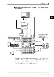
...Control Surface Modular Synthesis Plug-in System SCENE DIO/SETUP MIDI UTILITY / INSERT/ PAN/ PAIR/ DELAY ROUTING GROUP PATCH DYNAMICS EQ EFFECT FADER MODE VIEW AUX 1 AUX 2 AUX 3 AUX 4 AUX 5 AUX 6 AUX 7 AUX 8 HOME (METER) LAYER 1-16 17-32 MASTER REMOTE OVER 0 -3 -6 -9 -12 -15 -18 -24 -30 -36 -48 STEREO ... AUX 2 3 19 AUX 3 4 20 AUX 4 5 21 AUX 5 6 22 AUX 6 7 23 AUX 7 8 24 AUX 8 9 25 BUS 1 10 26 BUS 2 11 27 BUS 3 12 28 BUS 4 13 29 BUS 5 14 30 BUS 6 15 31 BUS 7 16 32 BUS 8 STEREO PHONES jack VOL VOL Monitoring system In this system, the 01V96, with an optional I/O...
...Control Surface Modular Synthesis Plug-in System SCENE DIO/SETUP MIDI UTILITY / INSERT/ PAN/ PAIR/ DELAY ROUTING GROUP PATCH DYNAMICS EQ EFFECT FADER MODE VIEW AUX 1 AUX 2 AUX 3 AUX 4 AUX 5 AUX 6 AUX 7 AUX 8 HOME (METER) LAYER 1-16 17-32 MASTER REMOTE OVER 0 -3 -6 -9 -12 -15 -18 -24 -30 -36 -48 STEREO ... AUX 2 3 19 AUX 3 4 20 AUX 4 5 21 AUX 5 6 22 AUX 6 7 23 AUX 7 8 24 AUX 8 9 25 BUS 1 10 26 BUS 2 11 27 BUS 3 12 28 BUS 4 13 29 BUS 5 14 30 BUS 6 15 31 BUS 7 16 32 BUS 8 STEREO PHONES jack VOL VOL Monitoring system In this system, the 01V96, with an optional I/O...
Owner's Manual
Page 41
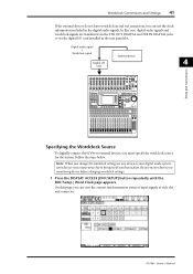
... 0 LEVEL10 PHONES DISPLAY ACCESS SCENE MEMORY SCENE DIO/SETUP MIDI UTILITY / INSERT/ PAN/ PAIR/ DELAY ROUTING GROUP PATCH DYNAMICS EQ EFFECT FADER MODE VIEW AUX 1 AUX 2 AUX 3 AUX 4 AUX 5 AUX 6 AUX 7 AUX 8 HOME (METER) LAYER 1-16 17-32 MASTER REMOTE OVER 0 -3 -6 -9 -12 -15 -18 -24 -30 -36 -48 STEREO STORE... AUX 2 3 19 AUX 3 4 20 AUX 4 5 21 AUX 5 6 22 AUX 6 7 23 AUX 7 8 24 AUX 8 9 25 BUS 1 10 26 BUS 2 11 27 BUS 3 12 28 BUS 4 13 29 BUS 5 14 30 BUS 6 15 31 BUS 7 16 32 BUS 8 STEREO Specifying the Wordclock Source To digitally connect the 01V96 to external devices, ...
... 0 LEVEL10 PHONES DISPLAY ACCESS SCENE MEMORY SCENE DIO/SETUP MIDI UTILITY / INSERT/ PAN/ PAIR/ DELAY ROUTING GROUP PATCH DYNAMICS EQ EFFECT FADER MODE VIEW AUX 1 AUX 2 AUX 3 AUX 4 AUX 5 AUX 6 AUX 7 AUX 8 HOME (METER) LAYER 1-16 17-32 MASTER REMOTE OVER 0 -3 -6 -9 -12 -15 -18 -24 -30 -36 -48 STEREO STORE... AUX 2 3 19 AUX 3 4 20 AUX 4 5 21 AUX 5 6 22 AUX 6 7 23 AUX 7 8 24 AUX 8 9 25 BUS 1 10 26 BUS 2 11 27 BUS 3 12 28 BUS 4 13 29 BUS 5 14 30 BUS 6 15 31 BUS 7 16 32 BUS 8 STEREO Specifying the Wordclock Source To digitally connect the 01V96 to external devices, ...
Owner's Manual
Page 44
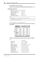
...; CAS BUS1-BUS8 Bus Out 1-8 Cascade Outs • CAS AUX1-AUX8 Aux Out 1-8 Cascade Outs • CAS ST-L/ST-R Stereo Out Cascade Outs • CASSOLOL/CASSOLOR Solo Channel Cascade Outs 01V96-Owner's Manual The parameter indicators are explained below to the output connectors are ...patching, recall Input Patch memory #00 (see page 174). Patching Omni Outs By default, the output connectors are patched as follows: • OMNI OUT connectors 1-4 Aux Out 1-4 • ADAT OUT channels 1-8 Bus Out 1-8 • Slot channels 1-8 Bus Out 1-8 • Slot channels 9-16 Bus Out 1-8 • 2TR...
...; CAS BUS1-BUS8 Bus Out 1-8 Cascade Outs • CAS AUX1-AUX8 Aux Out 1-8 Cascade Outs • CAS ST-L/ST-R Stereo Out Cascade Outs • CASSOLOL/CASSOLOR Solo Channel Cascade Outs 01V96-Owner's Manual The parameter indicators are explained below to the output connectors are ...patching, recall Input Patch memory #00 (see page 174). Patching Omni Outs By default, the output connectors are patched as follows: • OMNI OUT connectors 1-4 Aux Out 1-4 • ADAT OUT channels 1-8 Bus Out 1-8 • Slot channels 1-8 Bus Out 1-8 • Slot channels 9-16 Bus Out 1-8 • 2TR...
Owner's Manual
Page 47
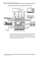
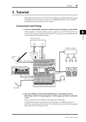
...0 LEVEL10 PHONES DISPLAY ACCESS SCENE MEMORY SCENE DIO/SETUP MIDI UTILITY / INSERT/ PAN/ PAIR/ DELAY ROUTING GROUP PATCH DYNAMICS EQ EFFECT FADER MODE VIEW AUX 1 AUX 2 AUX 3 AUX 4 AUX 5 AUX 6 AUX 7 AUX 8 HOME (METER) LAYER 1-16 17-32 MASTER REMOTE OVER 0 -3 -6 -9 -12 -15 -18 -24 -30 -36 -48 STEREO STORE... 16-track hard disk recorder is used as the wordclock master. Tutorial 47 5 Tutorial This chapter describes how to use the 01V96 for connection details.) Hard disk recorder Tutorial Track 9-16 OUT IN Track 1-8 OUT IN Headphone amplifier ADAT IN connector...
...0 LEVEL10 PHONES DISPLAY ACCESS SCENE MEMORY SCENE DIO/SETUP MIDI UTILITY / INSERT/ PAN/ PAIR/ DELAY ROUTING GROUP PATCH DYNAMICS EQ EFFECT FADER MODE VIEW AUX 1 AUX 2 AUX 3 AUX 4 AUX 5 AUX 6 AUX 7 AUX 8 HOME (METER) LAYER 1-16 17-32 MASTER REMOTE OVER 0 -3 -6 -9 -12 -15 -18 -24 -30 -36 -48 STEREO STORE... 16-track hard disk recorder is used as the wordclock master. Tutorial 47 5 Tutorial This chapter describes how to use the 01V96 for connection details.) Hard disk recorder Tutorial Track 9-16 OUT IN Track 1-8 OUT IN Headphone amplifier ADAT IN connector...
Owner's Manual
Page 63
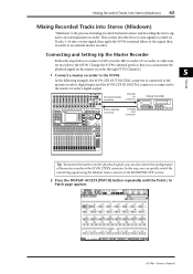
... master recorder's digital output. This section describes how to mix signals recorded on the master recorder through ST IN Channel 2. 1 Connect a master recorder to the 01V96. CH1-4 CH5-8 CH9-12 1 2 3 4 5 6 7 8 9 10 11 12 13 15 PHANTOM +48V A A A A A A A A A A A A 14 B B B B B B B B B B B B... MEMORY SCENE DIO/SETUP MIDI UTILITY / INSERT/ PAN/ PAIR/ DELAY ROUTING GROUP PATCH DYNAMICS EQ EFFECT FADER MODE VIEW AUX 1 AUX 2 AUX 3 AUX 4 AUX 5 AUX 6 AUX 7 AUX 8 HOME (METER) LAYER 1-16 17-32 MASTER REMOTE OVER 0 -3 -6 -9 -12 -15 -18 -24 ...
... master recorder's digital output. This section describes how to mix signals recorded on the master recorder through ST IN Channel 2. 1 Connect a master recorder to the 01V96. CH1-4 CH5-8 CH9-12 1 2 3 4 5 6 7 8 9 10 11 12 13 15 PHANTOM +48V A A A A A A A A A A A A 14 B B B B B B B B B B B B... MEMORY SCENE DIO/SETUP MIDI UTILITY / INSERT/ PAN/ PAIR/ DELAY ROUTING GROUP PATCH DYNAMICS EQ EFFECT FADER MODE VIEW AUX 1 AUX 2 AUX 3 AUX 4 AUX 5 AUX 6 AUX 7 AUX 8 HOME (METER) LAYER 1-16 17-32 MASTER REMOTE OVER 0 -3 -6 -9 -12 -15 -18 -24 ...
