
Owner's Manual
Page 2
...these corrective measures do not produce satisfactory results, please contact the local retailer authorized to products distributed by using one of de volgende Yamaha Service Afdeiing: Yamaha Music Nederland Service Afdeiing Kanaalweg 18-G, 3526 KL UTRECHT Tel. 030-2828425 ● Gooi de batterij ...which is coloured BROWN must be connected to accessories and/or another product use of other electronic devices. If this product or the device that your plug, proceed as follows: Yamaha Music Nederland Service Center Address: Kanaalweg 18-G, 3526 KL UTRECHT Tel: 030...
...these corrective measures do not produce satisfactory results, please contact the local retailer authorized to products distributed by using one of de volgende Yamaha Service Afdeiing: Yamaha Music Nederland Service Afdeiing Kanaalweg 18-G, 3526 KL UTRECHT Tel. 030-2828425 ● Gooi de batterij ...which is coloured BROWN must be connected to accessories and/or another product use of other electronic devices. If this product or the device that your plug, proceed as follows: Yamaha Music Nederland Service Center Address: Kanaalweg 18-G, 3526 KL UTRECHT Tel: 030...
Owner's Manual
Page 3
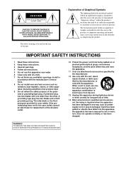
... or plug is located on or pinched particularly at plugs, convenience receptacles, and the point where they exit from the apparatus. 11 Only use this apparatus during lightning storms or when unused for long periods of the polarized or grounding-type plug. IMPORTANT SAFETY INSTRUCTIONS 1 Read these ... that produce heat. 9 Do not defeat the safety purpose of time. 14 Refer all instructions. 5 Do not use attachments/accessories specified by the manufacturer. 12 Use only with the cart, stand, tripod, bracket, or table specified by the manufacturer, or sold with arrowhead...
... or plug is located on or pinched particularly at plugs, convenience receptacles, and the point where they exit from the apparatus. 11 Only use this apparatus during lightning storms or when unused for long periods of the polarized or grounding-type plug. IMPORTANT SAFETY INSTRUCTIONS 1 Read these ... that produce heat. 9 Do not defeat the safety purpose of time. 14 Refer all instructions. 5 Do not use attachments/accessories specified by the manufacturer. 12 Use only with the cart, stand, tripod, bracket, or table specified by the manufacturer, or sold with arrowhead...
Owner's Manual
Page 4
...Important Information Warnings • Connect this unit's power cord only to an AC outlet of lightning, do so is a potential electrical shock hazard. 01V96-Owner's Manual Doing so is a fire and electrical shock hazard. • If lightning begins to occur, turn off the power switch ...hazard. • Do not touch the power plug with liquid or small metal objects on a power cord covered by Yamaha may be an electrical shock hazard. • Use only the included power cord for installing mini-YGDAI cards. Before installing any abnormality, such as inside this unit away...
...Important Information Warnings • Connect this unit's power cord only to an AC outlet of lightning, do so is a potential electrical shock hazard. 01V96-Owner's Manual Doing so is a fire and electrical shock hazard. • If lightning begins to occur, turn off the power switch ...hazard. • Do not touch the power plug with liquid or small metal objects on a power cord covered by Yamaha may be an electrical shock hazard. • Use only the included power cord for installing mini-YGDAI cards. Before installing any abnormality, such as inside this unit away...
Owner's Manual
Page 5
... follows: pin 1-ground, pin 2-hot (+), and pin 3-cold (-). • Insert TRS phone jacks are a fire hazard. Using a mobile telephone near this unit. 01V96-Owner's Manual Operating Notes v • This unit has ventilation holes along the top, front, rear, and sides to prevent the internal... temperature from the unit. • If the message "WARNING Low Battery!" If noise occurs, use or operation of time,...
... follows: pin 1-ground, pin 2-hot (+), and pin 3-cold (-). • Insert TRS phone jacks are a fire hazard. Using a mobile telephone near this unit. 01V96-Owner's Manual Operating Notes v • This unit has ventilation holes along the top, front, rear, and sides to prevent the internal... temperature from the unit. • If the message "WARNING Low Battery!" If noise occurs, use or operation of time,...
Owner's Manual
Page 7
...in this manual discusses a specific section or function of the 01V96. Conventions Used in this Manual The 01V96 features two types of signal flow, from those on the display pages. You can select pages. Installing the 01V96 This unit should be placed on a strong and stable surface, ..., "press the [ENTER] button." The Table of the commercially available music sequence data and/or digital audio files is not in use . 01V96-Owner's Manual The index can help you to familiarize yourself with the warnings and cautions listed in which you read the "Operating Basics" chapter...
...in this manual discusses a specific section or function of the 01V96. Conventions Used in this Manual The 01V96 features two types of signal flow, from those on the display pages. You can select pages. Installing the 01V96 This unit should be placed on a strong and stable surface, ..., "press the [ENTER] button." The Table of the commercially available music sequence data and/or digital audio files is not in use . 01V96-Owner's Manual The index can help you to familiarize yourself with the warnings and cautions listed in which you read the "Operating Basics" chapter...
Owner's Manual
Page 9
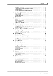
... 131 Monitor and Solo Setup 132 Using the Monitor 133 Using the Solo Function 134 12 Surround Pan 135 Using Surround Pan 135 Setting Up and ...Selecting Surround Pan Modes 136 Surround Panning 141 13 Grouping Channels & Linking Parameters 147 Grouping & Linking 147 Using...14 Internal Effects 153 About the Internal Effects 153 Using Effects Processors via Aux Sends 154 Inserting the Internal ...169 16 Libraries 171 About the Libraries 171 General Library Operation 171 Using Libraries 173 17 Remote Control 185 About Remote Function 185 Pro ...
... 131 Monitor and Solo Setup 132 Using the Monitor 133 Using the Solo Function 134 12 Surround Pan 135 Using Surround Pan 135 Setting Up and ...Selecting Surround Pan Modes 136 Surround Panning 141 13 Grouping Channels & Linking Parameters 147 Grouping & Linking 147 Using...14 Internal Effects 153 About the Internal Effects 153 Using Effects Processors via Aux Sends 154 Inserting the Internal ...169 16 Libraries 171 About the Libraries 171 General Library Operation 171 Using Libraries 173 17 Remote Control 185 About Remote Function 185 Pro ...
Owner's Manual
Page 10
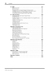
10 Contents 18 MIDI 211 MIDI & the 01V96 211 MIDI Port Setup 212 Assigning Scenes to Program Changes for Remote Recall 215 Assigning Parameters to Control Changes for Real-time Control 216 Controlling Parameters by Using Parameter Changes 221 Transmitting Parameter Settings via MIDI... by Combining Channels (User Assignable Layer) . . . 229 Using the Oscillator 230 Using the User Defined Keys 231 Using Operation Lock 233 Cascading Consoles 234 Checking the Battery and the System Version 238 Initializing the 01V96 239 Calibrating the Faders 240 Appendix A: Parameter Lists 241 USER ...
10 Contents 18 MIDI 211 MIDI & the 01V96 211 MIDI Port Setup 212 Assigning Scenes to Program Changes for Remote Recall 215 Assigning Parameters to Control Changes for Real-time Control 216 Controlling Parameters by Using Parameter Changes 221 Transmitting Parameter Settings via MIDI... by Combining Channels (User Assignable Layer) . . . 229 Using the Oscillator 230 Using the User Defined Keys 231 Using Operation Lock 233 Cascading Consoles 234 Checking the Battery and the System Version 238 Initializing the 01V96 239 Calibrating the Faders 240 Appendix A: Parameter Lists 241 USER ...

Owner's Manual
Page 11
... be routed to four Omni Outs. • Individual outputs for Stereo Out and Monitor Out • Analog 2TR In and Out for use with Tape In and Out signals • An optional card installed in the digital domain. • Input patches enable assignment of input ...Mixing Consoles. Welcome 11 1 Welcome 1 Welcome Thank you to assign functions to control 01V96 internal parameters. • ADAT optical connectors • Expansion slot for choosing the Yamaha 01V96 Digital Mixing Console. The 01V96 covers a broad range of Bus Out signals and Input Channel Direct Outs to desired output...
... be routed to four Omni Outs. • Individual outputs for Stereo Out and Monitor Out • Analog 2TR In and Out for use with Tape In and Out signals • An optional card installed in the digital domain. • Input patches enable assignment of input ...Mixing Consoles. Welcome 11 1 Welcome 1 Welcome Thank you to assign functions to control 01V96 internal parameters. • ADAT optical connectors • Expansion slot for choosing the Yamaha 01V96 Digital Mixing Console. The 01V96 covers a broad range of Bus Out signals and Input Channel Direct Outs to desired output...
Owner's Manual
Page 12
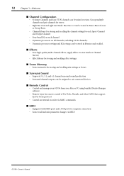
... • Surround channel outputs can be assigned to suit connected devices. ■ Remote Control • Control and manage your 01V96 from your Mac or PC using bundled Studio Manager software. • Remote Layer for remote control of Pro Tools, Nuendo, and other DAWs that support the ...Pro Tools protocol • Control an external recorder via MIDI 01V96-Owner's Manual Group multiple channels and pair channels for computer connection ...
... • Surround channel outputs can be assigned to suit connected devices. ■ Remote Control • Control and manage your 01V96 from your Mac or PC using bundled Studio Manager software. • Remote Layer for remote control of Pro Tools, Nuendo, and other DAWs that support the ...Pro Tools protocol • Control an external recorder via MIDI 01V96-Owner's Manual Group multiple channels and pair channels for computer connection ...
Owner's Manual
Page 14
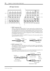
...signal from INPUT B is not supplied to INSERT jack To processor's input 1/4" phone plug Sleeve (ground) Tip (return) Sleeve (ground) From processor's output 01V96-Owner's Manual C INSERT I /O CH15/16 2TR IN 20dB 20dB 20dB 20dB +4 GAIN -26 +4 GAIN -26 -16 -60 GAIN PEAK SIGNAL -...14 15 PEAK SIGNAL 16 2 8 A INPUT connectors A/B INPUT A connectors are balanced XLR-3-31-type connectors that accept line-level and microphone signals. Use a split cable to insert an external effects processor to AD input channels. 1/4" phone plug Tip (send) Tip (send) Ring (return) 1/4" phone...
...signal from INPUT B is not supplied to INSERT jack To processor's input 1/4" phone plug Sleeve (ground) Tip (return) Sleeve (ground) From processor's output 01V96-Owner's Manual C INSERT I /O CH15/16 2TR IN 20dB 20dB 20dB 20dB +4 GAIN -26 +4 GAIN -26 -16 -60 GAIN PEAK SIGNAL -...14 15 PEAK SIGNAL 16 2 8 A INPUT connectors A/B INPUT A connectors are balanced XLR-3-31-type connectors that accept line-level and microphone signals. Use a split cable to insert an external effects processor to AD input channels. 1/4" phone plug Tip (send) Tip (send) Ring (return) 1/4" phone...
Owner's Manual
Page 15
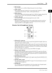
... the MONITOR OUT connectors. When this button is turned on (pushed in ), you can connect a set of stereo headphones to this jack. 01V96-Owner's Manual D PHONES LEVEL control This control sets the level of the signals output from the MONITOR OUT connectors on the rear panel. Adjust... LEVEL10 MONITOR OUT 0 LEVEL10 PHONES 5 4 A 2TR IN/OUT connectors These unbalanced RCA phono connectors input and output line-level signals, and are typically used to -40 dB when the Pad is on. 2 Control Surface & Rear Panel F PEAK indicators These indicators light up when the input signal level is...
... the MONITOR OUT connectors. When this button is turned on (pushed in ), you can connect a set of stereo headphones to this jack. 01V96-Owner's Manual D PHONES LEVEL control This control sets the level of the signals output from the MONITOR OUT connectors on the rear panel. Adjust... LEVEL10 MONITOR OUT 0 LEVEL10 PHONES 5 4 A 2TR IN/OUT connectors These unbalanced RCA phono connectors input and output line-level signals, and are typically used to -40 dB when the Pad is on. 2 Control Surface & Rear Panel F PEAK indicators These indicators light up when the input signal level is...

Owner's Manual
Page 17
... to the right of these buttons switches the Fader mode (see page 34). 01V96-Owner's Manual E Level controls These controls adjust the ST IN channel levels. The indicators to the corresponding Aux buses by using the buttons and controls in the ST IN section. B [HOME] button This... (Bus Out, Aux Out, Stereo Out) levels (see page 33), and displays the corresponding Aux page. (The selected button's indicator lights up.) You can control using the faders. FADER MODE Section 1 2 FADER MODE AUX 1 AUX 2 AUX 3 AUX 4 AUX 5 AUX 6 AUX 7 AUX 8 HOME (METER) A [AUX 1]-[AUX 8] buttons...
... to the right of these buttons switches the Fader mode (see page 34). 01V96-Owner's Manual E Level controls These controls adjust the ST IN channel levels. The indicators to the corresponding Aux buses by using the buttons and controls in the ST IN section. B [HOME] button This... (Bus Out, Aux Out, Stereo Out) levels (see page 33), and displays the corresponding Aux page. (The selected button's indicator lights up.) You can control using the faders. FADER MODE Section 1 2 FADER MODE AUX 1 AUX 2 AUX 3 AUX 4 AUX 5 AUX 6 AUX 7 AUX 8 HOME (METER) A [AUX 1]-[AUX 8] buttons...
Owner's Manual
Page 18
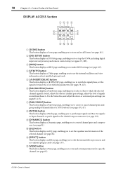
...enabling you to switch the signal phase, set the signal to be inserted, or set mix parameters for a specific channel (see page 87). 01V96-Owner's Manual 18 Chapter 2-Control Surface & Rear Panel DISPLAY ACCESS Section 1 23 4 DISPLAY ACCESS 6 5 SCENE DIO/SETUP MIDI UTILITY / INSERT/ ...84). I [DYNAMICS] button This button displays a Dynamics page, enabling you to use optional plug-in cards (see page 81). K [EFFECT] button This button displays an Effect page, enabling you to set up the 01V96, including digital input and output setup and remote control setup (see pages 85, ...
...enabling you to switch the signal phase, set the signal to be inserted, or set mix parameters for a specific channel (see page 87). 01V96-Owner's Manual 18 Chapter 2-Control Surface & Rear Panel DISPLAY ACCESS Section 1 23 4 DISPLAY ACCESS 6 5 SCENE DIO/SETUP MIDI UTILITY / INSERT/ ...84). I [DYNAMICS] button This button displays a Dynamics page, enabling you to use optional plug-in cards (see page 81). K [EFFECT] button This button displays an Effect page, enabling you to set up the 01V96, including digital input and output setup and remote control setup (see pages 85, ...
Owner's Manual
Page 19
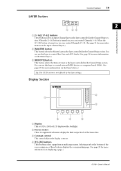
...buttons displays the corresponding page. (See page 28 for more information on displaying a page.) 01V96-Owner's Manual C Contrast control This control adjusts the display contrast. Selecting a tab at the bottom of the screen using one of the Stereo Bus. D [F1]-[F4] buttons These buttons select a page from... a multi-page screen. You can use this layer to control Bus Outs and AUX Sends. (See page 31 for ...
...buttons displays the corresponding page. (See page 28 for more information on displaying a page.) 01V96-Owner's Manual C Contrast control This control adjusts the display contrast. Selecting a tab at the bottom of the screen using one of the Stereo Bus. D [F1]-[F4] buttons These buttons select a page from... a multi-page screen. You can use this layer to control Bus Outs and AUX Sends. (See page 31 for ...
Owner's Manual
Page 20
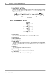
... the [SEL] button. The corresponding button indicator of the channel selected by the [SEL] button. H [GAIN] control This control adjusts the currently-selected band gain. 01V96-Owner's Manual B [HIGH] button C [HIGH-MID] button D [LOW-MID] button E [LOW] button These buttons select the EQ band (HIGH, HIGH-MID, LOW-...than the four whose tabs are available only when the left or right Tab Scroll arrow appears. These buttons are currently displayed, use these buttons to display the additional tabs. G [FREQUENCY] control This control adjusts the currently-selected band frequency.
... the [SEL] button. The corresponding button indicator of the channel selected by the [SEL] button. H [GAIN] control This control adjusts the currently-selected band gain. 01V96-Owner's Manual B [HIGH] button C [HIGH-MID] button D [LOW-MID] button E [LOW] button These buttons select the EQ band (HIGH, HIGH-MID, LOW-...than the four whose tabs are available only when the left or right Tab Scroll arrow appears. These buttons are currently displayed, use these buttons to display the additional tabs. G [FREQUENCY] control This control adjusts the currently-selected band frequency.
Owner's Manual
Page 23
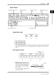
You can select signals using the Monitor Source selector. 1/4" TRS phone plug Tip (hot) Ring (cold) Sleeve (ground) 01V96-Owner's Manual Rear Panel PHANTOM +48V (p. 23) AD Output Section (p. 23) Rear Panel 23 Digital I/O Section MIDI/Control Section (p. 24) (p. 25) 2 Control Surface & Rear Panel ...
You can select signals using the Monitor Source selector. 1/4" TRS phone plug Tip (hot) Ring (cold) Sleeve (ground) 01V96-Owner's Manual Rear Panel PHANTOM +48V (p. 23) AD Output Section (p. 23) Rear Panel 23 Digital I/O Section MIDI/Control Section (p. 24) (p. 25) 2 Control Surface & Rear Panel ...
Owner's Manual
Page 24
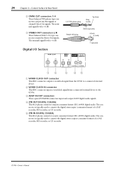
... CLOCK IN connector This BNC connector inputs a wordclock signal from the 01V96 to the 01V96. C ADAT IN/OUT connectors These optical TOSLINK connectors input and output ADAT digital audio signals. The connector is typically used to connect the digital stereo output (consumer format) of a DAT recorder... connector outputs consumer format (IEC-60958) digital audio. The connector is typically used to connect the digital stereo input (consumer format) of a DAT recorder, MD recorder, or CD recorder. 01V96-Owner's Manual E 2TR IN DIGITAL COAXIAL This RCA phono connector accepts consumer ...
... CLOCK IN connector This BNC connector inputs a wordclock signal from the 01V96 to the 01V96. C ADAT IN/OUT connectors These optical TOSLINK connectors input and output ADAT digital audio signals. The connector is typically used to connect the digital stereo output (consumer format) of a DAT recorder... connector outputs consumer format (IEC-60958) digital audio. The connector is typically used to connect the digital stereo input (consumer format) of a DAT recorder, MD recorder, or CD recorder. 01V96-Owner's Manual E 2TR IN DIGITAL COAXIAL This RCA phono connector accepts consumer ...
Owner's Manual
Page 26
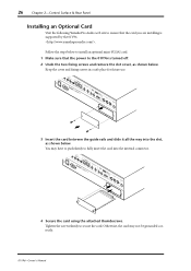
You may not be grounded correctly. 01V96-Owner's Manual Keep the cover and fixing screws in a safe place for future use. 3 Insert the card between the guide rails and slide it all the way into the internal connector. 4 Secure the card using the attached thumbscrews. Follow the steps below to install an optional...;rmly to fully insert the card into the slot, as shown below . 26 Chapter 2-Control Surface & Rear Panel Installing an Optional Card Visit the following Yamaha Pro Audio web site to ensure that the power to the...
You may not be grounded correctly. 01V96-Owner's Manual Keep the cover and fixing screws in a safe place for future use. 3 Insert the card between the guide rails and slide it all the way into the internal connector. 4 Secure the card using the attached thumbscrews. Follow the steps below to install an optional...;rmly to fully insert the card into the slot, as shown below . 26 Chapter 2-Control Surface & Rear Panel Installing an Optional Card Visit the following Yamaha Pro Audio web site to ensure that the power to the...

Owner's Manual
Page 27
...-mLAN card. D EDIT indicator This indicator appears when the current mix settings no longer match those of the currently-selected Scene memory (see page 135). 01V96-Owner's Manual The second four characters are the Channel ID (e.g., CH1-CH32, BUS1-BUS8, AUX1-AUX8, ST-L, ST-R). About the Display 3 The top panel...Scroll arrows A Selected DISPLAY This section indicates the currently-selected display page group. Operating Basics 27 3 Operating Basics This chapter describes basic operations on the 01V96, including how to use the display and operate the controls on the top panel.
...-mLAN card. D EDIT indicator This indicator appears when the current mix settings no longer match those of the currently-selected Scene memory (see page 135). 01V96-Owner's Manual The second four characters are the Channel ID (e.g., CH1-CH32, BUS1-BUS8, AUX1-AUX8, ST-L, ST-R). About the Display 3 The top panel...Scroll arrows A Selected DISPLAY This section indicates the currently-selected display page group. Operating Basics 27 3 Operating Basics This chapter describes basic operations on the 01V96, including how to use the display and operate the controls on the top panel.

Owner's Manual
Page 29
... You can change in this type of two options or to execute certain functions. Tip: The 01V96 remembers the current page and parameter when you can also select a page by using the controls or buttons on the top panel (see page 226). 3 Display Interface This section ...page group, the 01V96 displays the correct page, with the same parameter selected. Operating Basics Rotary Controls & Faders The rotary controls and faders enable you to select one of parameter box, the value flashes. Parameter Boxes The parameter boxes enable you to use the display interface...
... You can change in this type of two options or to execute certain functions. Tip: The 01V96 remembers the current page and parameter when you can also select a page by using the controls or buttons on the top panel (see page 226). 3 Display Interface This section ...page group, the 01V96 displays the correct page, with the same parameter selected. Operating Basics Rotary Controls & Faders The rotary controls and faders enable you to select one of parameter box, the value flashes. Parameter Boxes The parameter boxes enable you to use the display interface...


