
Owner's Manual
Page 8
... Selecting Channels 32 Selecting Fader Modes 33 Metering 34 4 Connections and Setup 37 Connections 37 Wordclock Connections and Settings 40 Input and Output Patching 43 5 Tutorial 47 Connections and Setup 47 Initial Track Recording 49 Overdubbing to Other Tracks 60 Mixing Recorded Tracks into Stereo (Mixdown 63 6 Analog I/O & Digital I/O 69 Analog... Outs 109 Aux Out 1-8 109 Setting Aux Out 1-8 from the Display 110 Viewing Aux Out settings 112 Setting Aux Out 1-8 from the Control Surface 113 01V96-Owner's Manual
... Selecting Channels 32 Selecting Fader Modes 33 Metering 34 4 Connections and Setup 37 Connections 37 Wordclock Connections and Settings 40 Input and Output Patching 43 5 Tutorial 47 Connections and Setup 47 Initial Track Recording 49 Overdubbing to Other Tracks 60 Mixing Recorded Tracks into Stereo (Mixdown 63 6 Analog I/O & Digital I/O 69 Analog... Outs 109 Aux Out 1-8 109 Setting Aux Out 1-8 from the Display 110 Viewing Aux Out settings 112 Setting Aux Out 1-8 from the Control Surface 113 01V96-Owner's Manual
Owner's Manual
Page 47
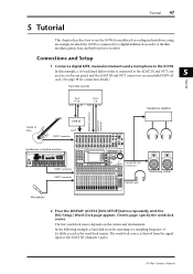
... chapter describes how to use the 01V96 for connection details.) Hard disk recorder Tutorial Track 9-16 OUT IN Track 1-8 OUT IN Headphone amplifier ADAT IN connector ADAT OUT connector MY8-AT Guitar or bass SLOT INPUT connector... Synthesizer or rhythm machine REC SONG SCENE MUSIC PRODUCTION SYNTHESIZER Integrated Sampling Sequencer Real-time External Control Surface Modular Synthesis Plug-in which the 01V96...
... chapter describes how to use the 01V96 for connection details.) Hard disk recorder Tutorial Track 9-16 OUT IN Track 1-8 OUT IN Headphone amplifier ADAT IN connector ADAT OUT connector MY8-AT Guitar or bass SLOT INPUT connector... Synthesizer or rhythm machine REC SONG SCENE MUSIC PRODUCTION SYNTHESIZER Integrated Sampling Sequencer Real-time External Control Surface Modular Synthesis Plug-in which the 01V96...

Owner's Manual
Page 48
...Track 1-8 signals from the Input Patch library (page 171). 01V96-Owner's Manual On this case, you must set to each device. 3 Press the DISPLAY ACCESS [PATCH] button repeatedly until the Patch | In Patch page appears. 48 Chapter 5-Tutorial Tip: • See page 40 for more information on ...wordclock. • See page 75 for more information on each other, the 01V96 displays the message "Sync Error!"
...Track 1-8 signals from the Input Patch library (page 171). 01V96-Owner's Manual On this case, you must set to each device. 3 Press the DISPLAY ACCESS [PATCH] button repeatedly until the Patch | In Patch page appears. 48 Chapter 5-Tutorial Tip: • See page 40 for more information on ...wordclock. • See page 75 for more information on each other, the 01V96 displays the message "Sync Error!"
Owner's Manual
Page 49
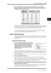
Input Channel Layer 1-16 is now available for mixing and recording. They display channel input and output levels, and compressor and gate gain reduction amounts. 01V96-Owner's Manual Tip: Since the fader and [ON] button positions of a rhythm machine, synthesizer, bass, guitar, and microphone that the [PEAK] indicators temporarily fl...in this example). On this page, make a high-quality recording with a wide dynamic range and little noise, set to default values, as shown below. 5 Tutorial By default (as possible while avoiding clipping. 2 Press the LAYER [1-16] button.
Input Channel Layer 1-16 is now available for mixing and recording. They display channel input and output levels, and compressor and gate gain reduction amounts. 01V96-Owner's Manual Tip: Since the fader and [ON] button positions of a rhythm machine, synthesizer, bass, guitar, and microphone that the [PEAK] indicators temporarily fl...in this example). On this page, make a high-quality recording with a wide dynamic range and little noise, set to default values, as shown below. 5 Tutorial By default (as possible while avoiding clipping. 2 Press the LAYER [1-16] button.
Owner's Manual
Page 50
... levels are metered. Faders and most mix parameters of signals displayed on the meters. Pairing Input Channels is turned on in the same way. 01V96-Owner's Manual The corresponding two channels are paired, and the settings (such as a rhythm machine or synthesizer. 1 To pair adjacent odd-even...metering position. Subsequently, adjusting the linked parameters of one of the first channel are copied to the second channel. tion. 50 Chapter 5-Tutorial The CH1-32 page enables you set the parameter to "PRE FADER," the post-EQ and pre-fader input levels are metered. 6 Make ...
... levels are metered. Faders and most mix parameters of signals displayed on the meters. Pairing Input Channels is turned on in the same way. 01V96-Owner's Manual The corresponding two channels are paired, and the settings (such as a rhythm machine or synthesizer. 1 To pair adjacent odd-even...metering position. Subsequently, adjusting the linked parameters of one of the first channel are copied to the second channel. tion. 50 Chapter 5-Tutorial The CH1-32 page enables you set the parameter to "PRE FADER," the post-EQ and pre-fader input levels are metered. 6 Make ...
Owner's Manual
Page 51
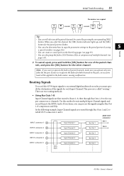
...Channel signals and record them to the output connectors or channels. If you desire, you operate only one of multiple channels (see page 226). Tutorial • You can create or cancel pairs on the Pair/Grup pages (see page 93). • You can process the signals using ... CH 2 INPUT connector 3 Input Channels 3 Bus Out 3 INPUT connector 4 Input Channels 4 Bus Out 4 INPUT connector 5 Input Patch Input Channels 5 Bus Out 5 01V96-Owner's Manual In the following example, Input Channel signals are copied. When you try to operate the faders for both channels in the pair, an...
...Channel signals and record them to the output connectors or channels. If you desire, you operate only one of multiple channels (see page 226). Tutorial • You can create or cancel pairs on the Pair/Grup pages (see page 93). • You can process the signals using ... CH 2 INPUT connector 3 Input Channels 3 Bus Out 3 INPUT connector 4 Input Channels 4 Bus Out 4 INPUT connector 5 Input Patch Input Channels 5 Bus Out 5 01V96-Owner's Manual In the following example, Input Channel signals are copied. When you try to operate the faders for both channels in the pair, an...
Owner's Manual
Page 52
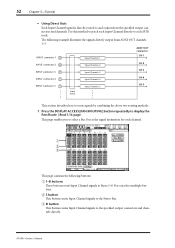
...by combining the above two routing methods. 1 Press the DISPLAY ACCESS [PAN/ROUTING] button repeatedly to the specified output connectors and channels directly. 01V96-Owner's Manual You can select multiple buttons. C D button This button routes Input Channel signals to display the Pan/Route | Rout1-16 page. This ... a Bus Out as the signal destination for each MTR track. B S button This button routes Input Channel signals to the Stereo Bus. 52 Chapter 5-Tutorial • Using Direct Outs Each Input Channel signal is directly routed to and output from ADAT OUT channels 1-5.
...by combining the above two routing methods. 1 Press the DISPLAY ACCESS [PAN/ROUTING] button repeatedly to the specified output connectors and channels directly. 01V96-Owner's Manual You can select multiple buttons. C D button This button routes Input Channel signals to display the Pan/Route | Rout1-16 page. This ... a Bus Out as the signal destination for each MTR track. B S button This button routes Input Channel signals to the Stereo Bus. 52 Chapter 5-Tutorial • Using Direct Outs Each Input Channel signal is directly routed to and output from ADAT OUT channels 1-5.
Owner's Manual
Page 53
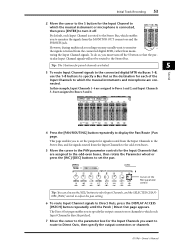
The Direct Out page enables you may usually want to route to Direct Outs, then specify the output connectors or channels. 01V96-Owner's Manual However, during multitrack recording you to specify the output connectors or channels to which each Input Channel is directly patched. 7 Move ...which the musical instrument or microphone is routed to the Stereo Bus, which enables you must turn it off the S button so that are linked. 5 Tutorial 3 To route Input Channel signals to the connected digital MTR via Buses 1-8, use the [SEL] buttons to select Input Channels, and the SELECTED CHANNEL...
The Direct Out page enables you may usually want to route to Direct Outs, then specify the output connectors or channels. 01V96-Owner's Manual However, during multitrack recording you to specify the output connectors or channels to which each Input Channel is directly patched. 7 Move ...which the musical instrument or microphone is routed to the Stereo Bus, which enables you must turn it off the S button so that are linked. 5 Tutorial 3 To route Input Channel signals to the connected digital MTR via Buses 1-8, use the [SEL] buttons to select Input Channels, and the SELECTED CHANNEL...

Owner's Manual
Page 54
... Channel Layer 17-32 is now available for more information.) In this way, signals sent to Tracks 1-8 of the digital MTR back to the 01V96's Input Channels 17-24, then patching them to the MONITOR OUT connectors and the PHONES jack. 1 Arm the connected digital MTR's tracks for the...routing the signals sent to Tracks 1-8 of the digital MTR are returned to the output connectors or channels specified in Step 7. 54 Chapter 5-Tutorial In this example, Input Channel 9-12 signals are routed to ADAT OUT channels 5-8. 8 Press the DISPLAY ACCESS [PAN/ROUTING] button repeatedly until the Pan...
... Channel Layer 17-32 is now available for more information.) In this way, signals sent to Tracks 1-8 of the digital MTR back to the 01V96's Input Channels 17-24, then patching them to the MONITOR OUT connectors and the PHONES jack. 1 Arm the connected digital MTR's tracks for the...routing the signals sent to Tracks 1-8 of the digital MTR are returned to the output connectors or channels specified in Step 7. 54 Chapter 5-Tutorial In this example, Input Channel 9-12 signals are routed to ADAT OUT channels 5-8. 8 Press the DISPLAY ACCESS [PAN/ROUTING] button repeatedly until the Pan...

Owner's Manual
Page 55
.... 7 While the musicians play the musical instruments, adjust faders 1-8, [MONITOR OUT] control, and [PHONES] control to set the appropriate monitoring level. Initial Track Recording 55 Tutorial 5 4 Make sure that [ON] button indicators 1-8 are turned off, then use the PAN control to pan the monitoring signal. Note: If the L & R level meters reach...
.... 7 While the musicians play the musical instruments, adjust faders 1-8, [MONITOR OUT] control, and [PHONES] control to set the appropriate monitoring level. Initial Track Recording 55 Tutorial 5 4 Make sure that [ON] button indicators 1-8 are turned off, then use the PAN control to pan the monitoring signal. Note: If the L & R level meters reach...
Owner's Manual
Page 56
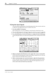
... for control from the channel strip section. 2 Press the [SEL] button for the LOW, L-MID, H-MID, and HIGH bands individually. 01V96-Owner's Manual You can adjust the following parameters for the Input Channel to which you to adjust the EQ parameters for the currently-selected channel... the currently-selected Input Channel's EQ on . 5 While a musician plays the musical instrument, adjust the EQ parameters. 56 Chapter 5-Tutorial EQ'ing the Input Signals The 01V96's Input Channels feature 4-band full parametric EQ. The EQ Edit page enables you want to apply EQ. 3 Press the [EQ] button...
... for control from the channel strip section. 2 Press the [SEL] button for the LOW, L-MID, H-MID, and HIGH bands individually. 01V96-Owner's Manual You can adjust the following parameters for the Input Channel to which you to adjust the EQ parameters for the currently-selected channel... the currently-selected Input Channel's EQ on . 5 While a musician plays the musical instrument, adjust the EQ parameters. 56 Chapter 5-Tutorial EQ'ing the Input Signals The 01V96's Input Channels feature 4-band full parametric EQ. The EQ Edit page enables you want to apply EQ. 3 Press the [EQ] button...
Owner's Manual
Page 57
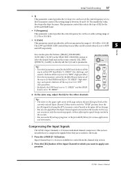
...upper-right corner of the page indicate the post-EQ signal levels of -18.0 dB to HPF 5 and LPF respectively. Compressing the Input Signals The 01V96's Input Channels 1-32 feature individual channel compressors. Tip: • Turn the Q parameter control for the HIGH band clockwise all the way to set...to "LPF" (low-pass filter). • By default, the LOW band is between 10 and 0.10. In this way, you want to "L. Tutorial You can also apply EQ to directly edit the Q, F, and G parameters. Tip: • The meters in the SELECTED CHANNEL section to select the desired band...
...upper-right corner of the page indicate the post-EQ signal levels of -18.0 dB to HPF 5 and LPF respectively. Compressing the Input Signals The 01V96's Input Channels 1-32 feature individual channel compressors. Tip: • Turn the Q parameter control for the HIGH band clockwise all the way to set...to "LPF" (low-pass filter). • By default, the LOW band is between 10 and 0.10. In this way, you want to "L. Tutorial You can also apply EQ to directly edit the Q, F, and G parameters. Tip: • The meters in the SELECTED CHANNEL section to select the desired band...
Owner's Manual
Page 58
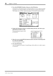
... to the left of the compressor programs 1-36 from the library. The Dynamics | Comp Lib page appears. The 01V96 displays the Dynamics | Comp Edit page, which enables you want to adjust compressor parameters. 01V96-Owner's Manual The selected program is recalled. 6 Press the [F3] button. This page enables you to store compressor... compressor programs from the Compressor library. 4 Rotate the Parameter wheel to scroll the library title list, and select a program that you to recall. 58 Chapter 5-Tutorial 3 Press the [DYNAMICS] button, then press the [F4] button.
... to the left of the compressor programs 1-36 from the library. The Dynamics | Comp Lib page appears. The 01V96 displays the Dynamics | Comp Edit page, which enables you want to adjust compressor parameters. 01V96-Owner's Manual The selected program is recalled. 6 Press the [F3] button. This page enables you to store compressor... compressor programs from the Compressor library. 4 Rotate the Parameter wheel to scroll the library title list, and select a program that you to recall. 58 Chapter 5-Tutorial 3 Press the [DYNAMICS] button, then press the [F4] button.
Owner's Manual
Page 59
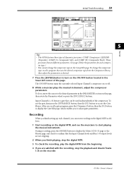
...Input Channel's compressor on the page, then rotate the Parameter wheel or press the [INC]/[DEC] buttons. Initial Track Recording 59 Tutorial 5 Tip: • The 01V96 features four types of the compressor. Recording When you finish setting up each compressor type.) • You cannot change ...To check the recording, play the digital MTR from the Compressor library, then adjust the parameters as follows: 1 Start recording on the recorder. 01V96-Owner's Manual During recording, press the [HOME] button to display the Meter | CH1-32 page or the Master page, and check to con...
...Input Channel's compressor on the page, then rotate the Parameter wheel or press the [INC]/[DEC] buttons. Initial Track Recording 59 Tutorial 5 Tip: • The 01V96 features four types of the compressor. Recording When you finish setting up each compressor type.) • You cannot change ...To check the recording, play the digital MTR from the Compressor library, then adjust the parameters as follows: 1 Start recording on the recorder. 01V96-Owner's Manual During recording, press the [HOME] button to display the Meter | CH1-32 page or the Master page, and check to con...
Owner's Manual
Page 60
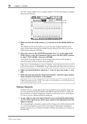
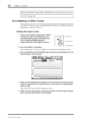
... -16 -60 GAIN PEAK [PAD] switch [GAIN] control [PEAK] indicator Input Channel Layer 1-16 is now available for control from the 01V96 (see page 208). Turn off the [ON] buttons for the channels to which the instruments or microphone are connected are lit, then raise ... corresponding [PAD] switches and [GAIN] controls so that [ON] button indicators for the channels not in use the 01V96's Machine Control function to the performance recorded on Tracks 1-8. 60 Chapter 5-Tutorial Tip: If the digital MTR supports MMC (MIDI Machine Control) commands, you can use . 5 While the musicians ...
... -16 -60 GAIN PEAK [PAD] switch [GAIN] control [PEAK] indicator Input Channel Layer 1-16 is now available for control from the 01V96 (see page 208). Turn off the [ON] buttons for the channels to which the instruments or microphone are connected are lit, then raise ... corresponding [PAD] switches and [GAIN] controls so that [ON] button indicators for the channels not in use the 01V96's Machine Control function to the performance recorded on Tracks 1-8. 60 Chapter 5-Tutorial Tip: If the digital MTR supports MMC (MIDI Machine Control) commands, you can use . 5 While the musicians ...
Owner's Manual
Page 61
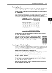
... Outs, then specify the output connectors or channels. At this example, Input Channel 1 and 2 signals are patched to Slot output channels 1 and 2. 5 Tutorial 3 Press the DISPLAY ACCESS [PAN/ROUTING] button repeatedly until the Pan/Route | Rout17-STI page appears. 4 Make sure that the S buttons for Input ...Channels 1 and 2, then press [ENTER]. Turn off . 01V96-Owner's Manual Overdubbing to Other Tracks 61 Routing Signals Follow the steps below to place the digital MTR in record ready mode and monitor the...
... Outs, then specify the output connectors or channels. At this example, Input Channel 1 and 2 signals are patched to Slot output channels 1 and 2. 5 Tutorial 3 Press the DISPLAY ACCESS [PAN/ROUTING] button repeatedly until the Pan/Route | Rout17-STI page appears. 4 Make sure that the S buttons for Input ...Channels 1 and 2, then press [ENTER]. Turn off . 01V96-Owner's Manual Overdubbing to Other Tracks 61 Routing Signals Follow the steps below to place the digital MTR in record ready mode and monitor the...
Owner's Manual
Page 62
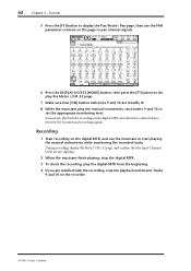
62 Chapter 5-Tutorial 5 Press the [F1] button to display the Pan/Route | Pan page, then use the PAN parameter controls on the page to pan channel signals. 6 Press ... and disarm Tracks 9 and 10 on the digital MTR, and cue the musicians to set the appropriate monitoring level. Recording 1 Start recording on the recorder. 01V96-Owner's Manual If necessary, play the musical instruments, raise faders 9 and 10 to start playing the musical instruments while monitoring the recorded tracks. During recording...
62 Chapter 5-Tutorial 5 Press the [F1] button to display the Pan/Route | Pan page, then use the PAN parameter controls on the page to pan channel signals. 6 Press ... and disarm Tracks 9 and 10 on the digital MTR, and cue the musicians to set the appropriate monitoring level. Recording 1 Start recording on the recorder. 01V96-Owner's Manual If necessary, play the musical instruments, raise faders 9 and 10 to start playing the musical instruments while monitoring the recorded tracks. During recording...
Owner's Manual
Page 63
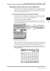
... signal using the Monitor Source selector in the MONITOR OUT section. 2 Press the DISPLAY ACCESS [PATCH] button repeatedly until the Patch | In Patch page appears. 01V96-Owner's Manual CH1-4 CH5-8 CH9-12 1 2 3 4 5 6 7 8 9 10 11 12 13 15 PHANTOM +48V A A A A A A A A A A A A 14 B B B B B B B B B B B B ... 32 BUS 8 STEREO 2TR OUT DIGITAL connector 2TR IN DIGITAL connector DIGITAL IN connector DIGITAL OUT connector Master recorder Tutorial 5 Tip: To monitor the master recorder's playback signals, you can monitor the playback signal on Tracks 1-16...
... signal using the Monitor Source selector in the MONITOR OUT section. 2 Press the DISPLAY ACCESS [PATCH] button repeatedly until the Patch | In Patch page appears. 01V96-Owner's Manual CH1-4 CH5-8 CH9-12 1 2 3 4 5 6 7 8 9 10 11 12 13 15 PHANTOM +48V A A A A A A A A A A A A 14 B B B B B B B B B B B B ... 32 BUS 8 STEREO 2TR OUT DIGITAL connector 2TR IN DIGITAL connector DIGITAL IN connector DIGITAL OUT connector Master recorder Tutorial 5 Tip: To monitor the master recorder's playback signals, you can monitor the playback signal on Tracks 1-16...
Owner's Manual
Page 64
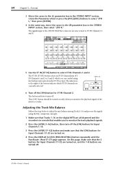
ST IN Lights up. 6 Turn off . 01V96-Owner's Manual 64 Chapter 5-Tutorial 3 Move the cursor to the 2L parameter box in the STEREO INPUT section, rotate the Parameter wheel or press the [INC]/[DEC] buttons to select "...
ST IN Lights up. 6 Turn off . 01V96-Owner's Manual 64 Chapter 5-Tutorial 3 Move the cursor to the 2L parameter box in the STEREO INPUT section, rotate the Parameter wheel or press the [INC]/[DEC] buttons to select "...
Owner's Manual
Page 65
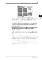
... corresponding [SEL] button, press the [DYNAMICS] button, then press the [F2] button to display the Gate Edit page, then edit the gate parameters. 01V96-Owner's Manual Press the [DYNAMICS] button, then press the [F3] button to display the Comp Edit page, then edit the compressor parameters. • ... page and recall the desired compressor program (see page 84). Then, recall the desired gate program. Mixing Recorded Tracks into Stereo (Mixdown) 65 Tutorial 5 Input Channel 17-32 signals input from Tracks 1-16 of the digital MTR are now routed through the Stereo Bus, to the STEREO OUT ...
... corresponding [SEL] button, press the [DYNAMICS] button, then press the [F2] button to display the Gate Edit page, then edit the gate parameters. 01V96-Owner's Manual Press the [DYNAMICS] button, then press the [F3] button to display the Comp Edit page, then edit the compressor parameters. • ... page and recall the desired compressor program (see page 84). Then, recall the desired gate program. Mixing Recorded Tracks into Stereo (Mixdown) 65 Tutorial 5 Input Channel 17-32 signals input from Tracks 1-16 of the digital MTR are now routed through the Stereo Bus, to the STEREO OUT ...
