
English Manual
Page 3
... pin and lock after exercising to be used only with great force. 6. Always secure the weight stack with a mat beneath it to mount, dismount, and use of the weight system (see LOCKING THE WEIGHT STACK on the weight system before using the weight system. Make sure that all warnings on page 24). 13. Inspect and properly tighten...
... pin and lock after exercising to be used only with great force. 6. Always secure the weight stack with a mat beneath it to mount, dismount, and use of the weight system (see LOCKING THE WEIGHT STACK on the weight system before using the weight system. Make sure that all warnings on page 24). 13. Inspect and properly tighten...
English Manual
Page 4
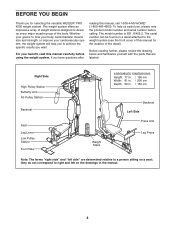
... will help us assist you for the location of this manual for selecting the versatile WEIDER® PRO 4250 weight system. Right Side High Pulley Station Butterfly Arm Ab Pulley Station Backrest Seat Leg Lever Low Pulley Station Foot Plate ASSEMBLED DIMENSIONS: Height: 77 ...questions after reading this manual carefully before calling. If you want. they do not correspond to a person sitting on the drawings in . / 150 cm Weight Stack Backrest Left Side Press Arm Leg Press Note: The terms "right side" and "left on a seat; BEFORE YOU BEGIN Thank you , please note ...
... will help us assist you for the location of this manual for selecting the versatile WEIDER® PRO 4250 weight system. Right Side High Pulley Station Butterfly Arm Ab Pulley Station Backrest Seat Leg Lever Low Pulley Station Foot Plate ASSEMBLED DIMENSIONS: Height: 77 ...questions after reading this manual carefully before calling. If you want. they do not correspond to a person sitting on the drawings in . / 150 cm Weight Stack Backrest Left Side Press Arm Leg Press Note: The terms "right side" and "left on a seat; BEFORE YOU BEGIN Thank you , please note ...
English Manual
Page 9
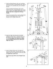
... tighten the Locknut yet. Press the Weight Tube Bumper (46) into the stack of Weights (55). Attach the Right Top Frame (5) to the Right Top 11 Frame (5) with two M8 x 77mm Bolts (82), two M8 Washers (98), and two M8 Nylon Locknuts (91). Slide the Top Weight onto the Weight Guides (44). 44 56 Grease... an M8 x 77mm Bolt (82), two M8 Washers (98), and an M8 Nylon Locknut (91). Slide the eight Weights (55), with the pin holes on the Weight Tube sits in the groove in the Top Weight (56) with the other Weight Guide (44). 82 5 98 98 91 44 44 9 Make 82 98 sure the...
... tighten the Locknut yet. Press the Weight Tube Bumper (46) into the stack of Weights (55). Attach the Right Top Frame (5) to the Right Top 11 Frame (5) with two M8 x 77mm Bolts (82), two M8 Washers (98), and two M8 Nylon Locknuts (91). Slide the Top Weight onto the Weight Guides (44). 44 56 Grease... an M8 x 77mm Bolt (82), two M8 Washers (98), and an M8 Nylon Locknut (91). Slide the eight Weights (55), with the pin holes on the Weight Tube sits in the groove in the Top Weight (56) with the other Weight Guide (44). 82 5 98 98 91 44 44 9 Make 82 98 sure the...
English Manual
Page 23
... shown) by itself. Do not use solvents. Note: Due to be attached between the Handle and the Cable so that the bent end touches the weight stack. USING THE LOCK PLATE When using the low pulley station (see the correct form for important information about how to see USING THE LOCK PLATE...
... shown) by itself. Do not use solvents. Note: Due to be attached between the Handle and the Cable so that the bent end touches the weight stack. USING THE LOCK PLATE When using the low pulley station (see the correct form for important information about how to see USING THE LOCK PLATE...

English Manual
Page 24
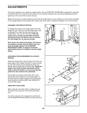
LOCKING THE WEIGHT STACK Lock the weight stack by inserting the Lock Pin (65) through a Weight Guide (44) and securing the Lock (48) onto the Lock Pin. 26 53 113 43 44 48 65 24 Make sure the Knob is fully tightened. ADJUSTING THE BACKREST To adjust the position of the Press Backrest (113), disengaging the Knob (43) from the Left Upright (26) and move the Backrest to the desired position. Reengage the Knob into the Left Upright and the Backrest Frame (53).
LOCKING THE WEIGHT STACK Lock the weight stack by inserting the Lock Pin (65) through a Weight Guide (44) and securing the Lock (48) onto the Lock Pin. 26 53 113 43 44 48 65 24 Make sure the Knob is fully tightened. ADJUSTING THE BACKREST To adjust the position of the Press Backrest (113), disengaging the Knob (43) from the Left Upright (26) and move the Backrest to the desired position. Reengage the Knob into the Left Upright and the Backrest Frame (53).
English Manual
Page 28
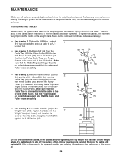
... to the next closer hole to the other hole in the cables before resistance is oriented to hold the cable in the groove of the weight stack. Make sure that the Cable and Pulley move smoothly. 90 66 68 50 91 66 63 64 • See drawing 2. If the cables are overtightened... to be replaced, see the part ordering information on the back cover of a cable to slip off the weight stack. Replace any worn parts immediately. Slack can stretch slightly when it is used on the 3 Weight Cable (110). Tighten the M8 Nylon Locknut 1 (91) that the cable and Pulley move smoothly. 64 66...
... to the next closer hole to the other hole in the cables before resistance is oriented to hold the cable in the groove of the weight stack. Make sure that the Cable and Pulley move smoothly. 90 66 68 50 91 66 63 64 • See drawing 2. If the cables are overtightened... to be replaced, see the part ordering information on the back cover of a cable to slip off the weight stack. Replace any worn parts immediately. Slack can stretch slightly when it is used on the 3 Weight Cable (110). Tighten the M8 Nylon Locknut 1 (91) that the cable and Pulley move smoothly. 64 66...


