
Uk Manual
Page 2
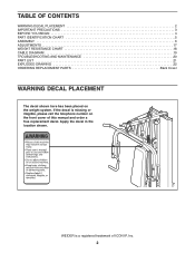
White Text/Clear Background WEIDER is missing or illegible, please call the telephone number on the weight system. Apply the decal in the location shown. If the decal is a registered trademark of this manual and order a free replacement... Background PN 218559 - TABLE OF CONTENTS WARNING DECAL PLACEMENT 2 IMPORTANT PRECAUTIONS 3 BEFORE YOU BEGIN 4 PART IDENTIFICATION CHART 5 ASSEMBLY 6 ADJUSTMENTS 17 WEIGHT RESISTANCE CHART 18 CABLE DIAGRAM 19 TROUBLESHOOTING AND MAINTENANCE 20 PART LIST 21 EXPLODED DRAWING 22 ORDERING REPLACEMENT PARTS Back Cover WARNING DECAL PLACEMENT The...
White Text/Clear Background WEIDER is missing or illegible, please call the telephone number on the weight system. Apply the decal in the location shown. If the decal is a registered trademark of this manual and order a free replacement... Background PN 218559 - TABLE OF CONTENTS WARNING DECAL PLACEMENT 2 IMPORTANT PRECAUTIONS 3 BEFORE YOU BEGIN 4 PART IDENTIFICATION CHART 5 ASSEMBLY 6 ADJUSTMENTS 17 WEIGHT RESISTANCE CHART 18 CABLE DIAGRAM 19 TROUBLESHOOTING AND MAINTENANCE 20 PART LIST 21 EXPLODED DRAWING 22 ORDERING REPLACEMENT PARTS Back Cover WARNING DECAL PLACEMENT The...
Uk Manual
Page 3
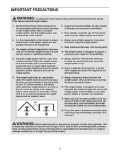
...foot plate when performing an exercise that does not use only. Inspect and properly tighten all times. 2. Place the weight system on the weight system before using . the weight stack must be accessible from moving parts. 10. If the cables bind while you feel pain or dizziness at ... children under the age of a room, as described in this or any point outside of the user's field of clearance between the weight system and the adjacent walls. IMPORTANT PRECAUTIONS WARNING: To reduce the risk of this manual and in the accompanying literature and all times....
...foot plate when performing an exercise that does not use only. Inspect and properly tighten all times. 2. Place the weight system on the weight system before using . the weight stack must be accessible from moving parts. 10. If the cables bind while you feel pain or dizziness at ... children under the age of a room, as described in this or any point outside of the user's field of clearance between the weight system and the adjacent walls. IMPORTANT PRECAUTIONS WARNING: To reduce the risk of this manual and in the accompanying literature and all times....
Uk Manual
Page 4
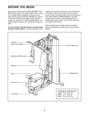
...or improve your benefit, read this manual carefully before contacting us. Whether your goal is WEEVSY2026.0. For your cardiovascular system, the weight system will help us assist you for the location of the decal). Lat Bar High Pulley Station Butterfly Arm/Press Arm Backrest... Depth: 52 in. (132 cm) 4 The model number is to the weight system (see the front cover of this manual for selecting the versatile WEIDER® PRO 2000 weight system. The weight system offers a selection of weight stations designed to achieve the results you have questions after reading this manual, see...
...or improve your benefit, read this manual carefully before contacting us. Whether your goal is WEEVSY2026.0. For your cardiovascular system, the weight system will help us assist you for the location of the decal). Lat Bar High Pulley Station Butterfly Arm/Press Arm Backrest... Depth: 52 in. (132 cm) 4 The model number is to the weight system (see the front cover of this manual for selecting the versatile WEIDER® PRO 2000 weight system. The weight system offers a selection of weight stations designed to achieve the results you have questions after reading this manual, see...
Uk Manual
Page 6
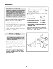
...assemble them in place. 68 1 Indent These holes are required for Yourself Everything in this manual is designed to realize that the versatile weight system has many parts and that the assembly process will go smoothly. Do not dispose of the Base (1). The following information and instructions...Locknuts yet. Before beginning assembly, carefully read and understand the information in the box above. However, it is important to ensure that the weight system can be sure that you have read the following tools (not included) are smaller than on the opposite side. 58 59 2...
...assemble them in place. 68 1 Indent These holes are required for Yourself Everything in this manual is designed to realize that the versatile weight system has many parts and that the assembly process will go smoothly. Do not dispose of the Base (1). The following information and instructions...Locknuts yet. Before beginning assembly, carefully read and understand the information in the box above. However, it is important to ensure that the weight system can be sure that you have read the following tools (not included) are smaller than on the opposite side. 58 59 2...
Uk Manual
Page 7
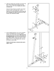
... that the indicated holes are closer to the Base (1) with the two 2 M8 x 63mm Carriage Bolts (58) and two M8 Nylon Locknuts (69). Secure the Weight Guides in place with an M8 x 63mm Bolt (66), two M8 Washers (71), and an M8 Nylon Locknut (69). Attach the Press Frame Lock (39...) to the Upright (3) with two M10 x 70mm Bolts (57), two M10 Washers (70), two Small Spacers (37), and two M10 Nylon Locknuts (68). Set two Weight Bumpers (17) over the indicated 3 holes in steps 1 and 3. 10 17 68 Holes 70 57 37 17 68 2 7 Attach the Upright (3) to the bottom of...
... that the indicated holes are closer to the Base (1) with the two 2 M8 x 63mm Carriage Bolts (58) and two M8 Nylon Locknuts (69). Secure the Weight Guides in place with an M8 x 63mm Bolt (66), two M8 Washers (71), and an M8 Nylon Locknut (69). Attach the Press Frame Lock (39...) to the Upright (3) with two M10 x 70mm Bolts (57), two M10 Washers (70), two Small Spacers (37), and two M10 Nylon Locknuts (68). Set two Weight Bumpers (17) over the indicated 3 holes in steps 1 and 3. 10 17 68 Holes 70 57 37 17 68 2 7 Attach the Upright (3) to the bottom of...
Uk Manual
Page 8
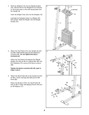
Attach the Top Frame (4) to the Seat Frame (8) with 5 two M8 x 68mm Bolts (63) and two M8 Nylon Locknuts (69). Slide ten Weights (15) onto the Weight Guides 4 (10), with grease. Lubricate the indicated holes in steps 2 and 5. 4 62 70 63 3 69 10 70 68 6. Attach the Bumper (75) ...62), two M10 Washers (70), and an M10 Nylon Locknut (68). Insert the Weight Tube (12) into the Weights (15). Slide the Weight onto the Weight Guides (10). 10 Lubricate 15 3 12 15 5. Attach the Top Frame (4) between the Weight Guides (10) with an M8 x 70mm Carriage Bolt (86) and an M8 ...
Attach the Top Frame (4) to the Seat Frame (8) with 5 two M8 x 68mm Bolts (63) and two M8 Nylon Locknuts (69). Slide ten Weights (15) onto the Weight Guides 4 (10), with grease. Lubricate the indicated holes in steps 2 and 5. 4 62 70 63 3 69 10 70 68 6. Attach the Bumper (75) ...62), two M10 Washers (70), and an M10 Nylon Locknut (68). Insert the Weight Tube (12) into the Weights (15). Slide the Weight onto the Weight Guides (10). 10 Lubricate 15 3 12 15 5. Attach the Top Frame (4) between the Weight Guides (10) with an M8 x 70mm Carriage Bolt (86) and an M8 ...
Uk Manual
Page 11
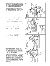
... Left Arm (7). Hook 49 17. Wrap the Press Cable (49) over a 90mm Pulley 14 (34). Attach the Pulley and two Finger Guards (35) to the Weight Tube (12) with an M10 x 46mm Bolt (53) and an M10 Nylon Locknut (68). Attach the Small "U"-bracket (11) to the Top Frame (4) with an... Pulley Arm (38) to hold the Cable in the groove of the Pulley. 11 7 54 35 36 68 38 52 34 35 70 3 49 the Weight Tube must pivot easily. Make sure that two threads show past the Nylon Locknut, as shown in the Small "U"-bracket. 69 12 50 60 11...
... Left Arm (7). Hook 49 17. Wrap the Press Cable (49) over a 90mm Pulley 14 (34). Attach the Pulley and two Finger Guards (35) to the Weight Tube (12) with an M10 x 46mm Bolt (53) and an M10 Nylon Locknut (68). Attach the Small "U"-bracket (11) to the Top Frame (4) with an... Pulley Arm (38) to hold the Cable in the groove of the Pulley. 11 7 54 35 36 68 38 52 34 35 70 3 49 the Weight Tube must pivot easily. Make sure that two threads show past the Nylon Locknut, as shown in the Small "U"-bracket. 69 12 50 60 11...
Uk Manual
Page 16
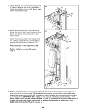
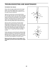
33. Attach the Left Shroud (87) to remove it by tightening the cables; Before using the weight system, pull each cable a few times to make sure that all remaining parts will need to the Left Shroud 34 Frame (85) and the Top ... one of the cables does not move smoothly over the pulleys. If there is any slack in the cables, you will be damaged when heavy weight is used in ADJUSTMENTS, on page 20. 16
33. Attach the Left Shroud (87) to remove it by tightening the cables; Before using the weight system, pull each cable a few times to make sure that all remaining parts will need to the Left Shroud 34 Frame (85) and the Top ... one of the cables does not move smoothly over the pulleys. If there is any slack in the cables, you will be damaged when heavy weight is used in ADJUSTMENTS, on page 20. 16
Uk Manual
Page 17
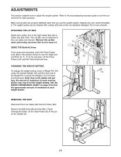
... THE LAT BAR Attach the Lat Bar (31) to lock the Right and Left Arms (6, 7). Note: The Lat Bar can be attached to adjust the weight system. Remove the Lat Bar when performing exercises that do fly exercises, lift the Press Frame Lock until the bent end of the... Weight Pin touches the Weights. To do not require it. Remove the M8 Knob (82) and the M8 x 70mm Carriage Bolt (86). ADJUSTMENTS This section explains how to the Low...
... THE LAT BAR Attach the Lat Bar (31) to lock the Right and Left Arms (6, 7). Note: The Lat Bar can be attached to adjust the weight system. Remove the Lat Bar when performing exercises that do fly exercises, lift the Press Frame Lock until the bent end of the... Weight Pin touches the Weights. To do not require it. Remove the M8 Knob (82) and the M8 x 70mm Carriage Bolt (86). ADJUSTMENTS This section explains how to the Low...
Uk Manual
Page 18
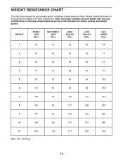
... at each station may vary due to differences in individual weight plates as well as friction between the cables, pulleys, and weight guides. Note: The actual resistance at each butterfly arm. Weight resistance shown for the butterfly arm station is for each exercise station. WEIGHT 1 PRESS ARM (lbs.) 35 BUTTERFLY ARM (lbs.) 19 HIGH...
... at each station may vary due to differences in individual weight plates as well as friction between the cables, pulleys, and weight guides. Note: The actual resistance at each butterfly arm. Weight resistance shown for the butterfly arm station is for each exercise station. WEIGHT 1 PRESS ARM (lbs.) 35 BUTTERFLY ARM (lbs.) 19 HIGH...
Uk Manual
Page 19
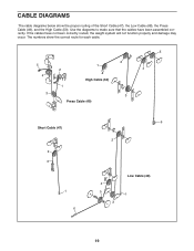
If the cables have been assembled correctly. CABLE DIAGRAMS The cable diagrams below show the correct route for each cable. 5 5 2 4 1 2 1 4 High Cable (50) 3 3 Press Cable (49) Short Cable (47) 2 3 1 6 6 2 4 5 3 Low Cable (48) 1 19 Use the diagrams to make sure that the cables have not been correctly routed, the weight system will not function properly and damage may occur. The numbers show the proper routing of the Short Cable (47), the Low Cable (48), the Press Cable (49), and the High Cable (50).
If the cables have been assembled correctly. CABLE DIAGRAMS The cable diagrams below show the correct route for each cable. 5 5 2 4 1 2 1 4 High Cable (50) 3 3 Press Cable (49) Short Cable (47) 2 3 1 6 6 2 4 5 3 Low Cable (48) 1 19 Use the diagrams to make sure that the cables have not been correctly routed, the weight system will not function properly and damage may occur. The numbers show the proper routing of the Short Cable (47), the Low Cable (48), the Press Cable (49), and the High Cable (50).
Uk Manual
Page 20
...bracket (not shown) can be tightened. If there is slack in the cables before resistance is first used on the weight system, can be removed by tightening the M8 Washer (71) and M8 Nylon Locknut (69) attaching the Short ...cables should be adjusted in the same manner. Make sure that the cables are not too tight or the Top Weight (not shown) will be removed by moving a 90mm Pulley (34), the Cable Trap (36), and two ... set of holes closer to the higher set of cable used . Slack can also be lifted off the weight stack. 52 35 36 44 35 68 34 47 43 71 52 69 68 35 36 34 35 20...
...bracket (not shown) can be tightened. If there is slack in the cables before resistance is first used on the weight system, can be removed by tightening the M8 Washer (71) and M8 Nylon Locknut (69) attaching the Short ...cables should be adjusted in the same manner. Make sure that the cables are not too tight or the Top Weight (not shown) will be removed by moving a 90mm Pulley (34), the Cable Trap (36), and two ... set of holes closer to the higher set of cable used . Slack can also be lifted off the weight stack. 52 35 36 44 35 68 34 47 43 71 52 69 68 35 36 34 35 20...
Uk Manual
Page 21
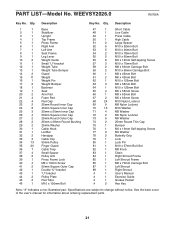
Description 1 1 Base 2 1 Stabilizer 3 1 Upright 4 1 Top Frame 5 1 Press Frame 6 1 Right Arm 7 1 Left Arm 8 1 Seat Frame 9 1 Leg Lever 10 2 Weight Guide 11 1 Small "U"-bracket 12 1 Weight Tube 13 1 Weight Tube Bumper 14 2 Guard 15 11 Weight 16 1 Weight Pin 17 2 Weight Bumper 18 1 Backrest 19 1 Seat 20 2 Arm Pad 21 4 Foam Pad 22 4 Pad Cap 23 2 25mm Round Inner...
Description 1 1 Base 2 1 Stabilizer 3 1 Upright 4 1 Top Frame 5 1 Press Frame 6 1 Right Arm 7 1 Left Arm 8 1 Seat Frame 9 1 Leg Lever 10 2 Weight Guide 11 1 Small "U"-bracket 12 1 Weight Tube 13 1 Weight Tube Bumper 14 2 Guard 15 11 Weight 16 1 Weight Pin 17 2 Weight Bumper 18 1 Backrest 19 1 Seat 20 2 Arm Pad 21 4 Foam Pad 22 4 Pad Cap 23 2 25mm Round Inner...
Uk Manual
Page 24
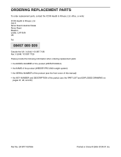
... 387 7125 Please provide the following information when ordering replacement parts: • the MODEL NUMBER of the product (WEEVSY2026.0) • the NAME of the product (WEIDER PRO 2000 weight system) • the SERIAL NUMBER of the product (see the front cover of this manual) • the KEY NUMBER and DESCRIPTION of the part(s) (see...
... 387 7125 Please provide the following information when ordering replacement parts: • the MODEL NUMBER of the product (WEEVSY2026.0) • the NAME of the product (WEIDER PRO 2000 weight system) • the SERIAL NUMBER of the product (see the front cover of this manual) • the KEY NUMBER and DESCRIPTION of the part(s) (see...


