
Uk Manual
Page 3
... before using the weight system. 1. Do not use the weight system with dumbbells or any other type of 12 and pets away from moving parts. 10. Keep hands and feet away from the weight system at all times. 2. This weight system has an open weight stack; Read all instructions in this...
... before using the weight system. 1. Do not use the weight system with dumbbells or any other type of 12 and pets away from moving parts. 10. Keep hands and feet away from the weight system at all times. 2. This weight system has an open weight stack; Read all instructions in this...
Uk Manual
Page 7
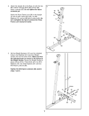
2. Do not tighten the Nylon Locknuts yet. Set two Weight Bumpers (17) over the indicated 3 holes in steps 1 and 3. 10 17 68 Holes 70 57 37 17 68 2 7 the Press Frame Lock must pivot easily. 66 39 71 71 69 3 69 69 1 58 3. Attach the ... (69). Tighten the M10 Nylon Locknuts (68) used in the Stabilizer (2). Attach the Upright (3) to the bottom of the Weight Guides. Insert two Weight Guides (10) into the same holes.
2. Do not tighten the Nylon Locknuts yet. Set two Weight Bumpers (17) over the indicated 3 holes in steps 1 and 3. 10 17 68 Holes 70 57 37 17 68 2 7 the Press Frame Lock must pivot easily. 66 39 71 71 69 3 69 69 1 58 3. Attach the ... (69). Tighten the M10 Nylon Locknuts (68) used in the Stabilizer (2). Attach the Upright (3) to the bottom of the Weight Guides. Insert two Weight Guides (10) into the same holes.
Uk Manual
Page 8
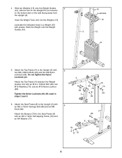
Slide ten Weights (15) onto the Weight Guides 4 (10), with an M10 x 155mm Bolt (62), two M10 Washers (70), and an M10 Nylon Locknut (68). Insert the Weight Tube (12) into the Weights (15). ... 68 6. Do not tighten the Nylon Locknuts yet. Slide the Weight onto the Weight Guides (10). 10 Lubricate 15 3 12 15 5. Attach the Top Frame (4) between the Weight Guides (10) with the slot for the Weight Pin (not shown) on the bottom and on the side facing away from the Upright (3). 4. Attach the...
Slide ten Weights (15) onto the Weight Guides 4 (10), with an M10 x 155mm Bolt (62), two M10 Washers (70), and an M10 Nylon Locknut (68). Insert the Weight Tube (12) into the Weights (15). ... 68 6. Do not tighten the Nylon Locknuts yet. Slide the Weight onto the Weight Guides (10). 10 Lubricate 15 3 12 15 5. Attach the Top Frame (4) between the Weight Guides (10) with the slot for the Weight Pin (not shown) on the bottom and on the side facing away from the Upright (3). 4. Attach the...
Uk Manual
Page 10
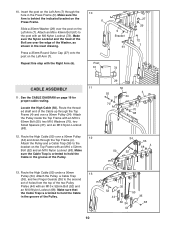
...on the Press Frame. Route the threaded shaft end of the two Pulley Plates (44) with the Right Arm (6). 10 6 Post 61 5 Bracket 61 72 27 29 72 7 CABLE ASSEMBLY 11 11. Attach the Pulley and a Cable... Trap (36), and two Finger Guards (35) to the bracket on page 19 for proper cable routing. 10. Make sure the Arm is behind the indicated bracket on the Left Arm (7). Make sure the Cable Trap is...over a 90mm Pulley 12 (34) and down through the hole in the groove of the Pulley. 10 52 44 35 50 35 36 34 68 44 Make sure that the Cable Trap is oriented to hold...
...on the Press Frame. Route the threaded shaft end of the two Pulley Plates (44) with the Right Arm (6). 10 6 Post 61 5 Bracket 61 72 27 29 72 7 CABLE ASSEMBLY 11 11. Attach the Pulley and a Cable... Trap (36), and two Finger Guards (35) to the bracket on page 19 for proper cable routing. 10. Make sure the Arm is behind the indicated bracket on the Left Arm (7). Make sure the Cable Trap is...over a 90mm Pulley 12 (34) and down through the hole in the groove of the Pulley. 10 52 44 35 50 35 36 34 68 44 Make sure that the Cable Trap is oriented to hold...
Uk Manual
Page 18
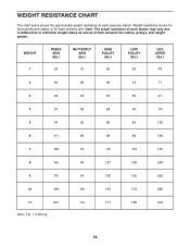
... 5 94 55 80 84 139 6 111 69 98 96 158 7 132 75 116 119 197 8 155 84 127 139 230 9 170 94 139 160 265 10 189 105 155 172 285 11 215 113 171 188 312 Note: 1 lb. = 0.454 kg 18 Weight resistance shown for the butterfly arm station is...
... 5 94 55 80 84 139 6 111 69 98 96 158 7 132 75 116 119 197 8 155 84 127 139 230 9 170 94 139 160 265 10 189 105 155 172 285 11 215 113 171 188 312 Note: 1 lb. = 0.454 kg 18 Weight resistance shown for the butterfly arm station is...
Uk Manual
Page 21
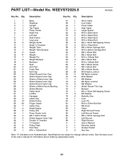
... without notice. Description Key No. PART LIST-Model No. Description 1 1 Base 2 1 Stabilizer 3 1 Upright 4 1 Top Frame 5 1 Press Frame 6 1 Right Arm 7 1 Left Arm 8 1 Seat Frame 9 1 Leg Lever 10 2 Weight Guide 11 1 Small "U"-bracket 12 1 Weight Tube 13 1 Weight Tube Bumper 14 2 Guard 15 11 Weight 16 1 Weight Pin 17 2 Weight Bumper 18 1 Backrest...
... without notice. Description Key No. PART LIST-Model No. Description 1 1 Base 2 1 Stabilizer 3 1 Upright 4 1 Top Frame 5 1 Press Frame 6 1 Right Arm 7 1 Left Arm 8 1 Seat Frame 9 1 Leg Lever 10 2 Weight Guide 11 1 Small "U"-bracket 12 1 Weight Tube 13 1 Weight Tube Bumper 14 2 Guard 15 11 Weight 16 1 Weight Pin 17 2 Weight Bumper 18 1 Backrest...
Uk Manual
Page 23
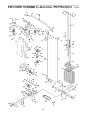
WEEVSY2026.0 R0706A 32 31 33 52 54 63 62 70 70 68 38 35 36 34 35 68 26 39 68 66 71 70 25 71 69 69 54 35 36 38 32 56 77 68 70 34 35 52 68 77 18 67 56 73 73 67 35 34 35 68 70 69 53 42 3 68 69 14 70 35 14 68 53 88 35 34 34 46 36 56 70 51 48 77 55 51 56 70 35 34 68 35 53 68 68 68 70 1 68 47 57 83 58 23 77 41 2 33 10 79 77 80 56 50 71 69 69 87 15 60 11 12 13 16 77 56 17 37 70 57 70 41 59 EXPLODED DRAWING B-Model No.
WEEVSY2026.0 R0706A 32 31 33 52 54 63 62 70 70 68 38 35 36 34 35 68 26 39 68 66 71 70 25 71 69 69 54 35 36 38 32 56 77 68 70 34 35 52 68 77 18 67 56 73 73 67 35 34 35 68 70 69 53 42 3 68 69 14 70 35 14 68 53 88 35 34 34 46 36 56 70 51 48 77 55 51 56 70 35 34 68 35 53 68 68 68 70 1 68 47 57 83 58 23 77 41 2 33 10 79 77 80 56 50 71 69 69 87 15 60 11 12 13 16 77 56 17 37 70 57 70 41 59 EXPLODED DRAWING B-Model No.