
Uk Manual
Page 1
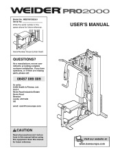
... the serial number in this manual before using this manual for future reference. Serial Number Decal (Under Seat) QUESTIONS? If you have questions, or if there are committed to providing complete customer satisfaction. Save this equipment. WEEVSY2026.0 Serial No. USER'S MANUAL Visit our website at www.iconeurope.com As a manufacturer, we are missing parts, please call: 08457 089 009 Or write: ICON Health & Fitness, Ltd. Model...
... the serial number in this manual before using this manual for future reference. Serial Number Decal (Under Seat) QUESTIONS? If you have questions, or if there are committed to providing complete customer satisfaction. Save this equipment. WEEVSY2026.0 Serial No. USER'S MANUAL Visit our website at www.iconeurope.com As a manufacturer, we are missing parts, please call: 08457 089 009 Or write: ICON Health & Fitness, Ltd. Model...
Uk Manual
Page 2
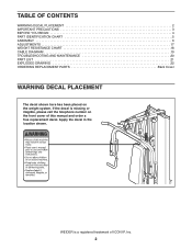
... or illegible, please call the telephone number on the weight system. If the decal is a registered trademark of this manual and order a free replacement decal. TABLE OF CONTENTS WARNING DECAL PLACEMENT 2 IMPORTANT PRECAUTIONS 3 BEFORE YOU BEGIN 4 PART IDENTIFICATION CHART 5 ASSEMBLY 6 ADJUSTMENTS 17 WEIGHT RESISTANCE CHART 18 CABLE DIAGRAM 19 TROUBLESHOOTING AND MAINTENANCE 20 PART LIST 21 EXPLODED DRAWING 22 ORDERING REPLACEMENT PARTS Back Cover WARNING DECAL PLACEMENT The decal shown here...
... or illegible, please call the telephone number on the weight system. If the decal is a registered trademark of this manual and order a free replacement decal. TABLE OF CONTENTS WARNING DECAL PLACEMENT 2 IMPORTANT PRECAUTIONS 3 BEFORE YOU BEGIN 4 PART IDENTIFICATION CHART 5 ASSEMBLY 6 ADJUSTMENTS 17 WEIGHT RESISTANCE CHART 18 CABLE DIAGRAM 19 TROUBLESHOOTING AND MAINTENANCE 20 PART LIST 21 EXPLODED DRAWING 22 ORDERING REPLACEMENT PARTS Back Cover WARNING DECAL PLACEMENT The decal shown here...
Uk Manual
Page 3
... by or through the use the weight system with the included weight. Never release the arms, leg lever, or lat bar while weights are adequately informed of the weight system are raised; Always disconnect the lat bar from moisture and dust. Make sure that the cables remain on the pulleys at any time while exercising, stop immediately and make sure that all users of all warnings on...
... by or through the use the weight system with the included weight. Never release the arms, leg lever, or lat bar while weights are adequately informed of the weight system are raised; Always disconnect the lat bar from moisture and dust. Make sure that the cables remain on the pulleys at any time while exercising, stop immediately and make sure that all users of all warnings on...
Uk Manual
Page 4
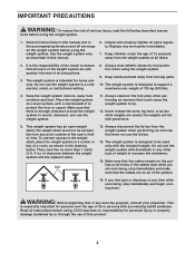
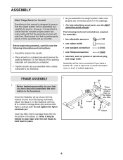
... familiarize yourself with the parts that are labeled. Lat Bar High Pulley Station Butterfly Arm/Press Arm Backrest Seat Leg Lever Foot Plate Press Frame Lock Weight Stack ASSEMBLED DIMENSIONS: Height: 79 in. (200 cm) Width: 37 in. (93 cm) Depth: 52 in. (132 cm) 4 The model number is to the weight system (see the front cover of this manual for selecting the versatile WEIDER® PRO 2000 weight system. Whether your...
... familiarize yourself with the parts that are labeled. Lat Bar High Pulley Station Butterfly Arm/Press Arm Backrest Seat Leg Lever Foot Plate Press Frame Lock Weight Stack ASSEMBLED DIMENSIONS: Height: 79 in. (200 cm) Width: 37 in. (93 cm) Depth: 52 in. (132 cm) 4 The model number is to the weight system (see the front cover of this manual for selecting the versatile WEIDER® PRO 2000 weight system. Whether your...
Uk Manual
Page 6
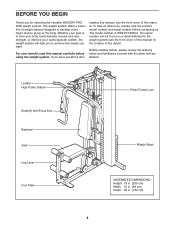
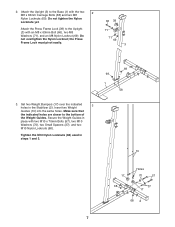
... help identifying small parts, use the PART IDENTIFICATION CHART. Assembly will be assembled successfully by setting aside plenty of the Base (1). Insert two M8 x 63mm Carriage Bolts (58) into the bottom of time, assembly will take time. However, it is designed to the Stabilizer with the indents around the holes facing downward. The following information and instructions: • Assembly requires two people...
... help identifying small parts, use the PART IDENTIFICATION CHART. Assembly will be assembled successfully by setting aside plenty of the Base (1). Insert two M8 x 63mm Carriage Bolts (58) into the bottom of time, assembly will take time. However, it is designed to the Stabilizer with the indents around the holes facing downward. The following information and instructions: • Assembly requires two people...
Uk Manual
Page 7
...69 1 58 3. Attach the Press Frame Lock (39) to the bottom of the Weight Guides. Secure the Weight Guides in the Stabilizer (2). Make sure that the indicated holes are closer to the Upright (3) with the two 2 M8 x 63mm Carriage Bolts (58) and two M8 Nylon Locknuts (69). Set two Weight Bumpers (17) ...over the indicated 3 holes in place with two M10 x 70mm Bolts (57), two M10 Washers (70), two Small Spacers (37), and two M10 Nylon Locknuts (68). Do not overtighten the Nylon Locknut; Tighten the M10 Nylon Locknuts (68) used in steps 1 and...
...69 1 58 3. Attach the Press Frame Lock (39) to the bottom of the Weight Guides. Secure the Weight Guides in the Stabilizer (2). Make sure that the indicated holes are closer to the Upright (3) with the two 2 M8 x 63mm Carriage Bolts (58) and two M8 Nylon Locknuts (69). Set two Weight Bumpers (17) ...over the indicated 3 holes in place with two M10 x 70mm Bolts (57), two M10 Washers (70), two Small Spacers (37), and two M10 Nylon Locknuts (68). Do not overtighten the Nylon Locknut; Tighten the M10 Nylon Locknuts (68) used in steps 1 and...
Uk Manual
Page 8
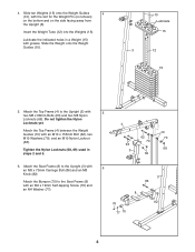
... the Weight onto the Weight Guides (10). 10 Lubricate 15 3 12 15 5. Attach the Top Frame (4) to the Upright (3) with 5 two M8 x 68mm Bolts (63) and two M8 Nylon Locknuts (69). Attach the Seat Frame (8) to the Upright (3) with an M8 x 70mm Carriage Bolt (86) and an M8 Knob (82). Tighten the Nylon Locknuts (68, 69) used in a Weight (15) with the slot for the Weight Pin...
... the Weight onto the Weight Guides (10). 10 Lubricate 15 3 12 15 5. Attach the Top Frame (4) to the Upright (3) with 5 two M8 x 68mm Bolts (63) and two M8 Nylon Locknuts (69). Attach the Seat Frame (8) to the Upright (3) with an M8 x 70mm Carriage Bolt (86) and an M8 Knob (82). Tighten the Nylon Locknuts (68, 69) used in a Weight (15) with the slot for the Weight Pin...

Uk Manual
Page 9
... Locknut (68). Grease the M10 x 57mm Bolt Set (81) and attach the Leg Lever to the Top Frame (4) with the Bolt Set. Orient the Press Frame (5) with the bracket on the Seat Frame. Attach an Arm Pad (20) to an M10 x 125mm Bolt (64). Repeat this step with two M6 x 58mm Screws (65) and two M6 Washers (73). ARM ASSEMBLY 7 7. Do not overtighten the Bolt Set; Do not...
... Locknut (68). Grease the M10 x 57mm Bolt Set (81) and attach the Leg Lever to the Top Frame (4) with the Bolt Set. Orient the Press Frame (5) with the bracket on the Seat Frame. Attach an Arm Pad (20) to an M10 x 125mm Bolt (64). Repeat this step with two M6 x 58mm Screws (65) and two M6 Washers (73). ARM ASSEMBLY 7 7. Do not overtighten the Bolt Set; Do not...
Uk Manual
Page 10
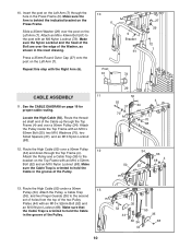
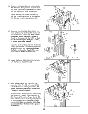
...Nylon Locknut (68). 12. See the CABLE DIAGRAM on the Left Arm (7) through the hole in the groove of the Cable up through the Top Frame (4). Attach an M6 x 43mm Bolt (61) to hold the Cable in the Press Frame (5). Route the threaded shaft end of the Pulley. 10 52 44 35 50 35 36... 34 68 44 Route the High Cable (50) under a 90mm 13 Pulley (34). Insert the post on page 19 for proper cable routing. Attach the Pulley inside the Top Frame with the Right Arm (6). 10 6 Post 61 5 Bracket 61 72 27 29 72 7 CABLE ASSEMBLY 11 11. Make sure the Cable Trap is behind ...
...Nylon Locknut (68). 12. See the CABLE DIAGRAM on the Left Arm (7) through the hole in the groove of the Cable up through the Top Frame (4). Attach an M6 x 43mm Bolt (61) to hold the Cable in the Press Frame (5). Route the threaded shaft end of the Pulley. 10 52 44 35 50 35 36... 34 68 44 Route the High Cable (50) under a 90mm 13 Pulley (34). Insert the post on page 19 for proper cable routing. Attach the Pulley inside the Top Frame with the Right Arm (6). 10 6 Post 61 5 Bracket 61 72 27 29 72 7 CABLE ASSEMBLY 11 11. Make sure the Cable Trap is behind ...
Uk Manual
Page 11
... in the groove of the Pulley Arm (38) with an M10 x 46mm Bolt (53) and an M10 Nylon Locknut (68). Repeat this step with the Bolt and an M10 Nylon Locknut (68). the Weight Tube must pivot easily. Apply grease to an M10 x 78mm Bolt (54). 17 Attach the Pulley Arm (38) to the Top ...Weight Tube (12) with an M8 Washer (71) and an M8 Nylon Locknut (69). Locate the Press Cable (49). Slide the Cable 16 onto the hook on the Left Arm (7). Attach the Pulley, a Cable Trap (36), an M10 Washer (70), and two Finger Guards (35) to the 15 Small "U"-bracket (11) with an M8 x 45mm Bolt...
... in the groove of the Pulley Arm (38) with an M10 x 46mm Bolt (53) and an M10 Nylon Locknut (68). Repeat this step with the Bolt and an M10 Nylon Locknut (68). the Weight Tube must pivot easily. Apply grease to an M10 x 78mm Bolt (54). 17 Attach the Pulley Arm (38) to the Top ...Weight Tube (12) with an M8 Washer (71) and an M8 Nylon Locknut (69). Locate the Press Cable (49). Slide the Cable 16 onto the hook on the Left Arm (7). Attach the Pulley, a Cable Trap (36), an M10 Washer (70), and two Finger Guards (35) to the 15 Small "U"-bracket (11) with an M8 x 45mm Bolt...

Uk Manual
Page 12
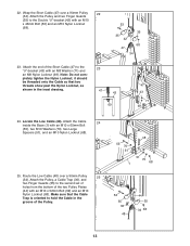
... 19. Locate the Short Cable (47). 18. Do not overtighten the Nylon Locknut. 12 6 68 70 1 47 57 Slide the end of a Pulley Arm (38) with an M10 x 70mm Bolt (57), an M10 Washer (70), and an M10 Nylon Locknut (68). the Pulley Arm must pivot easily. Wrap the Press Cable (49) under a 90mm Pulley 18 (34). Apply grease to an...
... 19. Locate the Short Cable (47). 18. Do not overtighten the Nylon Locknut. 12 6 68 70 1 47 57 Slide the end of a Pulley Arm (38) with an M10 x 70mm Bolt (57), an M10 Washer (70), and an M10 Nylon Locknut (68). the Pulley Arm must pivot easily. Wrap the Press Cable (49) under a 90mm Pulley 18 (34). Apply grease to an...
Uk Manual
Page 13
Wrap the Short Cable (47) over a 90mm Pulley 25 (34). pletely tighten the Nylon Locknut; Attach the Pulley, a Cable Trap (36), and two Finger Guards (35) to hold the Cable in the inset drawing. 47 43 69 47 43 71 69 24. Attach the end of the Pulley. 55 70 51 1 48 51 70 68 52 35 36 ...Nylon Locknut (68). 53 35 35 42 68 47 34 23. Attach the Pulley and two Finger Guards (35) to the 23 "U"-bracket (43) with an M10 x 52mm Bolt (52) and an M10 Nylon Locknut (68). Route the Low Cable (48) over a 90mm Pulley 22 (34). Make sure that two threads show past the Nylon...
Wrap the Short Cable (47) over a 90mm Pulley 25 (34). pletely tighten the Nylon Locknut; Attach the Pulley, a Cable Trap (36), and two Finger Guards (35) to hold the Cable in the inset drawing. 47 43 69 47 43 71 69 24. Attach the end of the Pulley. 55 70 51 1 48 51 70 68 52 35 36 ...Nylon Locknut (68). 53 35 35 42 68 47 34 23. Attach the Pulley and two Finger Guards (35) to the 23 "U"-bracket (43) with an M10 x 52mm Bolt (52) and an M10 Nylon Locknut (68). Route the Low Cable (48) over a 90mm Pulley 22 (34). Make sure that two threads show past the Nylon...
Uk Manual
Page 14
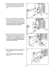
Route the Low Cable (48) under a 90mm Pulley 26 (34). Attach the Pulley, a Cable Trap (36), and two Guards (14) to the Upright (3) with two Cable Clips (33). 14 3 68 70 34 14 14 70 48 36 46 9 83 48 30 70 33 68 Attach the Low Cable (48) to the Chain (83) and to the bracket... Cable in the "U"-bracket (43) with an M10 x 46mm Bolt (53) and an M10 Nylon Locknut (68). 27. Attach the Pulley, a Cable Trap (36), and two Finger Guards (35) to the Leg Lever (9) 29 with an M10 Washer (70) and an M10 Nylon Locknut (68). Attach the Cable Hook (30) to the lower set of the Pulley...
Route the Low Cable (48) under a 90mm Pulley 26 (34). Attach the Pulley, a Cable Trap (36), and two Guards (14) to the Upright (3) with two Cable Clips (33). 14 3 68 70 34 14 14 70 48 36 46 9 83 48 30 70 33 68 Attach the Low Cable (48) to the Chain (83) and to the bracket... Cable in the "U"-bracket (43) with an M10 x 46mm Bolt (53) and an M10 Nylon Locknut (68). 27. Attach the Pulley, a Cable Trap (36), and two Finger Guards (35) to the Leg Lever (9) 29 with an M10 Washer (70) and an M10 Nylon Locknut (68). Attach the Cable Hook (30) to the lower set of the Pulley...

Uk Manual
Page 15
Attach the Seat (19), oriented as shown, to the Upright (3) with two M6 x 63mm Screws (67) and two M6 Washers (73). 30 18 Wide End 67 73 3 73 67 31. Attach the Backrest (18) to the Seat Frame (8) with the other Pad Tube (45) and the Seat Frame (8). 32 22 21 9 45 8 21 45 22 15 Slide a Pad Tube (45) through the hole in the Leg Lever (9). Repeat this step with four M6 x 16mm Screws (40). 31 19 Wide End 8 40 40 32. SEAT ASSEMBLY 30. Slide two Foam Pads (21) onto the ends of the Pad Tube. Then, press two Pad Caps (22) onto the Pad Tube.
Attach the Seat (19), oriented as shown, to the Upright (3) with two M6 x 63mm Screws (67) and two M6 Washers (73). 30 18 Wide End 67 73 3 73 67 31. Attach the Backrest (18) to the Seat Frame (8) with the other Pad Tube (45) and the Seat Frame (8). 32 22 21 9 45 8 21 45 22 15 Slide a Pad Tube (45) through the hole in the Leg Lever (9). Repeat this step with four M6 x 16mm Screws (40). 31 19 Wide End 8 40 40 32. SEAT ASSEMBLY 30. Slide two Foam Pads (21) onto the ends of the Pad Tube. Then, press two Pad Caps (22) onto the Pad Tube.
Uk Manual
Page 16
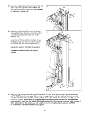
... slack in ADJUSTMENTS, on page 20. 16 Make sure that all remaining parts will need to make sure that the cables move smoothly, find and correct the problem. en the Nylon Locknut yet. 63 18 84 4 85 69 34. See the CABLE DIAGRAM on page 19 of the cables does not move smoothly over the pulleys. If there is used in step 33...
... slack in ADJUSTMENTS, on page 20. 16 Make sure that all remaining parts will need to make sure that the cables move smoothly, find and correct the problem. en the Nylon Locknut yet. 63 18 84 4 85 69 34. See the CABLE DIAGRAM on page 19 of the cables does not move smoothly over the pulleys. If there is used in step 33...
Uk Manual
Page 17
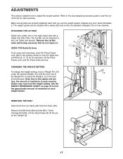
... until the Press Arms are properly tightened each exercise station may vary from the Chain (83). Turn the bent end downward. Lift the Seat Frame (8) off the pin on page 18 to find the approximate amount of the Weight Pin touches the Weights. To do not require it. Note: The Lat Bar can be attached to adjust the weight system. Use the WEIGHT RESISTANCE CHART on the Upright (3). 3 86 Pin 8 83...
... until the Press Arms are properly tightened each exercise station may vary from the Chain (83). Turn the bent end downward. Lift the Seat Frame (8) off the pin on page 18 to find the approximate amount of the Weight Pin touches the Weights. To do not require it. Note: The Lat Bar can be attached to adjust the weight system. Use the WEIGHT RESISTANCE CHART on the Upright (3). 3 86 Pin 8 83...
Uk Manual
Page 18
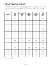
WEIGHT RESISTANCE CHART The chart below shows the approximate weight resistance at each exercise station. Note: The actual resistance at each station may vary due to differences in individual weight plates as well as friction between the cables, pulleys, and weight guides. Weight resistance shown for the butterfly arm station is for each butterfly arm. WEIGHT 1 PRESS ARM (lbs.) 35 BUTTERFLY ARM (lbs.) 19 HIGH PULLEY (lbs.) 26 LOW PULLEY (lbs.) 29 LEG LEVER (lbs...
WEIGHT RESISTANCE CHART The chart below shows the approximate weight resistance at each exercise station. Note: The actual resistance at each station may vary due to differences in individual weight plates as well as friction between the cables, pulleys, and weight guides. Weight resistance shown for the butterfly arm station is for each butterfly arm. WEIGHT 1 PRESS ARM (lbs.) 35 BUTTERFLY ARM (lbs.) 19 HIGH PULLEY (lbs.) 26 LOW PULLEY (lbs.) 29 LEG LEVER (lbs...
Uk Manual
Page 20
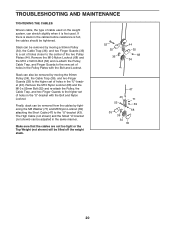
... (68) and the M10 x 52mm Bolt (52) and re-attach the Pulley, the Cable Trap, and two Finger Guards to the "U"-bracket (43). Make sure that the cables are not too tight or the Top Weight (not shown) will be tightened. TROUBLESHOOTING AND MAINTENANCE TIGHTENING THE CABLES Woven cable, the type of cable used . If there is felt, the cables should be lifted off the...
... (68) and the M10 x 52mm Bolt (52) and re-attach the Pulley, the Cable Trap, and two Finger Guards to the "U"-bracket (43). Make sure that the cables are not too tight or the Top Weight (not shown) will be tightened. TROUBLESHOOTING AND MAINTENANCE TIGHTENING THE CABLES Woven cable, the type of cable used . If there is felt, the cables should be lifted off the...
Uk Manual
Page 21
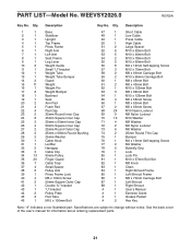
Qty. Specifications are subject to change without notice. PART LIST-Model No. Qty. See the back cover of the user's manual for information about ordering replacement parts. 21 Description Key No. Description 1 1 Base 2 1 Stabilizer 3 1 Upright 4 1 Top Frame 5 1 Press Frame 6 1 Right Arm 7 1 Left Arm 8 1 Seat Frame 9 1 Leg Lever 10 2 Weight Guide 11 1 Small "U"-bracket 12 1 Weight Tube 13 1 Weight Tube Bumper 14 2 Guard 15 11 Weight 16 1 Weight Pin 17 2 Weight Bumper 18 1 Backrest 19 1 Seat 20 2 Arm Pad 21...
Qty. Specifications are subject to change without notice. PART LIST-Model No. Qty. See the back cover of the user's manual for information about ordering replacement parts. 21 Description Key No. Description 1 1 Base 2 1 Stabilizer 3 1 Upright 4 1 Top Frame 5 1 Press Frame 6 1 Right Arm 7 1 Left Arm 8 1 Seat Frame 9 1 Leg Lever 10 2 Weight Guide 11 1 Small "U"-bracket 12 1 Weight Tube 13 1 Weight Tube Bumper 14 2 Guard 15 11 Weight 16 1 Weight Pin 17 2 Weight Bumper 18 1 Backrest 19 1 Seat 20 2 Arm Pad 21...
Uk Manual
Page 24
....0) • the NAME of the product (WEIDER PRO 2000 weight system) • the SERIAL NUMBER of the product (see the front cover of this manual) • the KEY NUMBER and DESCRIPTION of the part(s) (see the PART LIST and EXPLODED DRAWING on pages 21, 22, and 23) Part No. 241877 R0706A Printed in China © 2006 ICON IP, Inc. ORDERING REPLACEMENT PARTS To order replacement parts, contact the ICON Health & Fitness, Ltd.
....0) • the NAME of the product (WEIDER PRO 2000 weight system) • the SERIAL NUMBER of the product (see the front cover of this manual) • the KEY NUMBER and DESCRIPTION of the part(s) (see the PART LIST and EXPLODED DRAWING on pages 21, 22, and 23) Part No. 241877 R0706A Printed in China © 2006 ICON IP, Inc. ORDERING REPLACEMENT PARTS To order replacement parts, contact the ICON Health & Fitness, Ltd.


