
English Manual
Page 1
...: ICON Fitness Lifestyle Ltd. O Serial Number Decal QUESTIONS? Model No. Greenwich House 223 North Street Sheepscar Leeds LS7 2AA CAUTION Read all precautions and instructions in this manual before using this manual for future reference. /./z_ io 7 0 0 0 C a al o' 0' o' USER'S MANUAL Save this equipment. WESY50200 Serial No. As a manufacturer, we are missing or damaged parts, we will guarantee you complete satisfaction through our Customer Service...
...: ICON Fitness Lifestyle Ltd. O Serial Number Decal QUESTIONS? Model No. Greenwich House 223 North Street Sheepscar Leeds LS7 2AA CAUTION Read all precautions and instructions in this manual before using this manual for future reference. /./z_ io 7 0 0 0 C a al o' 0' o' USER'S MANUAL Save this equipment. WESY50200 Serial No. As a manufacturer, we are missing or damaged parts, we will guarantee you complete satisfaction through our Customer Service...
English Manual
Page 2
... the press arm, leg lever, lat bar, or nylon strap whilst weights are exercising, stop immediately and begin cooling down. 4. Always disconnect the lat bar from the home gym system at any time whilst exercising, stop immediately and make sure that all users of the home gym system are on a level surface. Replace any exercise program, consult your physician. WARNING: Before beginning this manual. Always secure the leg lever with the long locking pin...
... the press arm, leg lever, lat bar, or nylon strap whilst weights are exercising, stop immediately and begin cooling down. 4. Always disconnect the lat bar from the home gym system at any time whilst exercising, stop immediately and make sure that all users of the home gym system are on a level surface. Replace any exercise program, consult your physician. WARNING: Before beginning this manual. Always secure the leg lever with the long locking pin...
English Manual
Page 3
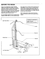
... parts that are labelled. High Pulley Station O ASSEMBLED DIMENSIONS: Height: 78 inches Base: 35 inches x 86 inches Lat Bar Weight Stack Press Arm Backrest O Low Pulley Station 0` o' o' Foot Plates Leg Lever If you for selecting the versatile WEIDER. BEFORE YOU BEGIN Thank you have additional ques- The COBRA 1000 offers a selection of weight stations designed to achieve the specific results you , please note the product model and serial number...
... parts that are labelled. High Pulley Station O ASSEMBLED DIMENSIONS: Height: 78 inches Base: 35 inches x 86 inches Lat Bar Weight Stack Press Arm Backrest O Low Pulley Station 0` o' o' Foot Plates Leg Lever If you for selecting the versatile WEIDER. BEFORE YOU BEGIN Thank you have additional ques- The COBRA 1000 offers a selection of weight stations designed to achieve the specific results you , please note the product model and serial number...
English Manual
Page 4
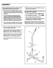
... you assemble the COBRA 1000, be sure that all parts are oriented as shown in the drawings. • Tighten all parts as grease or petroleum jelly, and soapy water will be needed. ASSEMBLY Before beginning assembly, carefully read the following tools: A socket set, a set of open-end or closed-end wrenches, or a set of this manual. Assembly will also be more convenient if you assemble them, unless instructed...
... you assemble the COBRA 1000, be sure that all parts are oriented as shown in the drawings. • Tighten all parts as grease or petroleum jelly, and soapy water will be needed. ASSEMBLY Before beginning assembly, carefully read the following tools: A socket set, a set of open-end or closed-end wrenches, or a set of this manual. Assembly will also be more convenient if you assemble them, unless instructed...
English Manual
Page 5
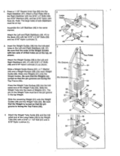
... of the Long Cable (18) to the Base (45) with 5/16" x 2" Bolts (48) and 5/16" Nylon Locknuts (1) as shown. Press a 1 1/2" Square Inner Cap (50) into the indicated holes in the Left and Right Stabilisers (46, 47). The pin on top. Attach the Weight Tube Guide (55) and the indicated end of the Weight Guides with a 5/16" x 1 1/2" Bolt (21) and a 5/16...
... of the Long Cable (18) to the Base (45) with 5/16" x 2" Bolts (48) and 5/16" Nylon Locknuts (1) as shown. Press a 1 1/2" Square Inner Cap (50) into the indicated holes in the Left and Right Stabilisers (46, 47). The pin on top. Attach the Weight Tube Guide (55) and the indicated end of the Weight Guides with a 5/16" x 1 1/2" Bolt (21) and a 5/16...
English Manual
Page 6
... ends of the Pulley Brackets must be on top. Attach the Pulley to the Weight 5 Guides (38) with a 3/8" x 1 3/4" Bolt (22) and a 3/8" Nylon Locknut (2). 8. Align the holes in the Press Arm with soapy water. Insert the Short "L"Pin (14) into the Press Arm Lever (8). Wet the handles on the Indicated side of the Press Arm Lever (8). Attach the Pulley to the Press Arm Lever (8) with the 3/8" x 2 3/4" Bolt (12), two...
... ends of the Pulley Brackets must be on top. Attach the Pulley to the Weight 5 Guides (38) with a 3/8" x 1 3/4" Bolt (22) and a 3/8" Nylon Locknut (2). 8. Align the holes in the Press Arm with soapy water. Insert the Short "L"Pin (14) into the Press Arm Lever (8). Wet the handles on the Indicated side of the Press Arm Lever (8). Attach the Pulley to the Press Arm Lever (8) with the 3/8" x 2 3/4" Bolt (12), two...

English Manual
Page 7
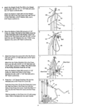
Wrap the Long Cable (18) around a 3 1/2" Pulley (4). Attach the Pulley to the Front Leg (31) with a 3/8" x 4" Bolt (17) and a 3/8" Nylon Locknut (2). Be sure that the Short Lock Pin is turned so that the clip on the Base (45) with two 5/16" x 2 1/2" Bolts (41), two 5/16" Washers (20), and two 5/16" Nylon Jam Nuts (5). Attach the Pulley and the Cable Trap (16) to 10...
Wrap the Long Cable (18) around a 3 1/2" Pulley (4). Attach the Pulley to the Front Leg (31) with a 3/8" x 4" Bolt (17) and a 3/8" Nylon Locknut (2). Be sure that the Short Lock Pin is turned so that the clip on the Base (45) with two 5/16" x 2 1/2" Bolts (41), two 5/16" Washers (20), and two 5/16" Nylon Jam Nuts (5). Attach the Pulley and the Cable Trap (16) to 10...
English Manual
Page 8
... Backrest (27) with the #8 x 3/4" Self-tapping Screw (66). 14. The long end of the Long Cable (18) with a 5/16" x 3" Bolt (69) and a 5/16" Nylon Locknut (1). Attach the Leg Lever Bumper (65) to the Leg Lever (37) with two 1/4" x 1/2" Screws (25). 28 Attach the other Backrest Bracket (26) to the Leg Lever with a 5/16" x 1 1/2" Bolt (21) and a 5/16" Nylon Locknut (1). Insert...
... Backrest (27) with the #8 x 3/4" Self-tapping Screw (66). 14. The long end of the Long Cable (18) with a 5/16" x 3" Bolt (69) and a 5/16" Nylon Locknut (1). Attach the Leg Lever Bumper (65) to the Leg Lever (37) with two 1/4" x 1/2" Screws (25). 28 Attach the other Backrest Bracket (26) to the Leg Lever with a 5/16" x 1 1/2" Bolt (21) and a 5/16" Nylon Locknut (1). Insert...
English Manual
Page 9
... not legible, please call our Customer Service Department to order a free replacement decal (see ORDERING REPLACEMENT PARTS on your home gym system. ATTENTION Enfoncez toujours la goupille de verrouillage quand vous vous servez du bras de presse. AWERTENZA Inserire sempre le perne di sicurezza durante I • Rimuovere Ia Lat Bar quando non in use el brazo de presidn del banco. WAARSCHUWING...
... not legible, please call our Customer Service Department to order a free replacement decal (see ORDERING REPLACEMENT PARTS on your home gym system. ATTENTION Enfoncez toujours la goupille de verrouillage quand vous vous servez du bras de presse. AWERTENZA Inserire sempre le perne di sicurezza durante I • Rimuovere Ia Lat Bar quando non in use el brazo de presidn del banco. WAARSCHUWING...
English Manual
Page 10
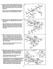
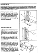
... the Weights, and turn the Pin so that the handles are in the correct starting position for safekeeping. Lift the Backrest Frame off the Base. 67 28 45 37 18 n Note: Due to the cables and pulleys, the actual amount of resistance at each part of the home gym system can be reduced. For some exercises, you will need to remove the Press Arm (7). Reinsert...
... the Weights, and turn the Pin so that the handles are in the correct starting position for safekeeping. Lift the Backrest Frame off the Base. 67 28 45 37 18 n Note: Due to the cables and pulleys, the actual amount of resistance at each part of the home gym system can be reduced. For some exercises, you will need to remove the Press Arm (7). Reinsert...
English Manual
Page 11
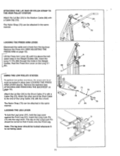
Remove the Press Arm (SEE ADJUSTING THE PRESS ARM on e 10). Remove the backrest (see LOCKING THE PRESS ARM LEVER above the indi- Attach the Lat Bar (24) to the Short Cable (71) with the s-hook. Insert the Long "L"-Pin (58) through the holes in the Weight Guides (38). cated holes in the Weight Guides. in. 58 O 38 USING THE LOW PULLEY STATION \ Tr• perform low pu!!ey excrolcoo., tho...
Remove the Press Arm (SEE ADJUSTING THE PRESS ARM on e 10). Remove the backrest (see LOCKING THE PRESS ARM LEVER above the indi- Attach the Lat Bar (24) to the Short Cable (71) with the s-hook. Insert the Long "L"-Pin (58) through the holes in the Weight Guides (38). cated holes in the Weight Guides. in. 58 O 38 USING THE LOW PULLEY STATION \ Tr• perform low pu!!ey excrolcoo., tho...
English Manual
Page 12
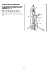
Secure the Cable with the Cable. Clip (72). 38 8 a 71 72 27 28 FOLDING THE BACKREST FOR STORAGE First, lock the Press Arm Lever (8) in place at the top of the Weight Guides. Lift the Backrest (27) up and lean it against the Weight Guides (38). Wrap the Short Cable (71) around the Backrest Frame (28) and one of the Weight Guides (see LOCKING THE PRESS ARM LEVER on page 11).
Secure the Cable with the Cable. Clip (72). 38 8 a 71 72 27 28 FOLDING THE BACKREST FOR STORAGE First, lock the Press Arm Lever (8) in place at the top of the Weight Guides. Lift the Backrest (27) up and lean it against the Weight Guides (38). Wrap the Short Cable (71) around the Backrest Frame (28) and one of the Weight Guides (see LOCKING THE PRESS ARM LEVER on page 11).
English Manual
Page 13
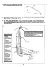
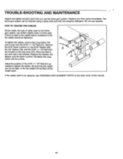
... home gym system. To tighten the cables, remove the Long Cable (18) and s-hook from the bracket on the Leg Lever (37). Re-attach the Long Cable with the s-hook. 0 21 18 1'I 19 20 43 37 Adjust the position of cable used . If the cables need to be replaced, see ORDERING REPLACEMENT PARTS on the home gym system, can be lifted off the weight stack. TROUBLE-SHOOTING AND MAINTENANCE Inspect and tighten all parts...
... home gym system. To tighten the cables, remove the Long Cable (18) and s-hook from the bracket on the Leg Lever (37). Re-attach the Long Cable with the s-hook. 0 21 18 1'I 19 20 43 37 Adjust the position of cable used . If the cables need to be replaced, see ORDERING REPLACEMENT PARTS on the home gym system, can be lifted off the weight stack. TROUBLE-SHOOTING AND MAINTENANCE Inspect and tighten all parts...
English Manual
Page 14
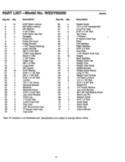
... Nut Handgrip Press Arm Press Arm Lever Pulley Bracket 1 1/2" Square Bushing Long Lock Pin 3/8" x 2 3/4" Bolt 17/32" Long Spacer Short "L"-Pin 4 1/2" Pulley Cable Trap 3/8" x 4" Bolt Long Cable 3/4" Spacer 5/16" Washer 5/16" x 1 1/2" Bolt 3/8" x 1 3/4" Bolt 5/16" x 2 1/4" Bolt Lat Bar 1/4" x 1/2" Screw Backrest Bracket Backrest Backrest Frame 5/16" x 2 3/4" Bolt Leg Lever Bracket Front Leg 7" Foam Pad 5 3/4" Foam Pad Pad Tube 3/4" Round Inner Cap 2" Square Inner Cap Leg Lever Key No. Specifications are subject to change without notice. PART LIST Model No. WESY50200...
... Nut Handgrip Press Arm Press Arm Lever Pulley Bracket 1 1/2" Square Bushing Long Lock Pin 3/8" x 2 3/4" Bolt 17/32" Long Spacer Short "L"-Pin 4 1/2" Pulley Cable Trap 3/8" x 4" Bolt Long Cable 3/4" Spacer 5/16" Washer 5/16" x 1 1/2" Bolt 3/8" x 1 3/4" Bolt 5/16" x 2 1/4" Bolt Lat Bar 1/4" x 1/2" Screw Backrest Bracket Backrest Backrest Frame 5/16" x 2 3/4" Bolt Leg Lever Bracket Front Leg 7" Foam Pad 5 3/4" Foam Pad Pad Tube 3/4" Round Inner Cap 2" Square Inner Cap Leg Lever Key No. Specifications are subject to change without notice. PART LIST Model No. WESY50200...
English Manual
Page 15
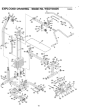
EXPLODED DRAWING Model No. WESY50200 j 36 6 ( 1t 24 R0896A 13 68 Cb-72 12 4 d1 20 42 '6( 53 • 68 •, 62 6 8 1 55 61 14 8 4 69 71 2 9 23-°"' 22 9 10 15 7 27 70 c\ 6 21 20 41 54 39 38
EXPLODED DRAWING Model No. WESY50200 j 36 6 ( 1t 24 R0896A 13 68 Cb-72 12 4 d1 20 42 '6( 53 • 68 •, 62 6 8 1 55 61 14 8 4 69 71 2 9 23-°"' 22 9 10 15 7 27 70 c\ 6 21 20 41 54 39 38
English Manual
Page 16
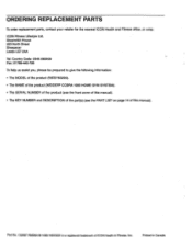
... information: • The MODEL of the product (WESY50200). • The NAME of the product (WEIDER® COBRA 1000 HOME GYM SYSTEM). • The SERIAL NUMBER of the product (see the front cover of this manual). • The KEY NUMBER and DESCRIPTION of the part(s) (see the PART LIST on page 14 of ICON Health & Fitness, Inc. ORDERING REPLACEMENT PARTS To order replacement parts, contact your retailer for the nearest ICON Health and Fitness office, or write: ICON Fitness...
... information: • The MODEL of the product (WESY50200). • The NAME of the product (WEIDER® COBRA 1000 HOME GYM SYSTEM). • The SERIAL NUMBER of the product (see the front cover of this manual). • The KEY NUMBER and DESCRIPTION of the part(s) (see the PART LIST on page 14 of ICON Health & Fitness, Inc. ORDERING REPLACEMENT PARTS To order replacement parts, contact your retailer for the nearest ICON Health and Fitness office, or write: ICON Fitness...
English Manual
Page 17
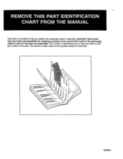
Important: Some parts may have been pre-assembled for assembly. R0896A If you identify the small parts used in assembly. The number in the parts bags, check to see if it has been pre-assembled. REMOVE THIS PART IDENTIFICATION CHART FROM THE MANUAL This chart is provided to help you cannot find a part in parenthesis below each part refers to the key number of the part. The second number refers to the quantity needed for shipping purposes.
Important: Some parts may have been pre-assembled for assembly. R0896A If you identify the small parts used in assembly. The number in the parts bags, check to see if it has been pre-assembled. REMOVE THIS PART IDENTIFICATION CHART FROM THE MANUAL This chart is provided to help you cannot find a part in parenthesis below each part refers to the key number of the part. The second number refers to the quantity needed for shipping purposes.

English Manual
Page 19
\\\\\\\\\\ 5/16" x 2 3/4" Bolt (29)-6 5/16" x 3" Bolt (69)-2 5/16" x 3 3/4" Bolt (62)-1 \\\\\\ 3/8" x 4" Bolt (17)-1 0 3/4" Spacer (19)-1 0 17/32" Long Spacer (13)-2 3/4" Round Inner Cap (35)-6 Leg Bumper (65)-1 1 1/2" Square Bushing (10)-1 Weight Pin (63)-1
\\\\\\\\\\ 5/16" x 2 3/4" Bolt (29)-6 5/16" x 3" Bolt (69)-2 5/16" x 3 3/4" Bolt (62)-1 \\\\\\ 3/8" x 4" Bolt (17)-1 0 3/4" Spacer (19)-1 0 17/32" Long Spacer (13)-2 3/4" Round Inner Cap (35)-6 Leg Bumper (65)-1 1 1/2" Square Bushing (10)-1 Weight Pin (63)-1


