Operating Instructions
Page 3
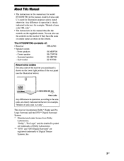
You can also use the controls on the receiver if they have the same or similar names as those on the supplied remote. Center speaker SS-CNP700 - Sub woofer SS-WP700 About area codes The area code of the receiver you purchased is shown on the lower right portion ...; Receiver STR-K700 • Speaker system - The HT-DDW700 consists of area code CEL only". • The instructions in the text, for model HT-DDW700. In this manual are registered trademarks of area code AA only". Any difference in operation is clearly indicated in this manual describe the controls on the remote....
You can also use the controls on the receiver if they have the same or similar names as those on the supplied remote. Center speaker SS-CNP700 - Sub woofer SS-WP700 About area codes The area code of the receiver you purchased is shown on the lower right portion ...; Receiver STR-K700 • Speaker system - The HT-DDW700 consists of area code CEL only". • The instructions in the text, for model HT-DDW700. In this manual are registered trademarks of area code AA only". Any difference in operation is clearly indicated in this manual describe the controls on the remote....
Operating Instructions
Page 9
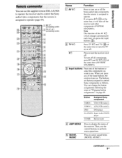
... operate the receiver and to control the Sony audio/video components that the remote is assigned to turn the receiver on /standby) switch TUNER AMPMENU 23 4 (A:t MOVIE MUSIC ) DUALMONO ° C2D ° C.0 FMMODE 21 CAD ° •°(-7 °) ° ' >10/. 20! 0/10 CLEAR D.SKIP 8 DISPLAY TO 19 18 0 RETURNIEXIT PTRVF,SE-T- Press to control Sony components...
... operate the receiver and to control the Sony audio/video components that the remote is assigned to turn the receiver on /standby) switch TUNER AMPMENU 23 4 (A:t MOVIE MUSIC ) DUALMONO ° C2D ° C.0 FMMODE 21 CAD ° •°(-7 °) ° ' >10/. 20! 0/10 CLEAR D.SKIP 8 DISPLAY TO 19 18 0 RETURNIEXIT PTRVF,SE-T- Press to control Sony components...
Operating Instructions
Page 17
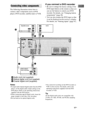
... you can be displayed on the receiver's display. For details, see "Changing button assignments" (page 49). • You can also rename the DVD input so that you connect a DVD recorder • Be sure to change the factory setting of the DVD input button on the remote so that it DVD player/ DVD... setting on the DVD player. it can use the button to the operating instructions supplied with the DVD recorder or VCR. For details, refer to control your DVD recorder. Tip All the digital audio jacks are compatible with 32 kHz, 44.1 kHz, 48 kHz, and 96 kHz sampling frequencies. 17us ...
... you can be displayed on the receiver's display. For details, see "Changing button assignments" (page 49). • You can also rename the DVD input so that you connect a DVD recorder • Be sure to change the factory setting of the DVD input button on the remote so that it DVD player/ DVD... setting on the DVD player. it can use the button to the operating instructions supplied with the DVD recorder or VCR. For details, refer to control your DVD recorder. Tip All the digital audio jacks are compatible with 32 kHz, 44.1 kHz, 48 kHz, and 96 kHz sampling frequencies. 17us ...
Operating Instructions
Page 47
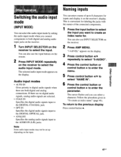
... digital and analog audio input jacks on the receiver. 1 Turn INPUT SELECTOR on the input. The selected audio input mode appears on the receiver to select "NAME IN". 6 Press the control button or control button . Audio input modes • AUTO IN...receiver. 2 Press AMP MENU. uoReaado Jel41O INNIIIIIINIMMIIIIIIIIIIIIIIIIIIIMINIIIIIIIIIIIIIIIIIMIIIIIIM Switching the audio input mode (INPUT MODE) You can select the audio input mode by setting the audio input mode when you connect components to both digital and analog connections. You can also use the input buttons on the remote...
... digital and analog audio input jacks on the receiver. 1 Turn INPUT SELECTOR on the input. The selected audio input mode appears on the receiver to select "NAME IN". 6 Press the control button or control button . Audio input modes • AUTO IN...receiver. 2 Press AMP MENU. uoReaado Jel41O INNIIIIIINIMMIIIIIIIIIIIIIIIIIIIMINIIIIIIIIIIIIIIIIIMIIIIIIM Switching the audio input mode (INPUT MODE) You can select the audio input mode by setting the audio input mode when you connect components to both digital and analog connections. You can also use the input buttons on the remote...
Operating Instructions
Page 49
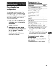
...button for the category you want to control the DVD recorder. For example, if you connect a DVD recorder to the DVD jacks on the receiver, you can set the DVD button on this receiver) 8 DVR (Digital CATV terminal) 9 DSS (Digital Satellite Receiver) 0/10 °Sony VCRs are operated with a VTR 2... the components in your system. For details, refer to its factory settings. at the same time. The remote is reset to the operating instructions supplied with the DVD recorders. To clear all remote button assignments Press l/()I , AUTO CAL and MASTER VOL - eicstueu eq BuIsn 49us
...button for the category you want to control the DVD recorder. For example, if you connect a DVD recorder to the DVD jacks on the receiver, you can set the DVD button on this receiver) 8 DVR (Digital CATV terminal) 9 DSS (Digital Satellite Receiver) 0/10 °Sony VCRs are operated with a VTR 2... the components in your system. For details, refer to its factory settings. at the same time. The remote is reset to the operating instructions supplied with the DVD recorders. To clear all remote button assignments Press l/()I , AUTO CAL and MASTER VOL - eicstueu eq BuIsn 49us
Operating Instructions
Page 54
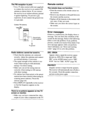
... are weak. • Make sure you select the correct input on the display. DEC. Remote control The remote does not function. • Point the remote at the remote sensor on the receiver. • Remove any problem persists, consult your video component to the TV. DTS-CD)...receiver to "DEC. The FM reception is input and "DEC. Outdoor FM antenna Receiver Ground wire (not supplied) To ground Radio stations cannot be tuned in AM stations with direct tuning). • No stations have been preset or the preset stations have connected the video output of your nearest Sony...
... are weak. • Make sure you select the correct input on the display. DEC. Remote control The remote does not function. • Point the remote at the remote sensor on the receiver. • Remove any problem persists, consult your video component to the TV. DTS-CD)...receiver to "DEC. The FM reception is input and "DEC. Outdoor FM antenna Receiver Ground wire (not supplied) To ground Radio stations cannot be tuned in AM stations with direct tuning). • No stations have been preset or the preset stations have connected the video output of your nearest Sony...
Service Manual
Page 7
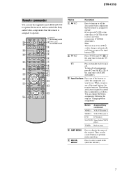
STR-K700 Remote commander You can change the button assignments following the steps in tuner D AMP MENU E MOVIE, MUSIC Press to display the menu of the AV ?/1 switch changes automatically each time you press the input buttons (C). MOVIE MUSIC 1 AV ?/1 (on/standby) switch 2 TV ?/1, ?/1 (on or off the Sony audio/video components that the remote... TV VOL MASTER VOL g f 8 9 q; You can use the supplied remote RM-AAU006 to operate the receiver and to control the Sony audio/video components that the remote is assigned to turn off . ?/1 Press to operate. qa qs qd RETURN...
STR-K700 Remote commander You can change the button assignments following the steps in tuner D AMP MENU E MOVIE, MUSIC Press to display the menu of the AV ?/1 switch changes automatically each time you press the input buttons (C). MOVIE MUSIC 1 AV ?/1 (on/standby) switch 2 TV ?/1, ?/1 (on or off the Sony audio/video components that the remote... TV VOL MASTER VOL g f 8 9 q; You can use the supplied remote RM-AAU006 to operate the receiver and to control the Sony audio/video components that the remote is assigned to turn off . ?/1 Press to operate. qa qs qd RETURN...
Service Manual
Page 13
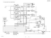
...• R-CH is omitted due to same as L-CH. L • Signal Path : FM A MAIN SECTION SL (Page 12) C FL101 FLUORESCENT INDICATOR TUBE SBL F1 F2 14 29 ... AMP +B Q860-862 +B SWITCH +3.3V +2.5V +5V IC1901 2 +3.3V REG 4 5 +2.5V REG IC1031 3 +5V REG 1 D804-807 T901 IC102 REMOTE 1 CONTROL RECEIVER IC850(1/2) IC850(2/2) 2 15 7 POWER AMP -B Q851,852 -B SWITCH D811 +B -B AUDIO +5V FL101 -20V Q801 -20V REG IC1001 3 +5V REG ... REG 1 R803 D920-923 F1 F2 D910-913 T902 D914 Q901 RELAY DRIVE D915 RY901 STR-K700 13 13 STR-K700 AC IN 3-2. BLOCK DIAGRAM -
...• R-CH is omitted due to same as L-CH. L • Signal Path : FM A MAIN SECTION SL (Page 12) C FL101 FLUORESCENT INDICATOR TUBE SBL F1 F2 14 29 ... AMP +B Q860-862 +B SWITCH +3.3V +2.5V +5V IC1901 2 +3.3V REG 4 5 +2.5V REG IC1031 3 +5V REG 1 D804-807 T901 IC102 REMOTE 1 CONTROL RECEIVER IC850(1/2) IC850(2/2) 2 15 7 POWER AMP -B Q851,852 -B SWITCH D811 +B -B AUDIO +5V FL101 -20V Q801 -20V REG IC1001 3 +5V REG ... REG 1 R803 D920-923 F1 F2 D910-913 T902 D914 Q901 RELAY DRIVE D915 RY901 STR-K700 13 13 STR-K700 AC IN 3-2. BLOCK DIAGRAM -
Service Manual
Page 32
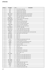
...control signal output (Not used) O Video select control signal output (Not used) O Video select control signal output (Not used) O Video select control signal output (Not used - Not used ) - Power supply (+3.3V) - Not used - STR-K700...(A) VOL_ENC (B) FRONT_RY C/SB_RY REAR_RY NOT_USED NOT_USED NOT_USED NOT_USED DO SLATCH TUNED STEREO RSTX MUTE X1A X0A VSS X0 X1 VCC3 NOT_USED SW1 SW2 SW3 SW4 ... I Data signal input from the remote control sensor I Headphone signal input I Power switch key detect signal input O ADCC DSP input O Power relay control signal output O FL driver signal ...
...control signal output (Not used) O Video select control signal output (Not used) O Video select control signal output (Not used) O Video select control signal output (Not used - Not used ) - Power supply (+3.3V) - Not used - STR-K700...(A) VOL_ENC (B) FRONT_RY C/SB_RY REAR_RY NOT_USED NOT_USED NOT_USED NOT_USED DO SLATCH TUNED STEREO RSTX MUTE X1A X0A VSS X0 X1 VCC3 NOT_USED SW1 SW2 SW3 SW4 ... I Data signal input from the remote control sensor I Headphone signal input I Power switch key detect signal input O ADCC DSP input O Power relay control signal output O FL driver signal ...


