Operating Instructions
Page 4
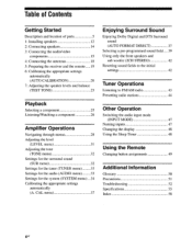
...pre-programmed sound field 39 Using only the front speakers and sub woofer (2CH STEREO) 42 Resetting sound fields to the initial settings 42 Tuner Operations Listening to FM/AM radio 43 Presetting radio stations 44 Other Operation Switching the audio input mode (... 5 1: Installing speakers 12 2: Connecting speakers 14 3: Connecting the audio/video components 15 4: Connecting the antennas 18 5: Preparing the receiver and the remote 19 6: Calibrating the appropriate settings automatically (AUTO CALIBRATION) 20 7: Adjusting the speaker levels and balance (TEST TONE) ...
...pre-programmed sound field 39 Using only the front speakers and sub woofer (2CH STEREO) 42 Resetting sound fields to the initial settings 42 Tuner Operations Listening to FM/AM radio 43 Presetting radio stations 44 Other Operation Switching the audio input mode (... 5 1: Installing speakers 12 2: Connecting speakers 14 3: Connecting the audio/video components 15 4: Connecting the antennas 18 5: Preparing the receiver and the remote 19 6: Calibrating the appropriate settings automatically (AUTO CALIBRATION) 20 7: Adjusting the speaker levels and balance (TEST TONE) ...
Operating Instructions
Page 19
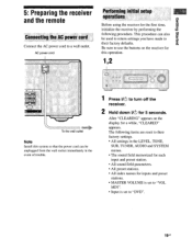
...• All preset stations. • All index names for the first time, initialize the receiver by performing the following items are reset to their factory defaults. papeis Bugle° 5: Preparing the receiver and the remote Connecting the AC power cord Connect the AC power cord to "DVD". 19us... Be sure to turn off the receiver. 2 Hold down IM) for a while, "CLEARED" appears. ...
...• All preset stations. • All index names for the first time, initialize the receiver by performing the following items are reset to their factory defaults. papeis Bugle° 5: Preparing the receiver and the remote Connecting the AC power cord Connect the AC power cord to "DVD". 19us... Be sure to turn off the receiver. 2 Hold down IM) for a while, "CLEARED" appears. ...
Operating Instructions
Page 42
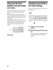
... on the display and all sound fields are reset to their initial setting. 42us "S.F. TIMER AMP MENU 2CH - Using only the front speakers and sub woofer (2CH STEREO) In this operation. 1,2 2 1 Press l/(!) to turn off the receiver. 2 While holding down 2CH, press l/(1). When standard 2 channel stereo sources are downmixed to 2 channel with bass frequencies...
... on the display and all sound fields are reset to their initial setting. 42us "S.F. TIMER AMP MENU 2CH - Using only the front speakers and sub woofer (2CH STEREO) In this operation. 1,2 2 1 Press l/(!) to turn off the receiver. 2 While holding down 2CH, press l/(1). When standard 2 channel stereo sources are downmixed to 2 channel with bass frequencies...
Operating Instructions
Page 49
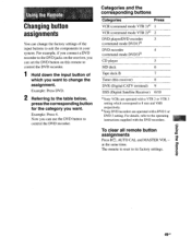
...49us Now you want to change the factory settings of which correspond to the DVD jacks on this receiver) 8 DVR (Digital CATV terminal) 9 DSS (Digital Satellite Receiver) 0/10 °Sony VCRs are operated with a DVD 1 or DVD 3 setting. To clear all remote button assignments...Sony DVD recorders are operated with the DVD recorders. Using the Re e Changing button assignments You can change the assignment. Example: Press DVD. 2 Referring to the table below, press the corresponding button for the category you can use the DVD button to its factory settings. The remote is reset...
...49us Now you want to change the factory settings of which correspond to the DVD jacks on this receiver) 8 DVR (Digital CATV terminal) 9 DSS (Digital Satellite Receiver) 0/10 °Sony VCRs are operated with a DVD 1 or DVD 3 setting. To clear all remote button assignments...Sony DVD recorders are operated with the DVD recorders. Using the Re e Changing button assignments You can change the assignment. Example: Press DVD. 2 Referring to the table below, press the corresponding button for the category you can use the DVD button to its factory settings. The remote is reset...
Operating Instructions
Page 55
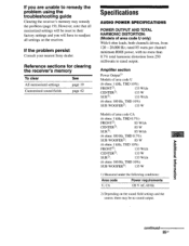
...1) Measured under the following conditions: Area code Power requirements U, CA 120 V AC, 60 Hz 2) Depending on the receiver. If the problem persist Consult your nearest Sony dealer. If you will have to readjust all memorized settings will be no more than 0.7% total harmonic distortion from 120 -...) With 6 ohm loads, both channels driven, from 250 milliwatts to remedy the problem using the troubleshooting guide Clearing the receiver's memory may be reset to their factory settings and you are unable to rated output. However, note that all settings on the sound field settings...
...1) Measured under the following conditions: Area code Power requirements U, CA 120 V AC, 60 Hz 2) Depending on the receiver. If the problem persist Consult your nearest Sony dealer. If you will have to readjust all memorized settings will be no more than 0.7% total harmonic distortion from 120 -...) With 6 ohm loads, both channels driven, from 250 milliwatts to remedy the problem using the troubleshooting guide Clearing the receiver's memory may be reset to their factory settings and you are unable to rated output. However, note that all settings on the sound field settings...
Operating Instructions
Page 56
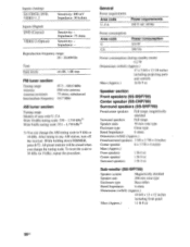
....0 MHz FM wire antenna 75 ohms, unbalanced 10.7 MHz AM tuner section Tuning range Models of area code U, CA With 10-kHz tuning scale: 530 - 1,710 kHz3) With 9-kHz tuning scale: 531 - 1,710 kHz3) 3) You can change the tuning scale. After tuning in any AM station, turn off the receiver. All preset... Bass reflex Rated Impedance 6 ohms Dimensions (w/h/d) (Approx.) 10 6/8 x 13 x 12 inches including front panel Mass (Approx.) 11 lb 8 oz 561's Impedance: 75 ohms Sensitivity: - To reset the scale to 9 kHz or 10 kHz.
....0 MHz FM wire antenna 75 ohms, unbalanced 10.7 MHz AM tuner section Tuning range Models of area code U, CA With 10-kHz tuning scale: 530 - 1,710 kHz3) With 9-kHz tuning scale: 531 - 1,710 kHz3) 3) You can change the tuning scale. After tuning in any AM station, turn off the receiver. All preset... Bass reflex Rated Impedance 6 ohms Dimensions (w/h/d) (Approx.) 10 6/8 x 13 x 12 inches including front panel Mass (Approx.) 11 lb 8 oz 561's Impedance: 75 ohms Sensitivity: - To reset the scale to 9 kHz or 10 kHz.
Operating Instructions
Page 58
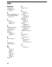
Index Numerics 2 channel 42 2CH STEREO 42 5.1 channel 12 A AUTO CALIBRATION 20 AUTO FORMAT DIRECT (A.F.D.) 37 C CD player connecting 16 playback 26 D Digital Cinema Sound (DCS) 40, 41 Dolby Digital 50 ... 34 TONE 32 TUNER 33 Muting 25 N Naming 46, 47 S Satellite tuner connecting 17 Selecting component 25 sound field 39 Sleep Timer 48 Sound fields resetting 42 selecting 39 Speakers connecting 14 installing 12 Super Audio CD player connecting 16 playback 26 Supplied accessories 57 T TEST TONE 23 Tuner connecting 18...
Index Numerics 2 channel 42 2CH STEREO 42 5.1 channel 12 A AUTO CALIBRATION 20 AUTO FORMAT DIRECT (A.F.D.) 37 C CD player connecting 16 playback 26 D Digital Cinema Sound (DCS) 40, 41 Dolby Digital 50 ... 34 TONE 32 TUNER 33 Muting 25 N Naming 46, 47 S Satellite tuner connecting 17 Selecting component 25 sound field 39 Sleep Timer 48 Sound fields resetting 42 selecting 39 Speakers connecting 14 installing 12 Super Audio CD player connecting 16 playback 26 Supplied accessories 57 T TEST TONE 23 Tuner connecting 18...
Service Manual
Page 1
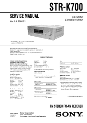
...can change the tuning scale. To reset the scale to 9 kHz or 10 kHz. FM STEREO FM-AM RECEIVER 9-887-073-01 2006A1678-1 © 2006.01 Sony Corporation Home Audio Division Published by Sony Techno Create Corporation Continued on the ...sound field settings and the source, there may be erased when you change the AM tuning scale to 10 kHz (or 9 kHz), repeat the procedure. - SERVICE MANUAL Ver. 1.0 2006.01 STR-K700...
...can change the tuning scale. To reset the scale to 9 kHz or 10 kHz. FM STEREO FM-AM RECEIVER 9-887-073-01 2006A1678-1 © 2006.01 Sony Corporation Home Audio Division Published by Sony Techno Create Corporation Continued on the ...sound field settings and the source, there may be erased when you change the AM tuning scale to 10 kHz (or 9 kHz), repeat the procedure. - SERVICE MANUAL Ver. 1.0 2006.01 STR-K700...
Service Manual
Page 10
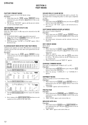
...II x DTS-ES NEO:6 MPEG-2 AAC RDS MEMORY SP B SLEEP OPT COAX MULTI CH IN 96/24 D.RANGE EQ STEREO MONO DIRECT C SL SR kHz mft. Use this mode is displayed. CLR." The model name, destination and the software ...x DTS-ES NEO:6 MPEG-2 AAC RDS MEMORY SP B SLEEP OPT COAX MULTI CH IN 96/24 D.RANGE EQ STEREO MONO DIRECT dB kHz mft. Turn the INPUT SELECTOR dial once again. appears and initialization is command mode changed to...main power. 2. All segments turn on . The message "SF. STR-K700 SECTION 2 TEST MODE FACTORY PRESET MODE All preset contents are reset to AV 1 or AV2.
...II x DTS-ES NEO:6 MPEG-2 AAC RDS MEMORY SP B SLEEP OPT COAX MULTI CH IN 96/24 D.RANGE EQ STEREO MONO DIRECT C SL SR kHz mft. Use this mode is displayed. CLR." The model name, destination and the software ...x DTS-ES NEO:6 MPEG-2 AAC RDS MEMORY SP B SLEEP OPT COAX MULTI CH IN 96/24 D.RANGE EQ STEREO MONO DIRECT dB kHz mft. Turn the INPUT SELECTOR dial once again. appears and initialization is command mode changed to...main power. 2. All segments turn on . The message "SF. STR-K700 SECTION 2 TEST MODE FACTORY PRESET MODE All preset contents are reset to AV 1 or AV2.
Service Manual
Page 13
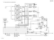
... to same as L-CH. BLOCK DIAGRAM - L • Signal Path : FM A MAIN SECTION SL (Page 12) C FL101 FLUORESCENT INDICATOR TUBE SBL F1 ...+2.5V +5V IC1901 2 +3.3V REG 4 5 +2.5V REG IC1031 3 +5V REG 1 D804-807 T901 IC102 REMOTE 1 CONTROL RECEIVER IC850(1/2) IC850(2/2) 2 15 7 POWER AMP -B Q851,852 -B SWITCH D811 +B -B AUDIO +5V FL101 -20V Q801 -20V REG ...3 -7V REG 2 IC1902 3 +10V REG 1 +3.3V(STBY) IC1111 1 RESET 2 Q911 AC DET IC1904 3 +3.3V REG 1 R803 D920-923 F1 F2 D910-913 T902 D914 Q901 RELAY DRIVE D915 RY901 STR-K700 13 13 STR-K700 AC IN
... to same as L-CH. BLOCK DIAGRAM - L • Signal Path : FM A MAIN SECTION SL (Page 12) C FL101 FLUORESCENT INDICATOR TUBE SBL F1 ...+2.5V +5V IC1901 2 +3.3V REG 4 5 +2.5V REG IC1031 3 +5V REG 1 D804-807 T901 IC102 REMOTE 1 CONTROL RECEIVER IC850(1/2) IC850(2/2) 2 15 7 POWER AMP -B Q851,852 -B SWITCH D811 +B -B AUDIO +5V FL101 -20V Q801 -20V REG ...3 -7V REG 2 IC1902 3 +10V REG 1 +3.3V(STBY) IC1111 1 RESET 2 Q911 AC DET IC1904 3 +3.3V REG 1 R803 D920-923 F1 F2 D910-913 T902 D914 Q901 RELAY DRIVE D915 RY901 STR-K700 13 13 STR-K700 AC IN
Service Manual
Page 29
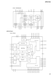
... 24 SEG11/KS11 23 SEG10/KS10 SEG1/KS1 SEG2/KS2 SEG3/KS3 SEG4/KS4 SEG5/KS5 SEG6/KS6 SEG7/KS7 SEG8/KS8 SEG9/KS9 29 STR-K700 AGND VCC C PR C NR C PR C NR VDD DGND SYSCLK DOUT BCK LRCK IC1401 PCM1800E/2K 24 23 22 21 20 19 18 17 16 15...; MODULATOR 1/64 DECIMATION FILTER & LOW-CUT FILTER SERIAL I/O INTERFACE & MODE/FORMAT CONTROL SINGLE-END DEFERENTIAL CONVERTER 1 REFERENCE 234 SINGLE-END DEFERENTIAL CONVERTER 5 CLOCK/ TIMING CONTROL RESET/ POWER CONTROL 6 789 10 11 12 RSTB BYPASS FMT0 FMT1 MODE0 MODE1 FSYNC LIN V REF 1 REFCOM V REF 2 RIN - DISPLAY Board -
... 24 SEG11/KS11 23 SEG10/KS10 SEG1/KS1 SEG2/KS2 SEG3/KS3 SEG4/KS4 SEG5/KS5 SEG6/KS6 SEG7/KS7 SEG8/KS8 SEG9/KS9 29 STR-K700 AGND VCC C PR C NR C PR C NR VDD DGND SYSCLK DOUT BCK LRCK IC1401 PCM1800E/2K 24 23 22 21 20 19 18 17 16 15...; MODULATOR 1/64 DECIMATION FILTER & LOW-CUT FILTER SERIAL I/O INTERFACE & MODE/FORMAT CONTROL SINGLE-END DEFERENTIAL CONVERTER 1 REFERENCE 234 SINGLE-END DEFERENTIAL CONVERTER 5 CLOCK/ TIMING CONTROL RESET/ POWER CONTROL 6 789 10 11 12 RSTB BYPASS FMT0 FMT1 MODE0 MODE1 FSYNC LIN V REF 1 REFCOM V REF 2 RIN - DISPLAY Board -
Service Manual
Page 31
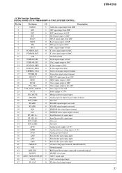
... output to DAC 11 VSS - Analog power supply (+3.3V) 36 AVRH I VACS control signal input 47 FL_LAT O FL driver latch signal output STR-K700 31 Not used 35 AVCC - Not used 34 NOT_USED - • IC Pin Function Description DIGITAL BOARD IC1101 MB90488BPF-G-174E1 (SYSTEM CONTROL) Pin ...output to DSP 7 PM O PM signal output to DSP 8 GP12 O GP12 signal output to DSP 9 PCM1800_RST O IC reset signal output to ADC 10 PCM1608_RST O IC reset signal output to the ASP 23 VCC5 - Ground terminal 43 RDS_SIG I RDS signal detect input (connected to ground terminal) 44...
... output to DAC 11 VSS - Analog power supply (+3.3V) 36 AVRH I VACS control signal input 47 FL_LAT O FL driver latch signal output STR-K700 31 Not used 35 AVCC - Not used 34 NOT_USED - • IC Pin Function Description DIGITAL BOARD IC1101 MB90488BPF-G-174E1 (SYSTEM CONTROL) Pin ...output to DSP 7 PM O PM signal output to DSP 8 GP12 O GP12 signal output to DSP 9 PCM1800_RST O IC reset signal output to ADC 10 PCM1608_RST O IC reset signal output to the ASP 23 VCC5 - Ground terminal 43 RDS_SIG I RDS signal detect input (connected to ground terminal) 44...
Service Manual
Page 32
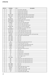
... output (Not used - Not used O LRCK signal output to the selector O Reset signal output to DIR O CKSEL control signal output to DIR O Clock signal output to DIR O Chip enable signal output to DIR STR-K700 Pin No. 48 49 50 51 52 53 54 55 56 57 58 59 ... SIRCS HP_DETECT POWER_KEY ADCC_DSP_IN POWER RY FL_DATA FL_CLK PROTECTOR HP_RY FUSE_DETECT VOL_ENC (A) VOL_ENC (B) FRONT_RY C/SB_RY REAR_RY NOT_USED NOT_USED NOT_USED NOT_USED DO SLATCH TUNED STEREO RSTX MUTE X1A X0A VSS X0 X1 VCC3 NOT_USED SW1 SW2 SW3 SW4 NOT_USED NOT_USED LRCK_SW XMODE CKSEL 1 CLK CE I/O Description I AC off...
... output (Not used - Not used O LRCK signal output to the selector O Reset signal output to DIR O CKSEL control signal output to DIR O Clock signal output to DIR O Chip enable signal output to DIR STR-K700 Pin No. 48 49 50 51 52 53 54 55 56 57 58 59 ... SIRCS HP_DETECT POWER_KEY ADCC_DSP_IN POWER RY FL_DATA FL_CLK PROTECTOR HP_RY FUSE_DETECT VOL_ENC (A) VOL_ENC (B) FRONT_RY C/SB_RY REAR_RY NOT_USED NOT_USED NOT_USED NOT_USED DO SLATCH TUNED STEREO RSTX MUTE X1A X0A VSS X0 X1 VCC3 NOT_USED SW1 SW2 SW3 SW4 NOT_USED NOT_USED LRCK_SW XMODE CKSEL 1 CLK CE I/O Description I AC off...


