Sony STR-K700 Support Question
Sony STR-K700 Support Question
Find answers below for this question about Sony STR-K700 - Fm Stereo/fm-am Receiver.Need a Sony STR-K700 manual? We have 5 online manuals for this item!
Question posted by cocfat on May 15th, 2014
How To Reset A Sony Str K700
The person who posted this question about this Sony product did not include a detailed explanation. Please use the "Request More Information" button to the right if more details would help you to answer this question.
Current Answers
Answer #1: Posted by online24h on May 28th, 2014 3:05 PM
online24h
Member since:
March 28th, 2014 Points: 531,660

Member since:
March 28th, 2014 Points: 531,660
Hello
Download user read page 10
Hope this will be helpful "PLEASE ACCEPT"
Related Sony STR-K700 Manual Pages
Marketing Specifications (HTDDW700 Home Theater System) - Page 2
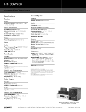
...• 1-800-222-7669 • www.sony.com
Last Updated: 04/04/2006 HT-DDW700
Component Home Theater System
Specifications
Receiver
Audio Audio Power Output: 800W (133w x 5 + 135w
(1KHz, 10% THD))
Inputs and Outputs Analog Audio Input(s): 4 (Rear) Antenna Terminal(s): Yes (FM 75ohms, AM
Loop) Coaxial Audio Digital Input(s): 1 (Rear) Optical Audio Input(s): 1 (Rear)
Power Power Requirements: AC...
Operating Instructions - Page 3
... Systems, Inc.
3US Sub woofer
SS-WP700
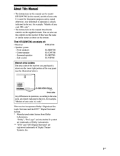
About area codes
The area code of the receiver you purchased is clearly indicated in the text, for model HT-DDW700. Any difference in ... ** "DTS" and "DTS Digital Surround" are registered trademarks of :
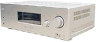
• Receiver
STR-K700
• Speaker system
- Front speakers
SS-MSP700
- Surround speakers
SS-SRP700
- You can also use the controls on...
Operating Instructions - Page 53
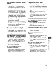
...; Check that sound is output from the audio components. • The plugs and jacks are dirty.
Dolby Digital or DTS Multi Channel sound is recorded in Dolby Digital or DTS format.
• When connecting the DVD player, etc.
uogetwoiui leuomppv
continued 53us to the receiver correctly. There is no sound from one channel...
Service Manual - Page 1
... Impedance: 75 ohms
Sensitivity: - While holding down DIMMER, press ?/1. To reset the scale to 9 kHz or 10 kHz. SPECIFICATIONS
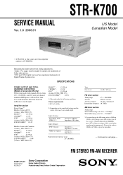
POWER OUTPUT AND TOTAL ...FM STEREO FM-AM RECEIVER
9-887-073-01
2006A1678-1 © 2006.01
Sony Corporation
Home Audio Division Published by Sony Techno Create Corporation
SERVICE MANUAL
Ver. 1.0 2006.01
STR-K700
US Model Canadian Model
• STR-K700...
Service Manual - Page 2
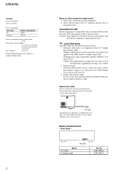
.... About area codes
The area code of the receiver you purchased is best to use of unleaded solder...ordinary solder It is shown on chip component replacement • Never reuse a disconnected chip component. • Notice that the minus side....
• Unleaded solder melts at a temperature about 350 °C.
STR-K700
General Power requirements 120 V AC, 60 Hz
Power consumption Area code...
Service Manual - Page 3
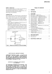
... DIGITAL Board (3/3 18 3-8. REPLACE THESE COMPONENTS WITH SONY PARTS WHOSE PART NUMBERS APPEAR AS SHOWN IN THIS MANUAL OR IN SUPPLEMENTS PUBLISHED BY SONY. NE REMPLACER CES COM- LEAKAGE TEST... COMPONENTS IDENTIFIED BY MARK 0 OR DOTTED LINE WITH MARK 0 ON THE SCHEMATIC DIAGRAMS AND IN THE PARTS LIST ARE CRITICAL TO SAFE OPERATION. MAIN Section 12 3-2. Printed Wiring Board - STR-K700...
Service Manual - Page 4
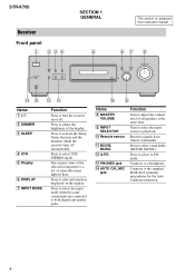
... select 2CH STEREO mode. Turn to select the input source to adjust the volume level of all speakers at the same time.
The current status of the selected component or a list of the display. M PHONES jack N AUTO CAL MIC
jack
Function
Turn to playback. Press to turn the receiver on the display. STR-K700
Receiver
Front...
Service Manual - Page 5
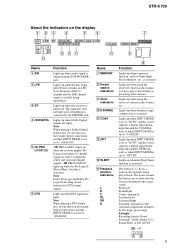
... when audio signal ... the surround components obtained by ... SR
qd qs qa
MEMORY D.RANGE STEREO MONO
0
9
qf 8
Name
Function...STR-K700
About the indicators on presetting radio stations. DIGITAL ;
Lights up when the Pro Logic II Movie/Music decoder is turned on.
"; "; PRO LOGIC II" lights up when the receiver is activated. Lights up when using the receiver to show how the receiver...
Service Manual - Page 6
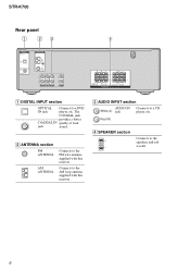
... ANTENNA
Connects to the FM wire antenna supplied with this receiver . C AUDIO INPUT section
AUDIO IN Connects to the speakers and sub woofer.
6 Red (R)
D SPEAKER section
Connects to a CD
White (L) jack
player, etc.
STR-K700
Rear panel
1
23
4
DIGITAL OPTICAL
VIDEO 2 IN
DVD IN COAXIAL
ANTENNA
AM
L L
R R
AUDIO IN AUDIO IN AUDIO IN
S
DVD VIDEO 2
L
R AUDIO IN VIDEO 1
RL
RL...
Service Manual - Page 7
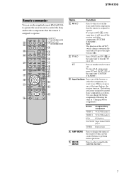
... to select the component you press the input buttons (C).
qa qs
qd
RETURN/EXIT
MENU
TV CH - TUNING +
m
H
M qg
TV
X
x
Name
Function
A AV ?/1
Press to turn off .
STR-K700
Remote commander
You can change the button assignments following the steps in tuner
D AMP MENU
E MOVIE, MUSIC
Press to display the menu of the receiver.
Service Manual - Page 8
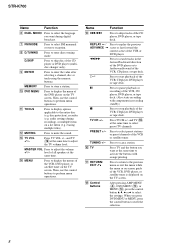
... time to activate the buttons with components in the forward/backward direction of ... CH +/-
Press to select FM monaural or stereo reception. Press to return to...to display options applicable to mute the sound. audio settings during digital broadcast. L MUTING
Press ...button V, v, B or b to select preset TV channels.
STR-K700
Name
Function
F DUAL MONO Press to select the language you ...
Service Manual - Page 9
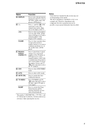
... press the incorrect numeric buttons or to return to select A.F.D.
Press to continuous playback, etc.
Therefore, depending on the component, the above explanation is intended to serve as references when operating the receiver. STR-K700
Name
Function
S DISPLAY
Press to select the information displayed on the TV screen of the satellite tuner or DVD...
Service Manual - Page 10
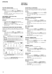
...mode is displayed. SHIPMENT MODE All preset contents are reset to turn on the main power. 3. While depressing... to turn on the main power.
2. PROTECTOR Procedure:
1.
STR-K700
SECTION 2 TEST MODE
FACTORY PRESET MODE All preset contents are ...RDS MEMORY SP B SLEEP OPT COAX MULTI CH IN 96/24 D.RANGE EQ STEREO MONO DIRECT
C
SL
SR
kHz
mft.
Every pressing of the INPUT SELECTOR ...
Service Manual - Page 11
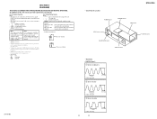
... board
STR-K700
ADCC board HEADPHONE board DISPLAY board
DIGITAL board
• Waveforms - Caution: Pattern face side: (Side A) Parts face side: (Side B)
Parts on the parts face side seen from the pattern face are indicated. Replace only with a VOM (Input impedance 10 MΩ). F : FM J : ANALOG c : DIGITAL
• Indication of transistor.
Note: The components identified...
Service Manual - Page 13
...
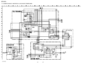
D811 +B -B
AUDIO +5V
FL101 -20V
Q801 -20V REG
IC1001
3
+5V REG
1
RELAY +B
AUDIO +7V
AUDIO -7V
TUNER +10V
IC821
1
+7V REG
3
IC822
3
-7V REG
2
IC1902
3
+10V REG
1
+3.3V(STBY)
IC1111 1 RESET 2
Q911 AC DET
IC1904
3
+3.3V REG
1
R803 D920-923
F1 F2
D910-913
T902
D914
Q901 RELAY DRIVE
D915 RY901
STR-K700
13
13
STR-K700
AC...
Service Manual - Page 14
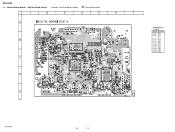
No. D1001 D1301 D1302
Location
B-5 C-2 C-2
IC1101 D-5 IC1111 C-6 IC1131 E-5 IC1301 B-2 IC1303 C-2 IC1401 E-2 IC1452 D-3 IC1501 D-4 IC1502 B-4 IC1503 D-4
STR-K700
14
14 STR-K700
3-3. DIGITAL BOARD (SIDE A) - • See page 11 for Circuit Boards Location.
:Uses unleaded solder.
1
2
3
4
5
6
7
A
B
48 IC1301
1
37 36
12 13
25 24
IC1502
C
IC1303
120
...
Service Manual - Page 22
...
C2013 1
50V
D2014 ISS133T-72
D2013 ISS133T-72
C2014 0.47 50V
TP2000 CHASSIS GND
R2015 33k
R2016 15k
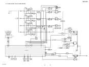
STR-K700
CNP801 5P
CNP906 5P
C915 2200 25V
C916 1000 25V
D920 10EDB40-TA2B5
D921 10EDB40-TA2B5
R810 0.22 D923 ... R900 3.3M
G901 EARTH TERMINAL
CNP903 3P CNP904 2P
CNP900 2P
No mark : FM
22
22 MAIN BOARD (3/3), ADCC BOARD, STANDBY BOARD - SCHEMATIC DIAGRAM -
STR-K700
3-11.
Service Manual - Page 29
...KS2 SEG3/KS3 SEG4/KS4 SEG5/KS5 SEG6/KS6 SEG7/KS7 SEG8/KS8 SEG9/KS9
29 DISPLAY Board - STR-K700
AGND VCC C PR C NR C PR C NR VDD DGND SYSCLK DOUT BCK LRCK
IC1401 PCM1800E/2K...SINGLE-END DEFERENTIAL CONVERTER
1
REFERENCE 234
SINGLE-END DEFERENTIAL CONVERTER
5
CLOCK/ TIMING CONTROL RESET/
POWER CONTROL
6
789
10 11 12
RSTB BYPASS
FMT0 FMT1 MODE0 MODE1 FSYNC
LIN V REF 1 REFCOM V REF 2
RIN
...
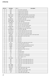
Service Manual - Page 31
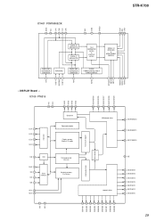
... signal output to DSP
9
PCM1800_RST
O IC reset signal output to ADC
10
PCM1608_RST
O IC reset signal output to DAC
11
VSS
- Ground ...35
AVCC
- Not used
34
NOT_USED
- Pin Name
I/O
Description
1
DATAO
I Audio data signal input from DIR
2
GP9
I GP9 signal input from DSP
3
BST
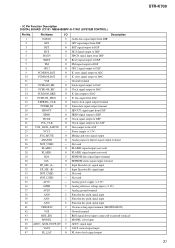
...STR-K700 31 • IC Pin Function Description DIGITAL BOARD IC1101 MB90488BPF-G-174E1 ...
Service Manual - Page 32
...used
- Not used
O LRCK signal output to the selector
O Reset signal output to DIR
O CKSEL control signal output to DIR
O ... (+3.3V)
- Not used )
- Ground terminal
- Ground terminal
- STR-K700
Pin No. 48 49 50 51 52 53 54 55 56 57 58... from rotary encoder
I Volume signal input from the tuner
I Stereo tuning signal input from rotary encoder
O Front speaker relay control...
Similar Questions

Str-k700 Need To Know How To Change The Station?
want to find out how to navigate the stations and preset the
want to find out how to navigate the stations and preset the
(Posted by javiez1966 2 years ago)

Sony Str K700 With No Remote
How so I change the radio stations on my Sony STR K700 without the remote?
How so I change the radio stations on my Sony STR K700 without the remote?
(Posted by brian7hunter 2 years ago)

How To Reset Str-k840p Receiver
(Posted by Golbbb 10 years ago)

What Is The Code To Program The Remote Control For My Sony Str-k700-fm Receiver
(Posted by rickcharles246 11 years ago)