Marketing Specifications (HTDDW700 Home Theater System)
Page 2
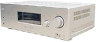
... Network for current information at www.sony.com/dn Sony Electronics Inc. • 16530 Via Esprillo • San Diego, CA 92127 • 1-800-222-7669 • www.sony.com Last Updated: 04/04/2006 HT-DDW700 Component Home Theater System Specifications Receiver Audio Audio Power Output: 800W ...(133w x 5 + 135w (1KHz, 10% THD)) Inputs and Outputs Analog Audio Input(s): 4 (Rear) Antenna Terminal(s): Yes (FM 75ohms, AM Loop) Coaxial Audio...
... Network for current information at www.sony.com/dn Sony Electronics Inc. • 16530 Via Esprillo • San Diego, CA 92127 • 1-800-222-7669 • www.sony.com Last Updated: 04/04/2006 HT-DDW700 Component Home Theater System Specifications Receiver Audio Audio Power Output: 800W ...(133w x 5 + 135w (1KHz, 10% THD)) Inputs and Outputs Analog Audio Input(s): 4 (Rear) Antenna Terminal(s): Yes (FM 75ohms, AM Loop) Coaxial Audio...

Operating Instructions
Page 2
...Article 820-40 of cable entry as practical. 2US If this equipment does cause harmful interference to radio or television reception, which the receiver is intended to alert the user to the presence of uninsulated "dangerous voltage" within the product's enclosure that the cable ground shall... be connected to the grounding system of the following measures: Reorient or relocate the receiving antenna. To prevent fire, do not place objects filled with general house waste; Consult the dealer or an experienced radio/TV technician for...
...Article 820-40 of cable entry as practical. 2US If this equipment does cause harmful interference to radio or television reception, which the receiver is intended to alert the user to the presence of uninsulated "dangerous voltage" within the product's enclosure that the cable ground shall... be connected to the grounding system of the following measures: Reorient or relocate the receiving antenna. To prevent fire, do not place objects filled with general house waste; Consult the dealer or an experienced radio/TV technician for...
Operating Instructions
Page 3
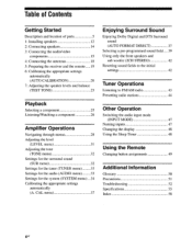
...** Digital Surround System. • Manufactured under license from Dolby Laboratories. Any difference in operation is clearly indicated in the text, for example, "Models of the receiver you purchased is used for model HT-DDW700. Surround speakers SS-SRP700 - "Dolby", "Pro Logic" and the double-D symbol are trademarks of Dolby Laboratories. ** "DTS... woofer SS-WP700 About area codes The area code of area code CEL only". • The instructions in this manual are registered trademarks of : • Receiver STR-K700 • Speaker system - Center speaker SS-CNP700 -
...** Digital Surround System. • Manufactured under license from Dolby Laboratories. Any difference in operation is clearly indicated in the text, for example, "Models of the receiver you purchased is used for model HT-DDW700. Surround speakers SS-SRP700 - "Dolby", "Pro Logic" and the double-D symbol are trademarks of Dolby Laboratories. ** "DTS... woofer SS-WP700 About area codes The area code of area code CEL only". • The instructions in this manual are registered trademarks of : • Receiver STR-K700 • Speaker system - Center speaker SS-CNP700 -
Operating Instructions
Page 4
... 5 1: Installing speakers 12 2: Connecting speakers 14 3: Connecting the audio/video components 15 4: Connecting the antennas 18 5: Preparing the receiver and the remote 19 6: Calibrating the appropriate settings automatically (AUTO CALIBRATION) 20 7: Adjusting the speaker levels and balance (TEST TONE) ...pre-programmed sound field 39 Using only the front speakers and sub woofer (2CH STEREO) 42 Resetting sound fields to the initial settings 42 Tuner Operations Listening to FM/AM radio 43 Presetting radio stations 44 Other Operation Switching the audio input mode...
... 5 1: Installing speakers 12 2: Connecting speakers 14 3: Connecting the audio/video components 15 4: Connecting the antennas 18 5: Preparing the receiver and the remote 19 6: Calibrating the appropriate settings automatically (AUTO CALIBRATION) 20 7: Adjusting the speaker levels and balance (TEST TONE) ...pre-programmed sound field 39 Using only the front speakers and sub woofer (2CH STEREO) 42 Resetting sound fields to the initial settings 42 Tuner Operations Listening to FM/AM radio 43 Presetting radio stations 44 Other Operation Switching the audio input mode...
Operating Instructions
Page 5
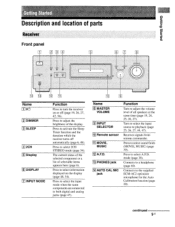
...5 6 Name 1 ii(1) 121 DIMMER 3 SLEEP 4 2CH 5 Display 6 DISPLAY 7 INPUT MODE Function Press to turn the receiver on the display (page 48, 54). Turn to select the input source to select 2CH STEREO mode (page 34). continued 51.1S Press to playback (page 25, 26, 27, 44, 47). Press to adjust... PHONES jack 14 AUTO CAL MIC jack Function Turn to activate the Sleep Timer function and the duration which the receiver turns off (page 19, 26, 27, 42, 56). Receives signals from remote commander. Press to the supplied ECM-AC2 optimizer microphone for the Auto Calibration function (page 20)....
...5 6 Name 1 ii(1) 121 DIMMER 3 SLEEP 4 2CH 5 Display 6 DISPLAY 7 INPUT MODE Function Press to turn the receiver on the display (page 48, 54). Turn to select the input source to select 2CH STEREO mode (page 34). continued 51.1S Press to playback (page 25, 26, 27, 44, 47). Press to adjust... PHONES jack 14 AUTO CAL MIC jack Function Turn to activate the Sleep Timer function and the duration which the receiver turns off (page 19, 26, 27, 42, 56). Receives signals from remote commander. Press to the supplied ECM-AC2 optimizer microphone for the Auto Calibration function (page 20)....
Operating Instructions
Page 6
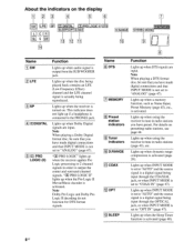
...the display 1 4 15 LFE L C R SL SR 14 SLEEP roTTCOAX 113 MEMORY D.RANGEI STEREO MON 10 191 ••• Name 1 SW 2 LFE 3 SP 4 DODIGITAL 5 DO PRO LOGIC (II) Function Lights up when using the receiver to tune in order to "ANALOG" (page 47). "00 PRO LOGIC" lights up when... using the receiver to tune in radio stations you have preset. Lights up when the receiver applies Pro Logic processing to 2 channel signals in radio stations (...
...the display 1 4 15 LFE L C R SL SR 14 SLEEP roTTCOAX 113 MEMORY D.RANGEI STEREO MON 10 191 ••• Name 1 SW 2 LFE 3 SP 4 DODIGITAL 5 DO PRO LOGIC (II) Function Lights up when using the receiver to tune in order to "ANALOG" (page 47). "00 PRO LOGIC" lights up when... using the receiver to tune in radio stations you have preset. Lights up when the receiver applies Pro Logic processing to 2 channel signals in radio stations (...

Operating Instructions
Page 7
pepels Bugle° Name 1141 Playback channel indicators L R C SL SR S Function The letters (L, C, R, etc.) indicate the channels being played back. Front Left Front Right Center (monaural) Surround Left Surround Right Surround (monaural or the surround components obtained by Pro Logic processing) Example: Recording format (Front/ Surround): Dolby Digital 3/2.1 Sound Field: A.F.D. The boxes around the letters vary to show how the receiver downmixes the source sound. AUTO SW LFE [ c I SL SRI continued 7US
pepels Bugle° Name 1141 Playback channel indicators L R C SL SR S Function The letters (L, C, R, etc.) indicate the channels being played back. Front Left Front Right Center (monaural) Surround Left Surround Right Surround (monaural or the surround components obtained by Pro Logic processing) Example: Recording format (Front/ Surround): Dolby Digital 3/2.1 Sound Field: A.F.D. The boxes around the letters vary to show how the receiver downmixes the source sound. AUTO SW LFE [ c I SL SRI continued 7US
Operating Instructions
Page 8
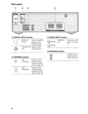
Bus Connects to the AM loop antenna supplied with this receiver (page 18). 3 AUDIO INPUT section AUDIO IN O White (L) jack O Red (R) Connects to a CD player, etc. (page 16). 141 SPEAKER section Connects to the FM wire antenna supplied with this receiver (page 18). The COAXIAL jack provides a better COAXIAL IN quality of loud jack sound (page 17). 2 ANTENNA section FM 0 ANTENNA AM ANTENNA Connects to the speakers and sub woofer (page 14). Rear panel [ 1 t" C DIGITAL INPUT section OPTICAL Connects to a DVD IN jack player, etc.
Bus Connects to the AM loop antenna supplied with this receiver (page 18). 3 AUDIO INPUT section AUDIO IN O White (L) jack O Red (R) Connects to a CD player, etc. (page 16). 141 SPEAKER section Connects to the FM wire antenna supplied with this receiver (page 18). The COAXIAL jack provides a better COAXIAL IN quality of loud jack sound (page 17). 2 ANTENNA section FM 0 ANTENNA AM ANTENNA Connects to the speakers and sub woofer (page 14). Rear panel [ 1 t" C DIGITAL INPUT section OPTICAL Connects to a DVD IN jack player, etc.
Operating Instructions
Page 9
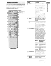
...I /03 (on/standby) switch TV il(!), i/(1) (on or off the Sony audio/video components that the remote is assigned to operate. You can use the supplied remote RM-AAU006 to operate the receiver and to control the Sony audio/video components that the remote is assigned to operate (page 49). Then..., use . To turn off the receiver and other components (SYSTEM STANDBY). papeis BumeD Remote commander You can ...
...I /03 (on/standby) switch TV il(!), i/(1) (on or off the Sony audio/video components that the remote is assigned to operate. You can use the supplied remote RM-AAU006 to operate the receiver and to control the Sony audio/video components that the remote is assigned to operate (page 49). Then..., use . To turn off the receiver and other components (SYSTEM STANDBY). papeis BumeD Remote commander You can ...
Operating Instructions
Page 11
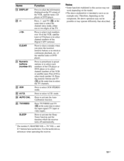
...Calibration function. Press TV/VIDEO and TV ( 16 ) at the same time to activate the Sleep Timer function and the duration which the receiver turns off automatically. CLEAR 1211 Numeric buttons (number 5*) 22 2CH 1231 A.F.D. 24 AUTO CAL 1251 TVNIDEO SLEEP Function Press to select the ...may operate differently than described. 110s Press to serve as references when operating the receiver. Press to select track numbers over 10 of the VCR, satellite tuner or CD player or to select 2CH STEREO mode. Therefore, depending on the component, the above operation may not be ...
...Calibration function. Press TV/VIDEO and TV ( 16 ) at the same time to activate the Sleep Timer function and the duration which the receiver turns off automatically. CLEAR 1211 Numeric buttons (number 5*) 22 2CH 1231 A.F.D. 24 AUTO CAL 1251 TVNIDEO SLEEP Function Press to select the ...may operate differently than described. 110s Press to serve as references when operating the receiver. Press to select track numbers over 10 of the VCR, satellite tuner or CD player or to select 2CH STEREO mode. Therefore, depending on the component, the above operation may not be ...

Operating Instructions
Page 15
COAXIA IN OPTICAL IN Digital OAURDINIO Analog High quality sound 1 5US Audio input jack to the illustration that follows. Refer to be connected The sound quality depends on the connecting jack. After hooking up your components to "4: Connecting the antennas" (page 18). papels BumeD 3: Connecting the audio/video components How to hook up your components This section describes how to hook up all your components, proceed to this receiver. Select the connection according to the jacks of your components.
COAXIA IN OPTICAL IN Digital OAURDINIO Analog High quality sound 1 5US Audio input jack to the illustration that follows. Refer to be connected The sound quality depends on the connecting jack. After hooking up your components to "4: Connecting the antennas" (page 18). papels BumeD 3: Connecting the audio/video components How to hook up your components This section describes how to hook up all your components, proceed to this receiver. Select the connection according to the jacks of your components.
Operating Instructions
Page 17
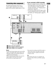
... place. • Do not bend or tie optical digital cords. • You cannot do recording on the DVD recorder or VCR via this receiver. it can be displayed on the DVD player. Refer to the operating instructions supplied with 32 kHz, 44.1 kHz, 48 kHz, and 96... Coaxial digital cord (supplied) Notes • To input multi channel digital audio from the DVD player, set the digital audio output setting on the receiver's display. papels Bu!nap Connecting video components The following illustration shows how to control your DVD recorder. For details, see "Changing button assignments" (...
... place. • Do not bend or tie optical digital cords. • You cannot do recording on the DVD recorder or VCR via this receiver. it can be displayed on the DVD player. Refer to the operating instructions supplied with 32 kHz, 44.1 kHz, 48 kHz, and 96... Coaxial digital cord (supplied) Notes • To input multi channel digital audio from the DVD player, set the digital audio output setting on the receiver's display. papels Bu!nap Connecting video components The following illustration shows how to control your DVD recorder. For details, see "Changing button assignments" (...

Operating Instructions
Page 18
FM wire antenna (supplied) * • DIGITAL CAL : •M ?h, COgIAL .SCW,AL La L O FjP10 I R 0 .1JIO VIDEO 1 * The shape of the connector varies depending on the area code of this receiver. 4: Connecting the antennas Connect the supplied AM loop antenna and FM wire antenna. Notes • To prevent noise pickup, keep the AM loop antenna away from the receiver and other components. • Be sure to fully extend the FM wire antenna. • After connecting the FM wire antenna, keep it as horizontal as possible. AM loop antenna (supplied) SUB WOOFER L SURROUND 18us
FM wire antenna (supplied) * • DIGITAL CAL : •M ?h, COgIAL .SCW,AL La L O FjP10 I R 0 .1JIO VIDEO 1 * The shape of the connector varies depending on the area code of this receiver. 4: Connecting the antennas Connect the supplied AM loop antenna and FM wire antenna. Notes • To prevent noise pickup, keep the AM loop antenna away from the receiver and other components. • Be sure to fully extend the FM wire antenna. • After connecting the FM wire antenna, keep it as horizontal as possible. AM loop antenna (supplied) SUB WOOFER L SURROUND 18us
Operating Instructions
Page 19
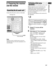
... stations. • MASTER VOLUME is set to "VOL MIN". • Input is set to their factory defaults. After "CLEARING" appears on the receiver for this operation. 1,2 U FRONT To the wall outlet Note Install this system so that the power cord can also be unplugged from the wall socket... input and preset station. • All sound field parameters. • All preset stations. • All index names for the first time, initialize the receiver by performing the following items are reset to "DVD". 19us Be sure to their factory settings. • All settings in the event of trouble. 1...
... stations. • MASTER VOLUME is set to "VOL MIN". • Input is set to their factory defaults. After "CLEARING" appears on the receiver for this operation. 1,2 U FRONT To the wall outlet Note Install this system so that the power cord can also be unplugged from the wall socket... input and preset station. • All sound field parameters. • All preset stations. • All index names for the first time, initialize the receiver by performing the following items are reset to "DVD". 19us Be sure to their factory settings. • All settings in the event of trouble. 1...

Operating Instructions
Page 20
...so may cause a malfunction. • If you to perform automatic calibration as follows: • Check the connection between each speaker and the receiver. • Adjust the speaker level. • Measure the distance of each speaker to use the remote for about 3 months. Tip Under ... possible damage from battery leakage and corrosion. When the remote no longer operates the receiver, replace all the batteries with new ones. 6: Calibrating the appropriate settings automatically (AUTO CALIBRATION) This receiver is equipped with old ones. • Do not mix alkaline batteries and other ...
...so may cause a malfunction. • If you to perform automatic calibration as follows: • Check the connection between each speaker and the receiver. • Adjust the speaker level. • Measure the distance of each speaker to use the remote for about 3 months. Tip Under ... possible damage from battery leakage and corrosion. When the remote no longer operates the receiver, replace all the batteries with new ones. 6: Calibrating the appropriate settings automatically (AUTO CALIBRATION) This receiver is equipped with old ones. • Do not mix alkaline batteries and other ...
Operating Instructions
Page 22
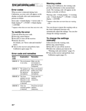
... --. microphone. connection. To rectify the error 1 Record down the warning code. 2 Press the control button. 3 Press l/(!) to turn off the receiver. 4 Follow the solution provided in the "Warning code and solution" (page 23). 5 Turn on the display cyclically after each measurement process as the... further away from the optimizer the optimizer microphone. Warning codes During Auto Calibration, the warning code provides information on the receiver and perform Auto Calibration again (page 21). To change the settings manually. ENTER °Appears when there are more than...
... --. microphone. connection. To rectify the error 1 Record down the warning code. 2 Press the control button. 3 Press l/(!) to turn off the receiver. 4 Follow the solution provided in the "Warning code and solution" (page 23). 5 Turn on the display cyclically after each measurement process as the... further away from the optimizer the optimizer microphone. Warning codes During Auto Calibration, the warning code provides information on the receiver and perform Auto Calibration again (page 21). To change the settings manually. ENTER °Appears when there are more than...

Operating Instructions
Page 23
... WARN. 70 The front speakers Reposition your distance is out of front speakers.° range. MOVIE MUSIC (_) CD DUAL MOHO CD 'C:2j 'CU FM MOD: >I0/• Ps D,SAP MEMORY MO MENU =~„.0Ls MUTING 2-5 MASTER VOL +1- speaker.0 °For details, refer "Front speaker ...distance" (page 34). Tip The receiver employs a test tone with a frequency centered at 800 Hz. RETURN/EAT 1 Press AMP MENU. papels Bumap Warning code and solution Warning Explanation ...
... WARN. 70 The front speakers Reposition your distance is out of front speakers.° range. MOVIE MUSIC (_) CD DUAL MOHO CD 'C:2j 'CU FM MOD: >I0/• Ps D,SAP MEMORY MO MENU =~„.0Ls MUTING 2-5 MASTER VOL +1- speaker.0 °For details, refer "Front speaker ...distance" (page 34). Tip The receiver employs a test tone with a frequency centered at 800 Hz. RETURN/EAT 1 Press AMP MENU. papels Bumap Warning code and solution Warning Explanation ...

Operating Instructions
Page 24
... sequence as follows: Front left ---. Front right ---. For details, see "Adjusting the level (LEVEL menu)" (page 31). You can also use MASTER VOLUME on the receiver. • The adjusted value are shown on the display during adjustment. Tips • To adjust the level of the test tone sounds the same from...
... sequence as follows: Front left ---. Front right ---. For details, see "Adjusting the level (LEVEL menu)" (page 31). You can also use MASTER VOLUME on the receiver. • The adjusted value are shown on the display during adjustment. Tips • To adjust the level of the test tone sounds the same from...
Operating Instructions
Page 25
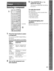
... to DVD jack SA-CD/CD [SA-CD/CD] Super Audio CD/CD player, etc., connected to turn off the receiver. You can be sure to the SA-CD/CD jack TUNER [FM or AM band] Built-in radio tuner 2 Turn on the display. To mute the sound Press MUTING. RETURN/EXIT.... The muting function will be canceled when you turn down the volume level. Selected input [Display] Components that can also use MASTER VOLUME on the receiver. to select a component. TV CH- TYCH» PRESET-- The selected input appears on the component and start playback. 25 US CLEAR DISPLAY OSKIP EMORY DV...
... to DVD jack SA-CD/CD [SA-CD/CD] Super Audio CD/CD player, etc., connected to turn off the receiver. You can be sure to the SA-CD/CD jack TUNER [FM or AM band] Built-in radio tuner 2 Turn on the display. To mute the sound Press MUTING. RETURN/EXIT.... The muting function will be canceled when you turn down the volume level. Selected input [Display] Components that can also use MASTER VOLUME on the receiver. to select a component. TV CH- TYCH» PRESET-- The selected input appears on the component and start playback. 25 US CLEAR DISPLAY OSKIP EMORY DV...

Operating Instructions
Page 26
... all speakers (multi channel). You can also use INPUT SELECTOR on the receiver. 3 Press SA-CD/CD. Listening/Watching a component Listening to a Super Audio CD/CD 1'r 2 3 O o 8 5 3 !!) Notes • The operation is described for a Sony Super Audio CD player. • Refer to page 39 for details. ...1 Turn on the Super Audio CD player/CD player, then place the disc on the tray. 2 Turn on the receiver to select SA-CD/CD. 4 Playback the disc. 5 Adjust to...
... all speakers (multi channel). You can also use INPUT SELECTOR on the receiver. 3 Press SA-CD/CD. Listening/Watching a component Listening to a Super Audio CD/CD 1'r 2 3 O o 8 5 3 !!) Notes • The operation is described for a Sony Super Audio CD player. • Refer to page 39 for details. ...1 Turn on the Super Audio CD player/CD player, then place the disc on the tray. 2 Turn on the receiver to select SA-CD/CD. 4 Playback the disc. 5 Adjust to...


