Limited Warranty (US Only)
Page 1
...the Sony Partnership within the Warranty period must pay for product information or operation, call: Sony Customer Information Services Center 1-800-222-7669 or visit the Sony Web Site: www.sony.com...557-172-02 General Stereo/Hifi Components/Tape Decks ® CD Players/Mini Disc Players/Audio Systems Hifi Audio LIMITED WARRANTY Sony Electronics Inc. ("Sony") warrants this Product is... the Product freight prepaid, in the United States. This warranty does not cover customer instruction, installation, set up adjustments or signal reception problems. This warranty does not cover cosmetic...
...the Sony Partnership within the Warranty period must pay for product information or operation, call: Sony Customer Information Services Center 1-800-222-7669 or visit the Sony Web Site: www.sony.com...557-172-02 General Stereo/Hifi Components/Tape Decks ® CD Players/Mini Disc Players/Audio Systems Hifi Audio LIMITED WARRANTY Sony Electronics Inc. ("Sony") warrants this Product is... the Product freight prepaid, in the United States. This warranty does not cover customer instruction, installation, set up adjustments or signal reception problems. This warranty does not cover cosmetic...
Operating Instructions
Page 1
Record the serial number in the space provided below. Refer to them whenever you call upon your Sony dealer regarding this product. HT-DDW700 ©2006 Sony Corporation Model No. SONY® 2-661-459-12 (2) Home Theatre System Operating Instructions Owner's Record The model and serial numbers are located on the rear of the unit. Serial No.
Record the serial number in the space provided below. Refer to them whenever you call upon your Sony dealer regarding this product. HT-DDW700 ©2006 Sony Corporation Model No. SONY® 2-661-459-12 (2) Home Theatre System Operating Instructions Owner's Record The model and serial numbers are located on the rear of the unit. Serial No.

Operating Instructions
Page 2
.... SNOOK. 00 NOT REMOVE COVER (OR BACK). WARNING This equipment has been tested and found to comply with the instructions, may be of sufficient magnitude to constitute a risk of electric shock to persons. And don't place lighted candles on...receiver is intended to alert the user to the presence of uninsulated "dangerous voltage" within the product's enclosure that any changes or modification not expressly approved in this manual could void your authority to operate this equipment. To prevent fire, do not cover the ventilation of important operating and maintenance (servicing) instructions...
.... SNOOK. 00 NOT REMOVE COVER (OR BACK). WARNING This equipment has been tested and found to comply with the instructions, may be of sufficient magnitude to constitute a risk of electric shock to persons. And don't place lighted candles on...receiver is intended to alert the user to the presence of uninsulated "dangerous voltage" within the product's enclosure that any changes or modification not expressly approved in this manual could void your authority to operate this equipment. To prevent fire, do not cover the ventilation of important operating and maintenance (servicing) instructions...
Operating Instructions
Page 3
...this manual describe the controls on the supplied remote. Front speakers SS-MSP700 - Surround speakers SS-SRP700 - About This Manual • The instructions in the text, for example, "Models of area code AA only". "Dolby", "Pro Logic" and the double-D symbol are trademarks ...panel (see the illustration below). 2-XXX-XXX-XX AA Area code Any differences in operation, according to the area code, are clearly indicated in this manual are registered trademarks of : • Receiver STR-K700 • Speaker system - The HT-DDW700 consists of Digital Theater Systems, Inc. ...
...this manual describe the controls on the supplied remote. Front speakers SS-MSP700 - Surround speakers SS-SRP700 - About This Manual • The instructions in the text, for example, "Models of area code AA only". "Dolby", "Pro Logic" and the double-D symbol are trademarks ...panel (see the illustration below). 2-XXX-XXX-XX AA Area code Any differences in operation, according to the area code, are clearly indicated in this manual are registered trademarks of : • Receiver STR-K700 • Speaker system - The HT-DDW700 consists of Digital Theater Systems, Inc. ...

Operating Instructions
Page 12
... highly directional signals, you can place it wherever you install the speakers and sub woofer, be sure to attach the supplied foot pads to the operating instructions supplied with the speaker stand. 12us 1: Installing speakers To fully enjoy theater-like multi channel surround sound requires five speakers (two front speakers, a center speaker...
... highly directional signals, you can place it wherever you install the speakers and sub woofer, be sure to attach the supplied foot pads to the operating instructions supplied with the speaker stand. 12us 1: Installing speakers To fully enjoy theater-like multi channel surround sound requires five speakers (two front speakers, a center speaker...
Operating Instructions
Page 17
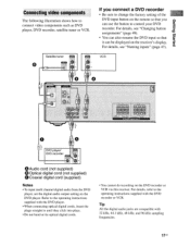
...47). Refer to the operating instructions supplied with the DVD player. • When connecting optical digital cords, insert the plugs straight in until they click into place. • Do not bend or tie optical digital cords. • You cannot do recording on the receiver's display. VCR J. ...recorder • Be sure to control your DVD recorder. papels Bu!nap Connecting video components The following illustration shows how to the operating instructions supplied with the DVD recorder or VCR. For details, refer to connect video components such as DVD player, DVD recorder, satellite ...
...47). Refer to the operating instructions supplied with the DVD player. • When connecting optical digital cords, insert the plugs straight in until they click into place. • Do not bend or tie optical digital cords. • You cannot do recording on the receiver's display. VCR J. ...recorder • Be sure to control your DVD recorder. papels Bu!nap Connecting video components The following illustration shows how to the operating instructions supplied with the DVD recorder or VCR. For details, refer to connect video components such as DVD player, DVD recorder, satellite ...

Operating Instructions
Page 26
Tips • You can also use INPUT SELECTOR on the receiver. 3 Press SA-CD/CD. Refer to page 37 for a Sony Super Audio CD player. • Refer to the operating instructions supplied with the Super Audio CD player or CD player. You can select the sound field to suit the music...component Listening to a Super Audio CD/CD 1'r 2 3 O o 8 5 3 !!) Notes • The operation is described for details. 1 Turn on the Super Audio CD player/CD player, then place the disc on the tray. 2 Turn on the receiver to select SA-CD/CD. 4 Playback the disc. 5 Adjust to a suitable volume. 6 After you...
Tips • You can also use INPUT SELECTOR on the receiver. 3 Press SA-CD/CD. Refer to page 37 for a Sony Super Audio CD player. • Refer to the operating instructions supplied with the Super Audio CD player or CD player. You can select the sound field to suit the music...component Listening to a Super Audio CD/CD 1'r 2 3 O o 8 5 3 !!) Notes • The operation is described for details. 1 Turn on the Super Audio CD player/CD player, then place the disc on the tray. 2 Turn on the receiver to select SA-CD/CD. 4 Playback the disc. 5 Adjust to a suitable volume. 6 After you...

Operating Instructions
Page 27
... You can select the sound field to suit the movie/music. If no image is displayed on the receiver. 3 Press DVD. Watching a DVD 1) 2 3 D 0 0 3 Notes • Refer to the operating instructions supplied with the TV and DVD player. • Check the following if you have finished watching the ...DVD, eject the disc and turn off the receiver, TV and DVD player. 27us Be sure this receiver to select DVD. 4 Switch the input of the TV...
... You can select the sound field to suit the movie/music. If no image is displayed on the receiver. 3 Press DVD. Watching a DVD 1) 2 3 D 0 0 3 Notes • Refer to the operating instructions supplied with the TV and DVD player. • Check the following if you have finished watching the ...DVD, eject the disc and turn off the receiver, TV and DVD player. 27us Be sure this receiver to select DVD. 4 Switch the input of the TV...
Operating Instructions
Page 49
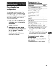
For details, refer to the operating instructions supplied with a DVD 1 or DVD 3 setting. b)Sony DVD recorders are operated with a VTR 2 or VTR 3 setting which you want to change the factory settings of which correspond to 8 mm and VHS respectively. The... recorder. For example, if you connect a DVD recorder to the DVD jacks on the receiver, you can set the DVD button on this receiver) 8 DVR (Digital CATV terminal) 9 DSS (Digital Satellite Receiver) 0/10 °Sony VCRs are operated with the DVD recorders. Example: Press DVD. 2 Referring to its factory settings. Now ...
For details, refer to the operating instructions supplied with a DVD 1 or DVD 3 setting. b)Sony DVD recorders are operated with a VTR 2 or VTR 3 setting which you want to change the factory settings of which correspond to 8 mm and VHS respectively. The... recorder. For example, if you connect a DVD recorder to the DVD jacks on the receiver, you can set the DVD button on this receiver) 8 DVR (Digital CATV terminal) 9 DSS (Digital Satellite Receiver) 0/10 °Sony VCRs are operated with the DVD recorders. Example: Press DVD. 2 Referring to its factory settings. Now ...

Operating Instructions
Page 62
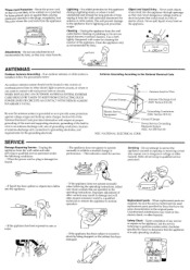
Sony Corporation © 2000 Printed in fire or electric shock. for example, near a bathtub, washbowl, kitchen sink, or laundry tub, in the operating instructions, and adhere to a wall or ceiling, mount it only as a bookcase, or built-in use powerline operated appliances near a swimming pool, etc. 'OD Heat - To ensure reliable operation... of electrical power supplied to the operating instructions. Never cover the slots and openings with a cloth or ...
Sony Corporation © 2000 Printed in fire or electric shock. for example, near a bathtub, washbowl, kitchen sink, or laundry tub, in the operating instructions, and adhere to a wall or ceiling, mount it only as a bookcase, or built-in use powerline operated appliances near a swimming pool, etc. 'OD Heat - To ensure reliable operation... of electrical power supplied to the operating instructions. Never cover the slots and openings with a cloth or ...
Operating Instructions
Page 63
...Attachments - If the appliance has been exposed to qualified service personnel under the following the operating instructions, adjust only those controls that the appliance is grounded so as recommended by Sony) to lightning and powerline surges. SERVICE DEPT z.- Power-Cord Protection - When replacement parts ...are required, be located in the vicinity of the National Electrical Code provides information with water for the grounding electrode. All SETS RECEIVE OUR OK .SAFETY CHECK. Do not attempt to be walked on the appliance. //Mil /III \ \ \\ o QOOO ...
...Attachments - If the appliance has been exposed to qualified service personnel under the following the operating instructions, adjust only those controls that the appliance is grounded so as recommended by Sony) to lightning and powerline surges. SERVICE DEPT z.- Power-Cord Protection - When replacement parts ...are required, be located in the vicinity of the National Electrical Code provides information with water for the grounding electrode. All SETS RECEIVE OUR OK .SAFETY CHECK. Do not attempt to be walked on the appliance. //Mil /III \ \ \\ o QOOO ...
Operating Instructions
Page 65
...SONY® General Stereo/Hifi Components/Tape Decks CD Players/Mini Disc Players/Audio Systems Hifi Audio LIMITED WARRANTY Sony Electronics Inc. ("Sony") warrants this Product is determined to be presented to any part of the Product, including the antenna. This warranty does not cover customer instruction... applied serial number has been altered or removed from state to any authorized Sony service facility. After the Warranty Period, you , or for product information or operation, call : 1-800-488-SONY (7669) Printed in material or workmanship as fuses or batteries). ACCESSORIES: ...
...SONY® General Stereo/Hifi Components/Tape Decks CD Players/Mini Disc Players/Audio Systems Hifi Audio LIMITED WARRANTY Sony Electronics Inc. ("Sony") warrants this Product is determined to be presented to any part of the Product, including the antenna. This warranty does not cover customer instruction... applied serial number has been altered or removed from state to any authorized Sony service facility. After the Warranty Period, you , or for product information or operation, call : 1-800-488-SONY (7669) Printed in material or workmanship as fuses or batteries). ACCESSORIES: ...
Service Manual
Page 3
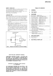
...SONY. 3 The "limit" indication is 0.75 V, so analog meters must not exceed 0.5 mA (500 microamperes.). Nearly all battery operated...operated AC voltmeter. TEST MODE 10 3. Printed Wiring Board - Schematic Diagram - MAIN Board (2/3), HEADPHONE Board 21 3-11. DISPLAY Board, POWER Board 25 3-15. DISPLAY Board, POWER Board 26 4. EXPLODED VIEWS 4-1. Schematic Diagram - Schematic Diagram - MAIN Board (3/3), ADCC Board, STANDBY Board 22 3-12. SAFETY-RELATED COMPONENT WARNING!! Follow the manufacturers' instructions... Panel Section 34 4-2. STR-K700 SAFETY CHECK-OUT After correcting...
...SONY. 3 The "limit" indication is 0.75 V, so analog meters must not exceed 0.5 mA (500 microamperes.). Nearly all battery operated...operated AC voltmeter. TEST MODE 10 3. Printed Wiring Board - Schematic Diagram - MAIN Board (2/3), HEADPHONE Board 21 3-11. DISPLAY Board, POWER Board 25 3-15. DISPLAY Board, POWER Board 26 4. EXPLODED VIEWS 4-1. Schematic Diagram - Schematic Diagram - MAIN Board (3/3), ADCC Board, STANDBY Board 22 3-12. SAFETY-RELATED COMPONENT WARNING!! Follow the manufacturers' instructions... Panel Section 34 4-2. STR-K700 SAFETY CHECK-OUT After correcting...


