Limited Warranty (US Only)
Page 1
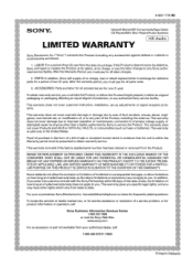
... number has been altered or removed from your convenience, Sony Electronics Inc. 4-557-172-02 General Stereo/Hifi Components/Tape Decks ® CD Players/Mini Disc Players/Audio Systems Hifi Audio LIMITED WARRANTY Sony Electronics Inc. ("Sony") warrants this Product is determined to be presented to obtain... of God, accident, misuse, abuse, negligence, commercial use, or modification of, or to any accessories) against defects in exchange for defective parts for one (1) year. This warranty does not cover Products sold AS IS or WITH ALL FAULTS, or consumables (such as follows: 1. ...
... number has been altered or removed from your convenience, Sony Electronics Inc. 4-557-172-02 General Stereo/Hifi Components/Tape Decks ® CD Players/Mini Disc Players/Audio Systems Hifi Audio LIMITED WARRANTY Sony Electronics Inc. ("Sony") warrants this Product is determined to be presented to obtain... of God, accident, misuse, abuse, negligence, commercial use, or modification of, or to any accessories) against defects in exchange for defective parts for one (1) year. This warranty does not cover Products sold AS IS or WITH ALL FAULTS, or consumables (such as follows: 1. ...
Marketing Specifications (HTDDW700 Home Theater System)
Page 2
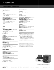
...222-7669 • www.sony.com Last Updated: 04/04/2006 Reproduction in whole or in part without notice. All other are subject to change without written permission is a trademark of their respective owners. HT-DDW700 Component Home Theater System Specifications Receiver Audio Audio Power Output: ... Power Requirements: AC 120V, 60 Hz Tuner Audio Tuner Frequency Range: AM: 530-1,710 kHz, FM: 87.5-108.0 MHz Station Preset(s): 10 AM, 20 FM Tuner Type: AM, FM Front Speaker Speaker Speaker Type: Enclosure- Features and specifications are trademarks of Dolby Laboratories. All rights...
...222-7669 • www.sony.com Last Updated: 04/04/2006 Reproduction in whole or in part without notice. All other are subject to change without written permission is a trademark of their respective owners. HT-DDW700 Component Home Theater System Specifications Receiver Audio Audio Power Output: ... Power Requirements: AC 120V, 60 Hz Tuner Audio Tuner Frequency Range: AM: 530-1,710 kHz, FM: 87.5-108.0 MHz Station Preset(s): 10 AM, 20 FM Tuner Type: AM, FM Front Speaker Speaker Speaker Type: Enclosure- Features and specifications are trademarks of Dolby Laboratories. All rights...

Operating Instructions
Page 2
... or shock hazard, do not expose this equipment. If this equipment does cause harmful interference to radio or television reception, which the receiver is intended to alert the user to the presence of uninsulated "dangerous voltage" within the product's enclosure that interference will not occur in... dispose of them correctly as vases, on , the user is no guarantee that may cause harmful interference to Part 15 of the following measures: Reorient or relocate the receiving antenna. CAUTION You are designed to comply with the limits for help. To prevent fire, do not cover the...
... or shock hazard, do not expose this equipment. If this equipment does cause harmful interference to radio or television reception, which the receiver is intended to alert the user to the presence of uninsulated "dangerous voltage" within the product's enclosure that interference will not occur in... dispose of them correctly as vases, on , the user is no guarantee that may cause harmful interference to Part 15 of the following measures: Reorient or relocate the receiving antenna. CAUTION You are designed to comply with the limits for help. To prevent fire, do not cover the...
Operating Instructions
Page 4
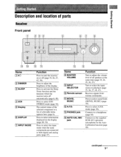
...-programmed sound field 39 Using only the front speakers and sub woofer (2CH STEREO) 42 Resetting sound fields to the initial settings 42 Tuner Operations Listening to FM/AM radio 43 Presetting radio stations 44 Other Operation Switching the audio input mode... 58 4us Table of Contents Getting Started Description and location of parts 5 1: Installing speakers 12 2: Connecting speakers 14 3: Connecting the audio/video components 15 4: Connecting the antennas 18 5: Preparing the receiver and the remote 19 6: Calibrating the appropriate settings automatically (AUTO...
...-programmed sound field 39 Using only the front speakers and sub woofer (2CH STEREO) 42 Resetting sound fields to the initial settings 42 Tuner Operations Listening to FM/AM radio 43 Presetting radio stations 44 Other Operation Switching the audio input mode... 58 4us Table of Contents Getting Started Description and location of parts 5 1: Installing speakers 12 2: Connecting speakers 14 3: Connecting the audio/video components 15 4: Connecting the antennas 18 5: Preparing the receiver and the remote 19 6: Calibrating the appropriate settings automatically (AUTO...
Operating Instructions
Page 5
..., 26, 27, 44, 47). Press to activate the Sleep Timer function and the duration which the receiver turns off (page 19, 26, 27, 42, 56). continued 51.1S papels Bugle° Description and location of parts Receiver Front panel -21 4 t 5 6 Name 1 ii(1) 121 DIMMER 3 SLEEP 4 2CH 5 Display... 6 DISPLAY 7 INPUT MODE Function Press to turn the receiver on the display (page 48, 54). Turn to select the input source to a headphone (page 40). Press to select 2CH STEREO mode (page 34). mode (page 38). Press to adjust the brightness of the display. Press...
..., 26, 27, 44, 47). Press to activate the Sleep Timer function and the duration which the receiver turns off (page 19, 26, 27, 42, 56). continued 51.1S papels Bugle° Description and location of parts Receiver Front panel -21 4 t 5 6 Name 1 ii(1) 121 DIMMER 3 SLEEP 4 2CH 5 Display... 6 DISPLAY 7 INPUT MODE Function Press to turn the receiver on the display (page 48, 54). Turn to select the input source to a headphone (page 40). Press to select 2CH STEREO mode (page 34). mode (page 38). Press to adjust the brightness of the display. Press...
Operating Instructions
Page 56
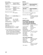
...consumption (during standby mode) 0.2 W Dimensions (w/h/d) (Approx.) 17 x 5 6/8 x 12 1/8 inches including projecting parts and controls Mass (Approx.) 16 lb 9 oz Speaker section Front speakers (SS-MSP700) Center speaker (SS-CNP700...Tone Gain levels ±6 dB, 1 dB step FM tuner section Tuning range Antenna Antenna terminals Intermediate frequency 87.5 - 108.0 MHz FM wire antenna 75 ohms, unbalanced 10.7 MHz AM ...procedure. Impedance: - After tuning in any AM station, turn off the receiver. Inputs (Analog) SA-CD/CD, DVD, VIDEO 1, 2 Sensitivity: 800 mV Impedance: 50 kohms...
...consumption (during standby mode) 0.2 W Dimensions (w/h/d) (Approx.) 17 x 5 6/8 x 12 1/8 inches including projecting parts and controls Mass (Approx.) 16 lb 9 oz Speaker section Front speakers (SS-MSP700) Center speaker (SS-CNP700...Tone Gain levels ±6 dB, 1 dB step FM tuner section Tuning range Antenna Antenna terminals Intermediate frequency 87.5 - 108.0 MHz FM wire antenna 75 ohms, unbalanced 10.7 MHz AM ...procedure. Impedance: - After tuning in any AM station, turn off the receiver. Inputs (Analog) SA-CD/CD, DVD, VIDEO 1, 2 Sensitivity: 800 mV Impedance: 50 kohms...
Operating Instructions
Page 63
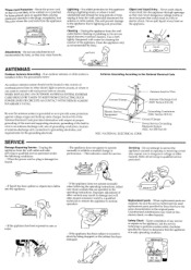
... hazards. Unauthorized substitutions may expose you to service the appliance yourself as specified by Sony that the appliance is left unattended and unused for the grounding electrode. All SETS RECEIVE OUR OK .SAFETY CHECK. Section 810 of the National Electrical Code provides information with... the following the operating instructions, adjust only those controls that are required, be sure the service technician has used replacement parts specified by Sony) to perform routine safety checks(as opening or removing covers may result in wire to an antenna discharge unit, size ...
... hazards. Unauthorized substitutions may expose you to service the appliance yourself as specified by Sony that the appliance is left unattended and unused for the grounding electrode. All SETS RECEIVE OUR OK .SAFETY CHECK. Section 810 of the National Electrical Code provides information with... the following the operating instructions, adjust only those controls that are required, be sure the service technician has used replacement parts specified by Sony) to perform routine safety checks(as opening or removing covers may result in wire to an antenna discharge unit, size ...
Operating Instructions
Page 65
... UNDER THIS WARRANTY IS THE EXCLUSIVE REMEDY OF THE CONSUMER. In addition, if you enter into a service contract with the Sony Partnership within the Warranty period must pay for all parts costs. 3. 4-557-173-02 SONY® General Stereo/Hifi Components/Tape Decks CD Players/Mini Disc Players/Audio Systems Hifi Audio LIMITED WARRANTY...
... UNDER THIS WARRANTY IS THE EXCLUSIVE REMEDY OF THE CONSUMER. In addition, if you enter into a service contract with the Sony Partnership within the Warranty period must pay for all parts costs. 3. 4-557-173-02 SONY® General Stereo/Hifi Components/Tape Decks CD Players/Mini Disc Players/Audio Systems Hifi Audio LIMITED WARRANTY...
Service Manual
Page 2
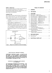
... replacement • Never reuse a disconnected chip component. • Notice that the minus side of area code AA only". Rear Panel - Parts No. MODEL IDENTIFICATION - UNLEADED SOLDER Boards requiring use only unleaded solder but the iron tip has to be set to about 40 °C...code of the receiver you purchased is best to use of unleaded solder are printed with the lead free mark due to their particular size) : LEAD FREE MARK Unleaded solder has the following characteristics. • Unleaded solder melts at a temperature about 350 °C. STR-K700 General Power ...
... replacement • Never reuse a disconnected chip component. • Notice that the minus side of area code AA only". Rear Panel - Parts No. MODEL IDENTIFICATION - UNLEADED SOLDER Boards requiring use only unleaded solder but the iron tip has to be set to about 40 °C...code of the receiver you purchased is best to use of unleaded solder are printed with the lead free mark due to their particular size) : LEAD FREE MARK Unleaded solder has the following characteristics. • Unleaded solder melts at a temperature about 350 °C. STR-K700 General Power ...
Service Manual
Page 3
... Schematic Diagram - MAIN Board (1/3 20 3-10. STANDBY Board 24 3-14. REPLACE THESE COMPONENTS WITH SONY PARTS WHOSE PART NUMBERS APPEAR AS SHOWN IN THIS MANUAL OR IN SUPPLEMENTS PUBLISHED BY SONY. DIGITAL Board (Side A) - ...... 14 3-4. Schematic Diagram - DIGITAL Board (2/3 17 3-7. Schematic ... are examples of three methods. 1. A) To Exposed Metal Parts on Set 0.15 µF 1.5 kΩ AC voltmeter (0.75 V) TABLE OF CONTENTS 1. DISPLAY Board, POWER Board 26 4. Printed Wiring Board - STR-K700 SAFETY CHECK-OUT After correcting the original service problem, perform...
... Schematic Diagram - MAIN Board (1/3 20 3-10. STANDBY Board 24 3-14. REPLACE THESE COMPONENTS WITH SONY PARTS WHOSE PART NUMBERS APPEAR AS SHOWN IN THIS MANUAL OR IN SUPPLEMENTS PUBLISHED BY SONY. DIGITAL Board (Side A) - ...... 14 3-4. Schematic Diagram - DIGITAL Board (2/3 17 3-7. Schematic ... are examples of three methods. 1. A) To Exposed Metal Parts on Set 0.15 µF 1.5 kΩ AC voltmeter (0.75 V) TABLE OF CONTENTS 1. DISPLAY Board, POWER Board 26 4. Printed Wiring Board - STR-K700 SAFETY CHECK-OUT After correcting the original service problem, perform...
Service Manual
Page 11
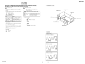
... AND SCHEMATIC DIAGRAMS. (In addition to ground un- Parts on the pattern face side seen from the side which enables seeing. C Q These are omitted. • Circuit Boards Location POWER board STANDBY board MAIN board STR-K700 ADCC board HEADPHONE board DISPLAY board DIGITAL board •...40 ns/DIV 2 IC1101 id (X1) 3.4 Vp-p 41.6 ns 1 V/DIV, 20 ns/DIV 3 IC1301 ws (XIN) 4.2 Vp-p STR-K700 81 ns 1 V/DIV, 40 ns/DIV 11 11 4.4 Vp-p F : FM J : ANALOG c : DIGITAL • Indication of transistor. Note: Les composants identifiés par une marque 0 sont critiques pour la s&#...
... AND SCHEMATIC DIAGRAMS. (In addition to ground un- Parts on the pattern face side seen from the side which enables seeing. C Q These are omitted. • Circuit Boards Location POWER board STANDBY board MAIN board STR-K700 ADCC board HEADPHONE board DISPLAY board DIGITAL board •...40 ns/DIV 2 IC1101 id (X1) 3.4 Vp-p 41.6 ns 1 V/DIV, 20 ns/DIV 3 IC1301 ws (XIN) 4.2 Vp-p STR-K700 81 ns 1 V/DIV, 40 ns/DIV 11 11 4.4 Vp-p F : FM J : ANALOG c : DIGITAL • Indication of transistor. Note: Les composants identifiés par une marque 0 sont critiques pour la s&#...

Service Manual
Page 34
... SECTION The components identified by mark 0 or dotted line with RV102 1 3 4 #1 8 chassis section Ref. No. 6 7 8 9 Part No. Replace only with no reference number in the exploded views are not supplied. • Items marked "*" are not stocked since they may have... be anticipated when ordering these items. • Abbreviation CND : Canadian model. 4-1. No. 1 2 3 3 4 Part No. STR-K700 SECTION 4 EXPLODED VIEWS NOTE: • -XX and -X mean standardized parts, so they are seldom required for safety. Description A-1156-368-A DISPLAY BOARD, COMPLETE 1-829-004-11 WIRE (FLAT ...
... SECTION The components identified by mark 0 or dotted line with RV102 1 3 4 #1 8 chassis section Ref. No. 6 7 8 9 Part No. Replace only with no reference number in the exploded views are not supplied. • Items marked "*" are not stocked since they may have... be anticipated when ordering these items. • Abbreviation CND : Canadian model. 4-1. No. 1 2 3 3 4 Part No. STR-K700 SECTION 4 EXPLODED VIEWS NOTE: • -XX and -X mean standardized parts, so they are seldom required for safety. Description A-1156-368-A DISPLAY BOARD, COMPLETE 1-829-004-11 WIRE (FLAT ...

Service Manual
Page 35
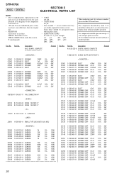
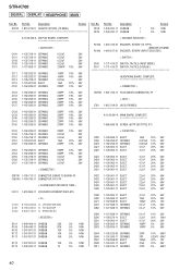
No. 51 52 53 54 55 * 56 0 57 58 59 60 61 0 F901 Q503 Q504 Part No. Q553 Q554 Q603 Q604 Q653 Q654 Q703 Q704 Q753 Q754 0 T901 TN1 #1 Part No. No. Description 3-701-748-00 CLAMP 4-249-675-01 +BV SUMITITE S 4X6 ROUND A-1156-365-A STANDBY BOARD, COMPLETE 3-077-331-21 +BV3...-01 IC MP1620-OPY-MK 1-443-909-11 POWER TRANSFORMER (MAIN) 1-693-675-21 TUNER 7-685-646-79 SCREW +BVTP 3X8 TYPE2 IT-3 Remark 35 STR-K700 4-2. CHASSIS SECTION 51 52 54 not supplied #1 not supplied Q554 Q654 Q553 Q604 Q503 Q504 Q754 55 Q653 Q603 Q753 Q703 Q704 54 #1 54 F901...
No. 51 52 53 54 55 * 56 0 57 58 59 60 61 0 F901 Q503 Q504 Part No. Q553 Q554 Q603 Q604 Q653 Q654 Q703 Q704 Q753 Q754 0 T901 TN1 #1 Part No. No. Description 3-701-748-00 CLAMP 4-249-675-01 +BV SUMITITE S 4X6 ROUND A-1156-365-A STANDBY BOARD, COMPLETE 3-077-331-21 +BV3...-01 IC MP1620-OPY-MK 1-443-909-11 POWER TRANSFORMER (MAIN) 1-693-675-21 TUNER 7-685-646-79 SCREW +BVTP 3X8 TYPE2 IT-3 Remark 35 STR-K700 4-2. CHASSIS SECTION 51 52 54 not supplied #1 not supplied Q554 Q654 Q553 Q604 Q503 Q504 Q754 55 Q653 Q603 Q753 Q703 Q704 54 #1 54 F901...
Service Manual
Page 36
... components identified by reference number, please include the board name. No. uPA. . : µPA. . Part No. STR-K700 ADCC DIGITAL SECTION 5 ELECTRICAL PARTS LIST NOTE: • Due to standardization, replacements in the parts list may have some difference from the parts specified in the diagrams or the components used on the set. • -XX and -X mean...
... components identified by reference number, please include the board name. No. uPA. . : µPA. . Part No. STR-K700 ADCC DIGITAL SECTION 5 ELECTRICAL PARTS LIST NOTE: • Due to standardization, replacements in the parts list may have some difference from the parts specified in the diagrams or the components used on the set. • -XX and -X mean...
Service Manual
Page 37
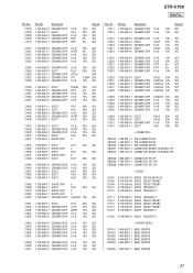
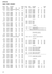
C1305 C1306 C1308 C1309 C1310 Part No. No. C1511 C1513 Part No. Description 1-100-566-91 CERAMIC CHIP 1-126-947-11 ELECT 1-100-566-91 CERAMIC CHIP 1-162-918-11 CERAMIC CHIP 1-162-918-11 CERAMIC ...-566-91 CERAMIC CHIP 1-100-566-91 CERAMIC CHIP 1-100-566-91 CERAMIC CHIP 0.1uF 0.1uF 0.1uF 10% 25V 10% 25V 10% 25V Ref. No. STR-K700 DIGITAL Ref. Description 1-100-566-91 CERAMIC CHIP 1-100-566-91 CERAMIC CHIP 0.1uF 0.1uF Remark 10% 25V 10% 25V C1514 C1515 C1516 C1517 C1518...
C1305 C1306 C1308 C1309 C1310 Part No. No. C1511 C1513 Part No. Description 1-100-566-91 CERAMIC CHIP 1-126-947-11 ELECT 1-100-566-91 CERAMIC CHIP 1-162-918-11 CERAMIC CHIP 1-162-918-11 CERAMIC ...-566-91 CERAMIC CHIP 1-100-566-91 CERAMIC CHIP 1-100-566-91 CERAMIC CHIP 0.1uF 0.1uF 0.1uF 10% 25V 10% 25V 10% 25V Ref. No. STR-K700 DIGITAL Ref. Description 1-100-566-91 CERAMIC CHIP 1-100-566-91 CERAMIC CHIP 0.1uF 0.1uF Remark 10% 25V 10% 25V C1514 C1515 C1516 C1517 C1518...
Service Manual
Page 40
Part No. STR-K700 DIGITAL DISPLAY HEADPHONE MAIN Ref. Part No. Description X1502 1-813-276-21 QUARTZ CRYSTAL (13.9MHz) R198 1-249-381-11 CARBON 1 R199 1-249-381-11 CARBON 1 Remark 5% 1/4W 5% 1/4W A-1156-368-A ...
Part No. STR-K700 DIGITAL DISPLAY HEADPHONE MAIN Ref. Part No. Description X1502 1-813-276-21 QUARTZ CRYSTAL (13.9MHz) R198 1-249-381-11 CARBON 1 R199 1-249-381-11 CARBON 1 Remark 5% 1/4W 5% 1/4W A-1156-368-A ...
Service Manual
Page 44
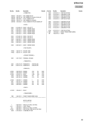
...-11 ELECT 1-126-943-11 ELECT 1-126-942-61 ELECT 3300uF 20% 16V 2200uF 20% 25V 1000uF 20% 25V 44 No. 0 R708 0 R709 0 R710 R711 Part No. Description 1-249-405-11 CARBON 100 5% 1-249-405-11 CARBON 100 5% 1-234-182-11 ENCAPSULATED COMPONENT 1-247-847-91 CARBON 4.7K 5% 0 R712 R713 R714... 1/4W 1/4W 1/4W 1/4W 1/4W 1/4W 1/4W 1/4W 1/4W 1/4W 1/4W 1/4W 1/4W 1/6W 1/6W 1/4W 1/4W 1/4W 1/4W 1/4W 1/4W 1/4W 1/4W 1/4W Ref. Part No. No. STR-K700 MAIN POWER STANDBY Ref.
...-11 ELECT 1-126-943-11 ELECT 1-126-942-61 ELECT 3300uF 20% 16V 2200uF 20% 25V 1000uF 20% 25V 44 No. 0 R708 0 R709 0 R710 R711 Part No. Description 1-249-405-11 CARBON 100 5% 1-249-405-11 CARBON 100 5% 1-234-182-11 ENCAPSULATED COMPONENT 1-247-847-91 CARBON 4.7K 5% 0 R712 R713 R714... 1/4W 1/4W 1/4W 1/4W 1/4W 1/4W 1/4W 1/4W 1/4W 1/4W 1/4W 1/4W 1/4W 1/6W 1/6W 1/4W 1/4W 1/4W 1/4W 1/4W 1/4W 1/4W 1/4W 1/4W Ref. Part No. No. STR-K700 MAIN POWER STANDBY Ref.
Service Manual
Page 45
...-452-11 FUSE, GLASS TUBE (DIA. 5) (4A/125V) 6-702-390-01 IC MN2488-OPY-MK Remark 45 STR-K700 STANDBY Ref. No. Q504 Q553 Q554 Q603 Q604 Q653 Q654 Q703 Q704 Q753 Q754 0 T901 TN1 Part No. Part No. Description < CONNECTOR > Remark CNP801 1-784-922-11 PIN, CONNECTOR 5P CNP900 1-564-321-00 PIN...
...-452-11 FUSE, GLASS TUBE (DIA. 5) (4A/125V) 6-702-390-01 IC MN2488-OPY-MK Remark 45 STR-K700 STANDBY Ref. No. Q504 Q553 Q554 Q603 Q604 Q653 Q654 Q703 Q704 Q753 Q754 0 T901 TN1 Part No. Part No. Description < CONNECTOR > Remark CNP801 1-784-922-11 PIN, CONNECTOR 5P CNP900 1-564-321-00 PIN...


