Marketing Specifications (HTDDW700 Home Theater System)
Page 1
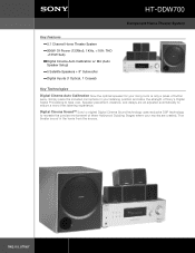
HT-DDW700 Component Home Theater System Key Features 5.1 Channel Home Theater System 800W Of Power (133Wx5, 1KHz,
HT-DDW700 Component Home Theater System Key Features 5.1 Channel Home Theater System 800W Of Power (133Wx5, 1KHz,
Marketing Specifications (HTDDW700 Home Theater System)
Page 2
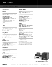
...-7669 • www.sony.com Last Updated: 04/04/2006 All rights reserved. HT-DDW700 Component Home Theater System Specifications Receiver Audio Audio Power Output: 800W (133w x 5 + 135w (1KHz, 10% THD)) Inputs and Outputs Analog Audio Input(s): 4 (Rear) Antenna Terminal(s): Yes (FM 75ohms, AM Loop) Coaxial Audio Digital Input(s): 1 (Rear) Optical Audio Input(s): 1 (Rear...
...-7669 • www.sony.com Last Updated: 04/04/2006 All rights reserved. HT-DDW700 Component Home Theater System Specifications Receiver Audio Audio Power Output: 800W (133w x 5 + 135w (1KHz, 10% THD)) Inputs and Outputs Analog Audio Input(s): 4 (Rear) Antenna Terminal(s): Yes (FM 75ohms, AM Loop) Coaxial Audio Digital Input(s): 1 (Rear) Optical Audio Input(s): 1 (Rear...
Operating Instructions
Page 6
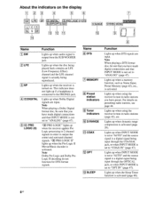
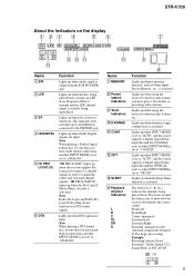
...is connected to "OPT IN" (page 47). Lights up when the disc being input through the OPTICAL jack, or when INPUT MODE is turned on presetting radio stations, see page 44. "DO ...(page 29). Lights up when dynamic range compression is activated. Lights up when using the receiver to output the center and surround channel signals. Note Dolby Pro Logic and Dolby Pro Logic...47). About the indicators on the display 1 4 15 LFE L C R SL SR 14 SLEEP roTTCOAX 113 MEMORY D.RANGEI STEREO MON 10 191 ••• Name 1 SW 2 LFE 3 SP 4 DODIGITAL 5 DO PRO LOGIC (II) ...
...is connected to "OPT IN" (page 47). Lights up when the disc being input through the OPTICAL jack, or when INPUT MODE is turned on presetting radio stations, see page 44. "DO ...(page 29). Lights up when dynamic range compression is activated. Lights up when using the receiver to output the center and surround channel signals. Note Dolby Pro Logic and Dolby Pro Logic...47). About the indicators on the display 1 4 15 LFE L C R SL SR 14 SLEEP roTTCOAX 113 MEMORY D.RANGEI STEREO MON 10 191 ••• Name 1 SW 2 LFE 3 SP 4 DODIGITAL 5 DO PRO LOGIC (II) ...
Operating Instructions
Page 8
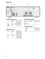
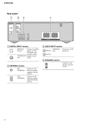
Bus Rear panel [ 1 t" C DIGITAL INPUT section OPTICAL Connects to the speakers and sub woofer (page 14). Connects to the AM loop antenna supplied with this receiver (page 18). 3 AUDIO INPUT section AUDIO IN O White (L) jack O Red (R) Connects to a CD player, etc. (page 16). 141 SPEAKER section Connects to a DVD IN jack player, etc. The COAXIAL jack provides a better COAXIAL IN quality of loud jack sound (page 17). 2 ANTENNA section FM 0 ANTENNA AM ANTENNA Connects to the FM wire antenna supplied with this receiver (page 18).
Bus Rear panel [ 1 t" C DIGITAL INPUT section OPTICAL Connects to the speakers and sub woofer (page 14). Connects to the AM loop antenna supplied with this receiver (page 18). 3 AUDIO INPUT section AUDIO IN O White (L) jack O Red (R) Connects to a CD player, etc. (page 16). 141 SPEAKER section Connects to a DVD IN jack player, etc. The COAXIAL jack provides a better COAXIAL IN quality of loud jack sound (page 17). 2 ANTENNA section FM 0 ANTENNA AM ANTENNA Connects to the FM wire antenna supplied with this receiver (page 18).

Operating Instructions
Page 15
Select the connection according to the jacks of your components to this receiver. Refer to be connected The sound quality depends on the connecting jack. papels BumeD 3: Connecting the audio/video components How to hook up your components This section describes how to hook up all your components, proceed to "4: Connecting the antennas" (page 18). Audio input jack to the illustration that follows. COAXIA IN OPTICAL IN Digital OAURDINIO Analog High quality sound 1 5US After hooking up your components.
Select the connection according to the jacks of your components to this receiver. Refer to be connected The sound quality depends on the connecting jack. papels BumeD 3: Connecting the audio/video components How to hook up your components This section describes how to hook up all your components, proceed to "4: Connecting the antennas" (page 18). Audio input jack to the illustration that follows. COAXIA IN OPTICAL IN Digital OAURDINIO Analog High quality sound 1 5US After hooking up your components.
Operating Instructions
Page 17
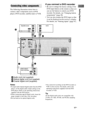
... setting on the DVD player. VCR J. Satellite tuner 86 0 If you can be displayed on the DVD recorder or VCR via this receiver. papels Bu!nap Connecting video components The following illustration shows how to control your DVD recorder. For details, refer to the operating instructions ... cords, insert the plugs straight in until they click into place. • Do not bend or tie optical digital cords. • You cannot do recording on the receiver's display. Refer to the operating instructions supplied with 32 kHz, 44.1 kHz, 48 kHz, and 96 kHz sampling frequencies. 17us For...
... setting on the DVD player. VCR J. Satellite tuner 86 0 If you can be displayed on the DVD recorder or VCR via this receiver. papels Bu!nap Connecting video components The following illustration shows how to control your DVD recorder. For details, refer to the operating instructions ... cords, insert the plugs straight in until they click into place. • Do not bend or tie optical digital cords. • You cannot do recording on the receiver's display. Refer to the operating instructions supplied with 32 kHz, 44.1 kHz, 48 kHz, and 96 kHz sampling frequencies. 17us For...
Operating Instructions
Page 47
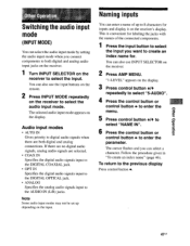
... control button + to enter the menu. 5 Press control button +1+ to the AUDIO IN (L/R) jacks. The selected audio input mode appears on the receiver to create an index name for labeling the jacks with the names of up depending on the input. If there are no digital audio signals... COAX IN Specifies the digital audio signals input to the DIGITAL COAXIAL jack. • OPT IN Specifies the digital audio signals input to the DIGITAL OPTICAL jack. • ANALOG Specifies the analog audio signals input to select "NAME IN". 6 Press the control button or control button . Naming inputs ...
... control button + to enter the menu. 5 Press control button +1+ to the AUDIO IN (L/R) jacks. The selected audio input mode appears on the receiver to create an index name for labeling the jacks with the names of up depending on the input. If there are no digital audio signals... COAX IN Specifies the digital audio signals input to the DIGITAL COAXIAL jack. • OPT IN Specifies the digital audio signals input to the DIGITAL OPTICAL jack. • ANALOG Specifies the analog audio signals input to select "NAME IN". 6 Press the control button or control button . Naming inputs ...
Operating Instructions
Page 53
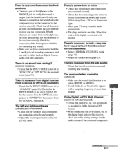
... headphones, the front speaker may not be obtained. • Make sure the sound field function is not set to the digital input jacks of this receiver, check the audio setting (settings for the audio output) of the connected component. to "COAX IN" or "OPT IN" for the sources from ... cloth slightly moistened with a sampling frequency of more than 48 kHz. The surround effect cannot be connected to the receiver correctly. There is no sound from digital sources (from COAXIAL or OPTICAL input jack). • Check that the INPUT MODE is not set to verify that the INPUT MODE is on both...
... headphones, the front speaker may not be obtained. • Make sure the sound field function is not set to the digital input jacks of this receiver, check the audio setting (settings for the audio output) of the connected component. to "COAX IN" or "OPT IN" for the sources from ... cloth slightly moistened with a sampling frequency of more than 48 kHz. The surround effect cannot be connected to the receiver correctly. There is no sound from digital sources (from COAXIAL or OPTICAL input jack). • Check that the INPUT MODE is not set to verify that the INPUT MODE is on both...
Operating Instructions
Page 56
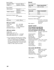
...20,000 Hz Tone Gain levels ±6 dB, 1 dB step FM tuner section Tuning range Antenna Antenna terminals Intermediate frequency 87.5 - 108.0 MHz FM wire antenna 75 ohms, unbalanced 10.7 MHz AM tuner section Tuning range... Models of area code U, CA With 10-kHz tuning scale: 530 - 1,710 kHz3) With 9-kHz tuning scale: 531 - 1,710 kHz3) 3) You can change the tuning scale. After tuning in any AM station, turn off the receiver...: 800 mV Impedance: 50 kohms Inputs (Digital) DVD (Coaxial) VIDEO 2 (Optical) Sensitivity: -
...20,000 Hz Tone Gain levels ±6 dB, 1 dB step FM tuner section Tuning range Antenna Antenna terminals Intermediate frequency 87.5 - 108.0 MHz FM wire antenna 75 ohms, unbalanced 10.7 MHz AM tuner section Tuning range... Models of area code U, CA With 10-kHz tuning scale: 530 - 1,710 kHz3) With 9-kHz tuning scale: 531 - 1,710 kHz3) 3) You can change the tuning scale. After tuning in any AM station, turn off the receiver...: 800 mV Impedance: 50 kohms Inputs (Digital) DVD (Coaxial) VIDEO 2 (Optical) Sensitivity: -
Service Manual
Page 1
...2 (Optical) Sensitivity: - While holding down DIMMER, press ?/1. All preset stations will be no more than 0.7% total harmonic distortion from 250 milliwatts to rated output. Impedance: 75 ohms Sensitivity: - FM STEREO FM-AM RECEIVER 9-887-073-01 2006A1678-1 © 2006.01 Sony Corporation Home Audio Division Published by Sony Techno Create.... rated 85 watts per channel minimum RMS power, with no sound output. SERVICE MANUAL Ver. 1.0 2006.01 STR-K700 US Model Canadian Model • STR-K700 is the tuner and the amplifier section in any AM station, turn off the receiver.
...2 (Optical) Sensitivity: - While holding down DIMMER, press ?/1. All preset stations will be no more than 0.7% total harmonic distortion from 250 milliwatts to rated output. Impedance: 75 ohms Sensitivity: - FM STEREO FM-AM RECEIVER 9-887-073-01 2006A1678-1 © 2006.01 Sony Corporation Home Audio Division Published by Sony Techno Create.... rated 85 watts per channel minimum RMS power, with no sound output. SERVICE MANUAL Ver. 1.0 2006.01 STR-K700 US Model Canadian Model • STR-K700 is the tuner and the amplifier section in any AM station, turn off the receiver.
Service Manual
Page 5
... II DTS SLEEP OPT COAX LCR SL S SR qd qs qa MEMORY D.RANGE STEREO MONO 0 9 qf 8 Name Function Name Function A SW B LFE C SP...input through the OPTICAL jack, or when INPUT MODE is activated. DIGITAL ; Lights up when using the receiver to "ANALOG". ...receiver downmixes the source sound. Lights up when DTS signals are input. Front Left Front Right Center (monaural) Surround Left Surround Right Surround (monaural or the surround components obtained by Pro Logic processing) Example: Recording format (Front/ Surround): Dolby Digital 3/2.1 Sound Field: A.F.D. STR-K700...
... II DTS SLEEP OPT COAX LCR SL S SR qd qs qa MEMORY D.RANGE STEREO MONO 0 9 qf 8 Name Function Name Function A SW B LFE C SP...input through the OPTICAL jack, or when INPUT MODE is activated. DIGITAL ; Lights up when using the receiver to "ANALOG". ...receiver downmixes the source sound. Lights up when DTS signals are input. Front Left Front Right Center (monaural) Surround Left Surround Right Surround (monaural or the surround components obtained by Pro Logic processing) Example: Recording format (Front/ Surround): Dolby Digital 3/2.1 Sound Field: A.F.D. STR-K700...
Service Manual
Page 6
...STR-K700 Rear panel 1 23 4 DIGITAL OPTICAL VIDEO 2 IN DVD IN COAXIAL ANTENNA AM L L R R AUDIO IN AUDIO IN AUDIO IN S DVD VIDEO 2 L R AUDIO IN VIDEO 1 RL RL + ++ + SUB WOOFER RL SURROUND SPEAKERS CENTER RL FRONT A DIGITAL INPUT section OPTICAL Connects to the FM wire antenna supplied with this receiver... . Connects to the AM loop antenna supplied with this receiver . B ANTENNA section FM ANTENNA AM ANTENNA Connects to a DVD IN jack ...
...STR-K700 Rear panel 1 23 4 DIGITAL OPTICAL VIDEO 2 IN DVD IN COAXIAL ANTENNA AM L L R R AUDIO IN AUDIO IN AUDIO IN S DVD VIDEO 2 L R AUDIO IN VIDEO 1 RL RL + ++ + SUB WOOFER RL SURROUND SPEAKERS CENTER RL FRONT A DIGITAL INPUT section OPTICAL Connects to the FM wire antenna supplied with this receiver... . Connects to the AM loop antenna supplied with this receiver . B ANTENNA section FM ANTENNA AM ANTENNA Connects to a DVD IN jack ...


