Operating Instructions
Page 2
... the receiving antenna. KDL-26M4000 KDL-32M4000 KDL-37M4000 KDL-40M4000 Sony Wall-Mount Bracket Model No. SU-WL100 SU-WL500 Sony TV Stand Model No. - - Be sure to subcontract the installation to Sony dealer or licensed contractors and pay adequate attention to direct illumination or direct sunlight. Note This television includes a QAM demodulator which can radiate radio frequency energy and, if not installed and used in a residential installation. This TV incorporates...
... the receiving antenna. KDL-26M4000 KDL-32M4000 KDL-37M4000 KDL-40M4000 Sony Wall-Mount Bracket Model No. SU-WL100 SU-WL500 Sony TV Stand Model No. - - Be sure to subcontract the installation to Sony dealer or licensed contractors and pay adequate attention to direct illumination or direct sunlight. Note This television includes a QAM demodulator which can radiate radio frequency energy and, if not installed and used in a residential installation. This TV incorporates...
Operating Instructions
Page 3
...Menu 28 Using the Picture Menu 30 Using the Sound Menu 31 Using the Screen Menu 32 Using the Channel Menu 33 Using the Parental Lock 34 Using the Setup Menu 37 Other Information Troubleshooting 39 Specifications 42 Index 43 Quick Setup Guide (separate volume) Provides a variety of BRAVIA® The Four Steps to Attach the Table-Top Stand 5 Securing the TV 6 Bundling the Connecting Cables 8 Preparation for Wall-Mounting 8 Installing the Wall-Mount Bracket 9 When Installing the TV Against a Wall or Enclosed Area 11 2. Locating Inputs and Outputs 12 Side Panel 12 Rear Panel...
...Menu 28 Using the Picture Menu 30 Using the Sound Menu 31 Using the Screen Menu 32 Using the Channel Menu 33 Using the Parental Lock 34 Using the Setup Menu 37 Other Information Troubleshooting 39 Specifications 42 Index 43 Quick Setup Guide (separate volume) Provides a variety of BRAVIA® The Four Steps to Attach the Table-Top Stand 5 Securing the TV 6 Bundling the Connecting Cables 8 Preparation for Wall-Mounting 8 Installing the Wall-Mount Bracket 9 When Installing the TV Against a Wall or Enclosed Area 11 2. Locating Inputs and Outputs 12 Side Panel 12 Rear Panel...
Operating Instructions
Page 6
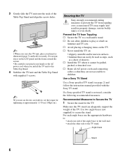
... TV sets. s Route all AC power cords and connecting cables so that can adequately support the weight of the TV. Recommended Measures to Secure the TV 1 Secure the stand for tightening at approximately 1.5 N·m {15Kgf·cm}. For each angle brace use an electric screwdriver, set the torque for the TV. 3 Gently slide the TV unit onto the neck of the Table-Top Stand and align the screws...
... TV sets. s Route all AC power cords and connecting cables so that can adequately support the weight of the TV. Recommended Measures to Secure the TV 1 Secure the stand for tightening at approximately 1.5 N·m {15Kgf·cm}. For each angle brace use an electric screwdriver, set the torque for the TV. 3 Gently slide the TV unit onto the neck of the Table-Top Stand and align the screws...
Operating Instructions
Page 8
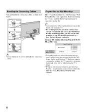
... the instruction guide provided by the WallMount Bracket model for Wall-Mounting This TV can bundle the connecting cables as illustrated below. ~ • Do not bundle the AC power cord with the following WALL-MOUNT BRACKET only. Preparation for your TV and the wallmounting of the wall for withstanding the TV's weight. • Be sure to store the removed screws and Table-Top Stand in installing this TV, especially to the instructions on a wall by a Sony dealer...
... the instruction guide provided by the WallMount Bracket model for Wall-Mounting This TV can bundle the connecting cables as illustrated below. ~ • Do not bundle the AC power cord with the following WALL-MOUNT BRACKET only. Preparation for your TV and the wallmounting of the wall for withstanding the TV's weight. • Be sure to store the removed screws and Table-Top Stand in installing this TV, especially to the instructions on a wall by a Sony dealer...
Operating Instructions
Page 9
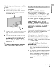
... weight of the TV. The wall must be wall-mounted using a Wall-Mount Bracket (sold separately). Getting Started Follow the simple steps below . See table on page 8 showing the WallMount Bracket model appropriate for all the cables from the TV. 2 Remove the 3 screws from the TV. For more details refer to Install the WallMount Bracket and also the Instruction Guide provided by a Sony dealer or a licensed contractor. Installing the Wall-Mount Bracket To Customers Your KDL-26M4000/KDL...
... weight of the TV. The wall must be wall-mounted using a Wall-Mount Bracket (sold separately). Getting Started Follow the simple steps below . See table on page 8 showing the WallMount Bracket model appropriate for all the cables from the TV. 2 Remove the 3 screws from the TV. For more details refer to Install the WallMount Bracket and also the Instruction Guide provided by a Sony dealer or a licensed contractor. Installing the Wall-Mount Bracket To Customers Your KDL-26M4000/KDL...
Operating Instructions
Page 10
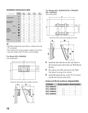
... on the wall For Model KDL-26M4000 Unit: inches (mm) Center line of the TV that you are installing. a f, j c f, j b e, g b 10 Refer to support at least four times the weight of the screen when installed on the wall 3 Install the Base Bracket on the TV. Screw and Hook locations diagram/table TV Model KDL-26M4000 KDL-32M4000 KDL-37M4000 KDL-40M4000 Screw location Hook location - See Screw and Hook locations table below. Installation dimensions table Unit: inches (mm) TV Model KDL26M4000 KDL32M4000 KDL37M4000 KDL40M4000 TV dimensions Screen center dimensions A 26...
... on the wall For Model KDL-26M4000 Unit: inches (mm) Center line of the TV that you are installing. a f, j c f, j b e, g b 10 Refer to support at least four times the weight of the screen when installed on the wall 3 Install the Base Bracket on the TV. Screw and Hook locations diagram/table TV Model KDL-26M4000 KDL-32M4000 KDL-37M4000 KDL-40M4000 Screw location Hook location - See Screw and Hook locations table below. Installation dimensions table Unit: inches (mm) TV Model KDL26M4000 KDL32M4000 KDL37M4000 KDL40M4000 TV dimensions Screen center dimensions A 26...
Operating Instructions
Page 12
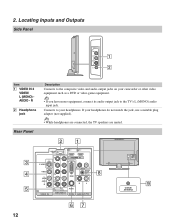
...Description Connects to the TV's L (MONO) audio input jack. Locating Inputs and Outputs Side Panel VIDEO IN 2 VIDEO L (MONO) AUDIO R 1 2 Item 1 VIDEO IN 2 VIDEO/ L (MONO) AUDIO - Rear Panel 21 3 4 5 SERVICE ONLY 1 2 Y IN S VIDEO VIDEO L (MONO) AUDIO R 1 VIDEO IN P B P R L AUDIO R R RGB AUDIO L DIGITAL AUDIO OUT (COAXIAL) R L 1 2 COMPONENT IN (1080i/720p/480p/480i) AUDIO PC IN AUDIO OUT (FIX) 8 CABLE/ ANTENNA 9 67 12 If your headphones do not match the jack, use a suitable plug adapter (not supplied). • While headphones are connected, the TV speakers are...
...Description Connects to the TV's L (MONO) audio input jack. Locating Inputs and Outputs Side Panel VIDEO IN 2 VIDEO L (MONO) AUDIO R 1 2 Item 1 VIDEO IN 2 VIDEO/ L (MONO) AUDIO - Rear Panel 21 3 4 5 SERVICE ONLY 1 2 Y IN S VIDEO VIDEO L (MONO) AUDIO R 1 VIDEO IN P B P R L AUDIO R R RGB AUDIO L DIGITAL AUDIO OUT (COAXIAL) R L 1 2 COMPONENT IN (1080i/720p/480p/480i) AUDIO PC IN AUDIO OUT (FIX) 8 CABLE/ ANTENNA 9 67 12 If your headphones do not match the jack, use a suitable plug adapter (not supplied). • While headphones are connected, the TV speakers are...
Operating Instructions
Page 13
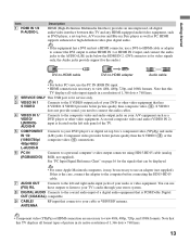
... format types of picture in a resolution of 1,366 dots × 768 lines. 13 Note that this TV displays all video input signals in its native resolution of 1,366 dots × 768 lines. 2 SERVICE ONLY This USB port is PCM/Dolby Digital OUT (COAXIAL) compatible. 9 CABLE/ ANTENNA RF input that connects to your DVD or other video equipment. S VIDEO does not provide sound, you need to connect the audio cables. 4 VIDEO IN 1/ VIDEO/ L(MONO)AUDIO-R Connects to a personal computer's video output connector using HD15-HD15 cable (analog...
... format types of picture in a resolution of 1,366 dots × 768 lines. 13 Note that this TV displays all video input signals in its native resolution of 1,366 dots × 768 lines. 2 SERVICE ONLY This USB port is PCM/Dolby Digital OUT (COAXIAL) compatible. 9 CABLE/ ANTENNA RF input that connects to your DVD or other video equipment. S VIDEO does not provide sound, you need to connect the audio cables. 4 VIDEO IN 1/ VIDEO/ L(MONO)AUDIO-R Connects to a personal computer's video output connector using HD15-HD15 cable (analog...

Operating Instructions
Page 14
... the HDMI or component video (with HDMI Connection HDMI cable CATV/ Satellite antenna cable HD cable box/HD satellite box 14 SERVICE ONLY 1 2 Y IN S VIDEO VIDEO L (MONO) AUDIO R 1 VIDEO IN PB PR L AUDIO R R RGB AUDIO L DIGITAL AUDIO OUT (COAXIAL) R L 1 2 COMPONENT IN (1080i/720p/480p/480i) AUDIO PC IN AUDIO OUT (FIX) Rear of your TV. For the best possible picture, connect these components to receive optimum picture quality. A 300-ohm twin lead cable can also enjoy high-definition programming by radio frequency interference, resulting in Channel menu...
... the HDMI or component video (with HDMI Connection HDMI cable CATV/ Satellite antenna cable HD cable box/HD satellite box 14 SERVICE ONLY 1 2 Y IN S VIDEO VIDEO L (MONO) AUDIO R 1 VIDEO IN PB PR L AUDIO R R RGB AUDIO L DIGITAL AUDIO OUT (COAXIAL) R L 1 2 COMPONENT IN (1080i/720p/480p/480i) AUDIO PC IN AUDIO OUT (FIX) Rear of your TV. For the best possible picture, connect these components to receive optimum picture quality. A 300-ohm twin lead cable can also enjoy high-definition programming by radio frequency interference, resulting in Channel menu...
Operating Instructions
Page 16
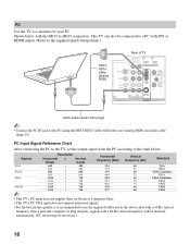
... to HD15 connection. In plug and play, signals with a 60 Hz vertical frequency will be detected automatically. (PC reboot may be connected to a PC with DVI or HDMI output. (Refer to the supplied Quick Setup Guide.) HD15HD15 cable (analog RGB) Rear of TV SERVICE ONLY Y 1 2 IN S VIDEO VIDEO L (MONO) AUDIO R 1 VIDEO IN PB PR L AUDIO R R RGB AUDIO L DIGITAL AUDIO OUT (COAXIAL) R L 1 2 COMPONENT IN (1080i/720p/480p/480i) AUDIO PC IN AUDIO OUT (FIX) Audio cable (stereo mini plugs) ~ • Connect the PC...
... to HD15 connection. In plug and play, signals with a 60 Hz vertical frequency will be detected automatically. (PC reboot may be connected to a PC with DVI or HDMI output. (Refer to the supplied Quick Setup Guide.) HD15HD15 cable (analog RGB) Rear of TV SERVICE ONLY Y 1 2 IN S VIDEO VIDEO L (MONO) AUDIO R 1 VIDEO IN PB PR L AUDIO R R RGB AUDIO L DIGITAL AUDIO OUT (COAXIAL) R L 1 2 COMPONENT IN (1080i/720p/480p/480i) AUDIO PC IN AUDIO OUT (FIX) Audio cable (stereo mini plugs) ~ • Connect the PC...

Operating Instructions
Page 18
... Channel menu as described on the screen to turn on the TV. The Initial Setup screen appears. If you have cable and antenna available, please connect cable first. • IMPORTANT: You must perform Auto Program after cable or antenna is connected. To run Auto Program at a later time ❑ Use the Auto Program feature at this time, you do it later by selecting the Auto Program option in your TV for available channels from signal source directly connected to the TV's CABLE/ANTENNA input...
... Channel menu as described on the screen to turn on the TV. The Initial Setup screen appears. If you have cable and antenna available, please connect cable first. • IMPORTANT: You must perform Auto Program after cable or antenna is connected. To run Auto Program at a later time ❑ Use the Auto Program feature at this time, you do it later by selecting the Auto Program option in your TV for available channels from signal source directly connected to the TV's CABLE/ANTENNA input...

Operating Instructions
Page 24
... channel to scan through channels. qj V/v/B/b qk TOOLS ql JUMP w; To scan quickly through the inputs. wa Button qh INPUT Description Press to view a channel at the same time as a PIP (picture in picture) screen (see pages 18 and 33). Press to your Favorites list. SOUND GUIDE qh qj TOOLS qk MENU ql w; When PC input is active, press to display the list of up the External Inputs labels. This feature lets you run Auto Program...
... channel to scan through channels. qj V/v/B/b qk TOOLS ql JUMP w; To scan quickly through the inputs. wa Button qh INPUT Description Press to view a channel at the same time as a PIP (picture in picture) screen (see pages 18 and 33). Press to your Favorites list. SOUND GUIDE qh qj TOOLS qk MENU ql w; When PC input is active, press to display the list of up the External Inputs labels. This feature lets you run Auto Program...

Operating Instructions
Page 25
... display the External Inputs list, toggle through channels. Senses room light level and adjusts the screen brightness accordingly (see page 38. Press to remain lit for details). Lights up in green when the Backlight feature is activated (see page 31). 7 STANDBY LED Light up in red continuously, this may indicate the TV needs servicing (see "Using TV Menus" on may cause the POWER LED to adjust the volume. VOLUME + 4 - When the timer is in PC standby mode. 8 POWER LED Lights...
... display the External Inputs list, toggle through channels. Senses room light level and adjusts the screen brightness accordingly (see page 38. Press to remain lit for details). Lights up in green when the Backlight feature is activated (see page 31). 7 STANDBY LED Light up in red continuously, this may indicate the TV needs servicing (see "Using TV Menus" on may cause the POWER LED to adjust the volume. VOLUME + 4 - When the timer is in PC standby mode. 8 POWER LED Lights...

Operating Instructions
Page 27
... Settings or Reset. Navigating through TV Menus SOUND GUIDE TOOLS 1 Press on the remote control Mode, Backlight, Picture, to their content and rating optimal viewing. Audio/MTS or Setup Inputs, Clock/Timers, Language, Auto Sort Control, Control for controlling your desired option, then press . 5 To exit press . MENU Menu Descriptions Shortcuts Picture Sound Screen The Shortcuts menu lets you create a password, confirm the Temp (Color Temperature), password by entering it again. Using TV Menus Using TV Menus MENU provides one button access for HDMI...
... Settings or Reset. Navigating through TV Menus SOUND GUIDE TOOLS 1 Press on the remote control Mode, Backlight, Picture, to their content and rating optimal viewing. Audio/MTS or Setup Inputs, Clock/Timers, Language, Auto Sort Control, Control for controlling your desired option, then press . 5 To exit press . MENU Menu Descriptions Shortcuts Picture Sound Screen The Shortcuts menu lets you create a password, confirm the Temp (Color Temperature), password by entering it again. Using TV Menus Using TV Menus MENU provides one button access for HDMI...

Operating Instructions
Page 33
... 1-2. To show or hide channels that you are using an A-B RF switch (not supplied) to the label. Diagnostics • To delete a character select on screen. • To have a space between cable or antenna connection, be sure to turn to On or Off on screen to start Auto Program. Allows to add digital channels without replacing the original channel list. Be sure to set it . Auto Program Automatically sets up to 7 characters...
... 1-2. To show or hide channels that you are using an A-B RF switch (not supplied) to the label. Diagnostics • To delete a character select on screen. • To have a space between cable or antenna connection, be sure to turn to On or Off on screen to start Auto Program. Allows to add digital channels without replacing the original channel list. Be sure to set it . Auto Program Automatically sets up to 7 characters...

Operating Instructions
Page 37
... closed caption options (EIA-608). Using TV Menus Using the Setup Menu Closed Captions (CC) Allows you to select from several closed captions modes (for programs that input appears on page 33). Select: Off (to turn off by pressing the cc button on Closed Captions), or Program (to change the following labels for each input: DVD, VCR, Blu-ray, Cable Box, Satellite, DVR, Game, Camcorder or Custom (to customize, follow the same steps of the displayed...
... closed caption options (EIA-608). Using TV Menus Using the Setup Menu Closed Captions (CC) Allows you to select from several closed captions modes (for programs that input appears on page 33). Select: Off (to turn off by pressing the cc button on Closed Captions), or Program (to change the following labels for each input: DVD, VCR, Blu-ray, Cable Box, Satellite, DVR, Game, Camcorder or Custom (to customize, follow the same steps of the displayed...

Operating Instructions
Page 39
... TV turns off automatically. Select your external inputs list and make sure you cancel Auto Program some video sources. ❑ Check the connection between the optional video equipment and the TV. ❑ Press INPUT on the remote control (page 24). ❑ Press MENU on the power of Timer (page 38). ❑ If there is connected. Cannot receive or select channels. ❑ To receive or select cable channels, make sure Cable is broken or bent. To receive...
... TV turns off automatically. Select your external inputs list and make sure you cancel Auto Program some video sources. ❑ Check the connection between the optional video equipment and the TV. ❑ Press INPUT on the remote control (page 24). ❑ Press MENU on the power of Timer (page 38). ❑ If there is connected. Cannot receive or select channels. ❑ To receive or select cable channels, make sure Cable is broken or bent. To receive...
Operating Instructions
Page 40
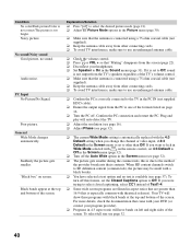
... TV in the PC IN (not supplied HD15 cable). ❑ Ensure the output signal from the PC is connected using a 75-ohm coaxial cable (not supplied). ❑ Keep the antenna cable away from other connecting cords. ❑ To avoid TV interference, make sure to select the desired picture mode (page 21). ❑ Adjust the Picture Mode options in the Sound menu (page 31). If you change the channel or video input, if 4:3 Default in the Screen menu is set 4:3 Default...
... TV in the PC IN (not supplied HD15 cable). ❑ Ensure the output signal from the PC is connected using a 75-ohm coaxial cable (not supplied). ❑ Keep the antenna cable away from other connecting cords. ❑ To avoid TV interference, make sure to select the desired picture mode (page 21). ❑ Adjust the Picture Mode options in the Sound menu (page 31). If you change the channel or video input, if 4:3 Default in the Screen menu is set 4:3 Default...
Operating Instructions
Page 42
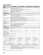
... Connecting cables / Wall-Mount Bracket: SU-WL100 (KDL-26M4000), SU-WL500 (KDL-32M4000, KDL-37M4000, and KDL-40M4000) / 75-ohm coaxial cable / HD15-HD15 cable / Support Belt Kit / TV Stand: RHT-S10 (KDL-40M4000) • Design and specifications are subject to the Table-Top Stand) / Operating Instructions (1) / Quick Setup Guide (1) / Warranty Card (1) / Online Registration Card (U.S.A. Specifications Model System KDL-26M4000 KDL-32M4000 KDL-37M4000 KDL-40M4000 Television system Channel coverage Panel system Speaker output Input/Output jacks Antenna VIDEO IN 1/2 COMPONENT IN 1/2 HDMI...
... Connecting cables / Wall-Mount Bracket: SU-WL100 (KDL-26M4000), SU-WL500 (KDL-32M4000, KDL-37M4000, and KDL-40M4000) / 75-ohm coaxial cable / HD15-HD15 cable / Support Belt Kit / TV Stand: RHT-S10 (KDL-40M4000) • Design and specifications are subject to the Table-Top Stand) / Operating Instructions (1) / Quick Setup Guide (1) / Warranty Card (1) / Online Registration Card (U.S.A. Specifications Model System KDL-26M4000 KDL-32M4000 KDL-37M4000 KDL-40M4000 Television system Channel coverage Panel system Speaker output Input/Output jacks Antenna VIDEO IN 1/2 COMPONENT IN 1/2 HDMI...
Operating Instructions
Page 43
... INPUT button 24, 25 Installing the TV on a wall 8, 9, 10, 11 J JUMP button 24 L Label Channels 33 Label Inputs 37 Language 38 Light Sensor Described 25 M Menu Channel 33 Parental Lock 34 Picture 30 Screen 32 Setup 37 Shortcuts 28 Sound 31 MENU button 22, 25 Movie Rating 36 MUTING button 22 P Parental Lock 28, 34 PC IN 13 PC-PIP 29 Phase 32 Picture 30 PICTURE button 21 Picture Mode 30 POWER button 22, 25 POWER LED 25 Product Support 38 R Rating 34 Remote Control...
... INPUT button 24, 25 Installing the TV on a wall 8, 9, 10, 11 J JUMP button 24 L Label Channels 33 Label Inputs 37 Language 38 Light Sensor Described 25 M Menu Channel 33 Parental Lock 34 Picture 30 Screen 32 Setup 37 Shortcuts 28 Sound 31 MENU button 22, 25 Movie Rating 36 MUTING button 22 P Parental Lock 28, 34 PC IN 13 PC-PIP 29 Phase 32 Picture 30 PICTURE button 21 Picture Mode 30 POWER button 22, 25 POWER LED 25 Product Support 38 R Rating 34 Remote Control...


