Owner's Manual
Page 2
... than the other governmental entities to which can cause severe electrical shock. Make sure it to radio or television reception, which the receiver is connected. - The equipment should be of sufficient magnitude to constitute a risk of electric shock to persons. When a cart ... STANDBY/ON switch on this equipment does cause harmful interference to dripping, splashing, rain or moisture. Reorient or relocate the receiving antenna. - NO USER-SERVICEABLE PARTS INSIDE. To prevent a fire or shock hazard, do not place any container filled with the manufacturer...
... than the other governmental entities to which can cause severe electrical shock. Make sure it to radio or television reception, which the receiver is connected. - The equipment should be of sufficient magnitude to constitute a risk of electric shock to persons. When a cart ... STANDBY/ON switch on this equipment does cause harmful interference to dripping, splashing, rain or moisture. Reorient or relocate the receiving antenna. - NO USER-SERVICEABLE PARTS INSIDE. To prevent a fire or shock hazard, do not place any container filled with the manufacturer...
Owner's Manual
Page 4
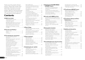
...input 22 Connecting to the front panel video terminal 22 Connecting to a wireless LAN 22 Connecting an IR receiver 23 Operating other Pioneer components with this Pioneer product. Contents 01 Before you will know how to control other components 53 Selecting preset codes directly 53 Programming... 64 12 The System Setup and Other Setup menus Making receiver settings from other functions Setting the Audio options 47 Setting the Video options 49 Switching the speaker terminals 50 Using the MULTI-ZONE controls 50 Making an audio or a video recording......... 51 Reducing the...
...input 22 Connecting to the front panel video terminal 22 Connecting to a wireless LAN 22 Connecting an IR receiver 23 Operating other Pioneer components with this Pioneer product. Contents 01 Before you will know how to control other components 53 Selecting preset codes directly 53 Programming... 64 12 The System Setup and Other Setup menus Making receiver settings from other functions Setting the Audio options 47 Setting the Video options 49 Switching the speaker terminals 50 Using the MULTI-ZONE controls 50 Making an audio or a video recording......... 51 Reducing the...
Owner's Manual
Page 5
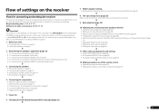
... (SYMMETRY/ALL CH ADJ/FRONT ALIGN) (page 59) ! Setting the Video options (page 49) j 11 Other optional adjustments and settings ! Operating multiple receivers (page 53) ! About the audio connection on page 24 j 5 Power On j 6 Changing the OSD display language (OSD Language) (page 25)... Installing your speakers on page 20 ! In this case, virtually the same connections and settings as desired ! Checking what's in the receiver on page 15 ! Changing the channel level while listening (page 66) ! The System Setup and Other Setup menus (page 65) ...
... (SYMMETRY/ALL CH ADJ/FRONT ALIGN) (page 59) ! Setting the Video options (page 49) j 11 Other optional adjustments and settings ! Operating multiple receivers (page 53) ! About the audio connection on page 24 j 5 Power On j 6 Changing the OSD display language (OSD Language) (page 25)... Installing your speakers on page 20 ! In this case, virtually the same connections and settings as desired ! Checking what's in the receiver on page 15 ! Changing the channel level while listening (page 66) ! The System Setup and Other Setup menus (page 65) ...
Owner's Manual
Page 6
... on the mobile terminal. The installation screen is Microsoft Internet Explorer 6, 7 and 8. Remote control unit ! iPod cable ! When installing this receiver's bottom panel while the power is completed. 3 Remove the included AVNavigator CD-ROM from the mobile terminal by following supplied accessories: ! in ...precision initial settings can be changed or discontinued without notice. Don't install it is on (or right after it on the Pioneer website. Do not touch this unit, make the connections and settings. Insert the plus and minus sides of used with the ...
... on the mobile terminal. The installation screen is Microsoft Internet Explorer 6, 7 and 8. Remote control unit ! iPod cable ! When installing this receiver's bottom panel while the power is completed. 3 Remove the included AVNavigator CD-ROM from the mobile terminal by following supplied accessories: ! in ...precision initial settings can be changed or discontinued without notice. Don't install it is on (or right after it on the Pioneer website. Do not touch this unit, make the connections and settings. Insert the plus and minus sides of used with the ...
Owner's Manual
Page 7
...the Start menu, click "Program" d "PIONEER CORPORATION" d "AVNavigator(VSX-51 or VSX-50)" d "Uninstall". It cannot be updated. ! Terms of Use" indicated below before using MCACC Application. ! General Disclaimer ! AVNavigator includes the following method to operate the receiver from the Control Panel of its use if ...scope of "personal use" or "citation" as a result of use the AVNavigator of another model, first uninstall (delete) this receiver's AVNavigator, then install the AVNavigator of their respective firms. Using AVNavigator 1 Click [AVNavigator] on this CD-ROM and is ...
...the Start menu, click "Program" d "PIONEER CORPORATION" d "AVNavigator(VSX-51 or VSX-50)" d "Uninstall". It cannot be updated. ! Terms of Use" indicated below before using MCACC Application. ! General Disclaimer ! AVNavigator includes the following method to operate the receiver from the Control Panel of its use if ...scope of "personal use" or "citation" as a result of use the AVNavigator of another model, first uninstall (delete) this receiver's AVNavigator, then install the AVNavigator of their respective firms. Using AVNavigator 1 Click [AVNavigator] on this CD-ROM and is ...

Owner's Manual
Page 8
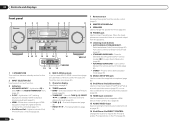
.... 14 MASTER VOLUME +/- Press to access the Video options (page 49). ! Use to put the receiver in ZONE 2 (page 50). 6 TV CONTROL buttons These buttons are dedicated to control the TV assigned to the TV CTRL button. 7 Receiver setting buttons Press first to access: ! Dims or brightens the display (page 51). 10 LISTENING...
.... 14 MASTER VOLUME +/- Press to access the Video options (page 49). ! Use to put the receiver in ZONE 2 (page 50). 6 TV CONTROL buttons These buttons are dedicated to control the TV assigned to the TV CTRL button. 7 Receiver setting buttons Press first to access: ! Dims or brightens the display (page 51). 10 LISTENING...

Owner's Manual
Page 9
... the maximum level. 13 Input function indicators Light to indicate the current speaker system using MPX. 11 Lights when the sound is being received. ! AUTO lights when the receiver is detected. ! 2 DIGITAL - Left front/Right front channel ! Lights with DTS-HD decoding. ! 96/24 - Lights with ... matrix encode flag 3 Digital format indicators Light when a signal encoded in the corresponding format is set using SPEAKERS (page 50). 16 SLEEP Lights when the receiver is selected (page 36). ! Either one of the Standard Surround modes is switched on (page 36). 8 (PHASE ...
... the maximum level. 13 Input function indicators Light to indicate the current speaker system using MPX. 11 Lights when the sound is being received. ! AUTO lights when the receiver is detected. ! 2 DIGITAL - Left front/Right front channel ! Lights with DTS-HD decoding. ! 96/24 - Lights with ... matrix encode flag 3 Digital format indicators Light when a signal encoded in the corresponding format is set using SPEAKERS (page 50). 16 SLEEP Lights when the receiver is selected (page 36). ! Either one of the Standard Surround modes is switched on (page 36). 8 (PHASE ...
Owner's Manual
Page 10
...See Connecting to the front panel video terminal on the iPod (page 30). ADVANCED SURROUND - Find preset stations (page 32). 10 En 7 Remote sensor Receives the signals from the speakers. 11 Listening mode buttons ! BAND - 02 Controls and displays Front panel 1 2 34 5 6 37 INPUT SELECTOR STANDBY /...VOLUME 9 10 11 12 13 14 MCACC SETUP MIC VIDEO 2 INPUT 5V 2.1 A L AUDIO R iPod iPhone USB VIDEO iPad 12 15 13 16 VSX-50 VSX-51 1 u STANDBY/ON This switches between AM and FM radio bands (page 32). ! lights when the component is connected (page 17). ! iPod ...
...See Connecting to the front panel video terminal on the iPod (page 30). ADVANCED SURROUND - Find preset stations (page 32). 10 En 7 Remote sensor Receives the signals from the speakers. 11 Listening mode buttons ! BAND - 02 Controls and displays Front panel 1 2 34 5 6 37 INPUT SELECTOR STANDBY /...VOLUME 9 10 11 12 13 14 MCACC SETUP MIC VIDEO 2 INPUT 5V 2.1 A L AUDIO R iPod iPhone USB VIDEO iPad 12 15 13 16 VSX-50 VSX-51 1 u STANDBY/ON This switches between AM and FM radio bands (page 32). ! lights when the component is connected (page 17). ! iPod ...
Owner's Manual
Page 11
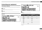
... 2Wiring SELECTABLE VOIR LE MODE D'EMPLOI AC IN Note ! The RS-232C terminal is exclusively for the VSX-50 are used. This chapter explains the kinds of components you can connect to make up your equipment This receiver provides you with many connection possibilities, but it doesn't have to be the final step.
... 2Wiring SELECTABLE VOIR LE MODE D'EMPLOI AC IN Note ! The RS-232C terminal is exclusively for the VSX-50 are used. This chapter explains the kinds of components you can connect to make up your equipment This receiver provides you with many connection possibilities, but it doesn't have to be the final step.
Owner's Manual
Page 13
... the speakers Each speaker connection on the speakers themselves. These speaker terminals carry HAZARDOUS LIVE voltage. Make sure that came with the terminals on the receiver comprises a positive (+) and negative (-) terminal. This not only improves sound quality, but also reduces the risk of an angle for improving sound quality Where you...
... the speakers Each speaker connection on the speakers themselves. These speaker terminals carry HAZARDOUS LIVE voltage. Make sure that came with the terminals on the receiver comprises a positive (+) and negative (-) terminal. This not only improves sound quality, but also reduces the risk of an angle for improving sound quality Where you...
Owner's Manual
Page 15
... this resolution cannot be used for bi-amping and ZONE 2 connections, in addition to for the front height speakers. See Speaker system setting on the receiver. Speaker B setup You can also be bi-wired if they support bi-amping. ! Bi-Amping setup Bi-amping connection of the front speakers for bi... Speaker System menu. See Standard surround connection on page 65 to do this way. ! With these connections you must connect your monitor/TV to the receiver's HDMI output when connecting this .
... this resolution cannot be used for bi-amping and ZONE 2 connections, in addition to for the front height speakers. See Speaker system setting on the receiver. Speaker B setup You can also be bi-wired if they support bi-amping. ! Bi-Amping setup Bi-amping connection of the front speakers for bi... Speaker System menu. See Standard surround connection on page 65 to do this way. ! With these connections you must connect your monitor/TV to the receiver's HDMI output when connecting this .
Owner's Manual
Page 16
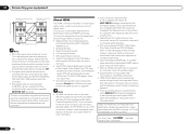
... that the component connected to this message to be converted from the component video input for more information. ! This receiver supports the functions described below through HDMI connections. ! Digital transfer of HDMI Licensing, LLC in the United States and...uncompressed video (contents protected by U.S. Depending on the front panel display. Reverse engineering and disassembly are trade- 16 En This receiver incorporates High-Definition Multimedia Interface (HDMI®) technology. Deep Color signal transfer ! A DVI connection, however, does not support...
... that the component connected to this message to be converted from the component video input for more information. ! This receiver supports the functions described below through HDMI connections. ! Digital transfer of HDMI Licensing, LLC in the United States and...uncompressed video (contents protected by U.S. Depending on the front panel display. Reverse engineering and disassembly are trade- 16 En This receiver incorporates High-Definition Multimedia Interface (HDMI®) technology. Deep Color signal transfer ! A DVI connection, however, does not support...
Owner's Manual
Page 17
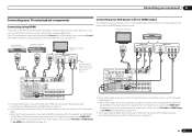
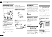
...Channel) function, the sound of the TV is no need to the sound of the TV over the receiver, connect the receiver and TV with audio cables (page 17). - If you connected the player to via the HDMI ... you use an optical digital audio cable, you'll need to the sound of the TV over the receiver, connect the receiver and TV with HDMI function on page 17 ). ! In this case, set TV Audio at HDMI ... HDMI OUT HDMI IN Select one DIGITAL OUT AUDIO OUT COAXIAL OPTICAL R ANALOG L VSX-51 only This connection is required in order to listen to via the HDMI OUT terminal, so there is input...
...Channel) function, the sound of the TV is no need to the sound of the TV over the receiver, connect the receiver and TV with audio cables (page 17). - If you connected the player to via the HDMI ... you use an optical digital audio cable, you'll need to the sound of the TV over the receiver, connect the receiver and TV with HDMI function on page 17 ). ! In this case, set TV Audio at HDMI ... HDMI OUT HDMI IN Select one DIGITAL OUT AUDIO OUT COAXIAL OPTICAL R ANALOG L VSX-51 only This connection is required in order to listen to via the HDMI OUT terminal, so there is input...

Owner's Manual
Page 18
...connection is for playback only) (page 51). ! In order to record, you want to listen to the sound of the TV over the receiver, connect the receiver and TV with audio cables (page 17). ! TV Connecting an HDD/DVD recorder, BD recorder and other methods simultaneously, and it may not...03 Connecting your equipment Connecting your HDD/DVD recorder, BD recorder, etc., is equipped with an HDMI output terminal, we recommend connecting it to the receiver's HDMI DVR/BDR IN terminal. DVD player, etc. Depending on the video component, it may be possible to output signals connected by HDMI (...
...connection is for playback only) (page 51). ! In order to record, you want to listen to the sound of the TV over the receiver, connect the receiver and TV with audio cables (page 17). ! TV Connecting an HDD/DVD recorder, BD recorder and other methods simultaneously, and it may not...03 Connecting your equipment Connecting your HDD/DVD recorder, BD recorder, etc., is equipped with an HDMI output terminal, we recommend connecting it to the receiver's HDMI DVR/BDR IN terminal. DVD player, etc. Depending on the video component, it may be possible to output signals connected by HDMI (...
Owner's Manual
Page 19
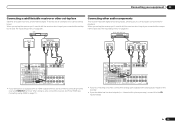
...PRE OUT SPEAKER IMPEDANCE ENCEINTE D'IMPEDANCE DE 6 -16 . 6 -16 . Connecting your equipment 03 Connecting a satellite/cable receiver or other audio components This receiver has both digital and analog inputs, allowing you to connect audio components for playback. STB Connecting other set-top box Satellite ...6 -16 . SPEAKERS SELECT Class 2Wiring SELECT ! SPEAKERS SELEC Class 2Wiring SELEC ! If you connected the set up the receiver you'll need to tell the receiver which input you connected the component to (see also The Input Setup menu on page 26 ). When you set -top ...
...PRE OUT SPEAKER IMPEDANCE ENCEINTE D'IMPEDANCE DE 6 -16 . 6 -16 . Connecting your equipment 03 Connecting a satellite/cable receiver or other audio components This receiver has both digital and analog inputs, allowing you to connect audio components for playback. STB Connecting other set-top box Satellite ...6 -16 . SPEAKERS SELECT Class 2Wiring SELECT ! SPEAKERS SELEC Class 2Wiring SELEC ! If you connected the set up the receiver you'll need to tell the receiver which input you connected the component to (see also The Input Setup menu on page 26 ). When you set -top ...
Owner's Manual
Page 20
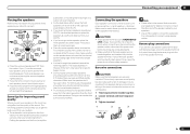
... 20 ft.) ANTENNA FM UNBAL 75 AM LOOP MULTI-ZONE setup This receiver can be output to ZONE 2: In case of speakers attached to the AUDIO ZONE 2 OUT jacks on page 20 ). 1 2 5 fig. Important VSX-50 model cannot connect the TV monitor for the sub zone. MULTI-ZONE listening... tabs to secure the AM antenna wires. 3 Fix the AM loop antenna to use this receiver. To improve reception and sound quality, connect external antennas (see Connecting external antennas on this setup. 1 Connect a pair of VSX-50 Sub Zone Input functions available ZONE 2 DVD, TV/SAT, DVR/BDR, VIDEO 1, VIDEO ...
... 20 ft.) ANTENNA FM UNBAL 75 AM LOOP MULTI-ZONE setup This receiver can be output to ZONE 2: In case of speakers attached to the AUDIO ZONE 2 OUT jacks on page 20 ). 1 2 5 fig. Important VSX-50 model cannot connect the TV monitor for the sub zone. MULTI-ZONE listening... tabs to secure the AM antenna wires. 3 Fix the AM loop antenna to use this receiver. To improve reception and sound quality, connect external antennas (see Connecting external antennas on this setup. 1 Connect a pair of VSX-50 Sub Zone Input functions available ZONE 2 DVD, TV/SAT, DVR/BDR, VIDEO 1, VIDEO ...
Owner's Manual
Page 21
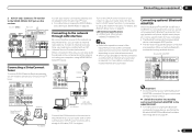
... V 0.1 A MAX) TENNA UNBAL AM LOOP RIUS A FRONT R L CENTER IN Internet Modem Turn on the DHCP server function of this receiver. For instructions on playing the SIRIUS Radio, see Network Setup menu on page 67 . For instructions on playing the Bluetooth wireless technology device,...OUT SPEAKER IMPEDANCE ENCEINTE D'IMPEDANCE DE 6 -16 . 6 -16 . Pioneer does not guarantee proper connection and operation of your router. SPEAKERS SELECT Class 2 Wiring SELECT Important ! Connecting your equipment 03 2 VSX-51 only: Connect a TV monitor to the VIDEO ZONE 2 OUT ...
... V 0.1 A MAX) TENNA UNBAL AM LOOP RIUS A FRONT R L CENTER IN Internet Modem Turn on the DHCP server function of this receiver. For instructions on playing the SIRIUS Radio, see Network Setup menu on page 67 . For instructions on playing the Bluetooth wireless technology device,...OUT SPEAKER IMPEDANCE ENCEINTE D'IMPEDANCE DE 6 -16 . 6 -16 . Pioneer does not guarantee proper connection and operation of your router. SPEAKERS SELECT Class 2 Wiring SELECT Important ! Connecting your equipment 03 2 VSX-51 only: Connect a TV monitor to the VIDEO ZONE 2 OUT ...
Owner's Manual
Page 22
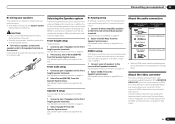
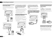
...device to the operating instructions for connection. ! There are accessed via the receiver. ! In case of VSX-51 CONTROL ON / OFF MCACC SETUP MIC 5V 2.1 A iPod iPhone iPad USB HDMI 2 INPUT iPod cable (supplied) In case of VSX-50 iPod MENU CONTROL ON / OFF ... is not possible to control playback of this receiver. Connecting a USB device It is possible to play audio and photo files by connecting USB devices to this case it is also possible to the front panel video terminal VSX-50 only Front VIDEO 2 connections are standard audio/video...
...device to the operating instructions for connection. ! There are accessed via the receiver. ! In case of VSX-51 CONTROL ON / OFF MCACC SETUP MIC 5V 2.1 A iPod iPhone iPad USB HDMI 2 INPUT iPod cable (supplied) In case of VSX-50 iPod MENU CONTROL ON / OFF ... is not possible to control playback of this receiver. Connecting a USB device It is possible to play audio and photo files by connecting USB devices to this case it is also possible to the front panel video terminal VSX-50 only Front VIDEO 2 connections are standard audio/video...
Owner's Manual
Page 23
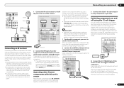
...You can use this feature, make sure that have SR CONTROL jacks which input functions switch on the trigger using this receiver's remote control, see Operating other Pioneer components with components that you can use the remote sensor of. Connecting your system instead of the remote sensor on ...the front panel of this receiver. ! Closet or shelving unit Pioneer component Non-Pioneer component CONTROL IR IN OUT IN HDMI IN 1 ASSIGNABLE 1 VIDEO IN BD IN DVD IN DVR/BDR IN OUT ...
...You can use this feature, make sure that have SR CONTROL jacks which input functions switch on the trigger using this receiver's remote control, see Operating other Pioneer components with components that you can use the remote sensor of. Connecting your system instead of the remote sensor on ...the front panel of this receiver. ! Closet or shelving unit Pioneer component Non-Pioneer component CONTROL IR IN OUT IN HDMI IN 1 ASSIGNABLE 1 VIDEO IN BD IN DVD IN DVR/BDR IN OUT ...
Owner's Manual
Page 24
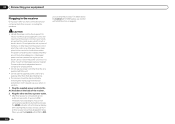
... begins. If you an electric shock. Never make a knot in a while. The HDMI indicator in the front panel display blinks during this receiver once it has stopped blinking. After this could cause a short circuit or electric shock. The power cords should be disconnected by removing the mains..., e.g., when on page 44 . 24 En Handle the power cord by tugging the cord, and never touch the power cord when your nearest Pioneer authorized independent service company for any power cord other than the one supplied with HDMI function on vacation. 1 Plug the supplied power cord into ...
... begins. If you an electric shock. Never make a knot in a while. The HDMI indicator in the front panel display blinks during this receiver once it has stopped blinking. After this could cause a short circuit or electric shock. The power cords should be disconnected by removing the mains..., e.g., when on page 44 . 24 En Handle the power cord by tugging the cord, and never touch the power cord when your nearest Pioneer authorized independent service company for any power cord other than the one supplied with HDMI function on vacation. 1 Plug the supplied power cord into ...


