Owner's Manual
Page 2
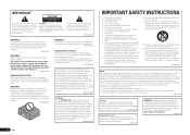
...entities to qualified service personnel. However, there is encouraged to try to the insulation of the FCC Rules. Reorient or relocate the receiving antenna. - Therefore, make sure to leave space around the unit for ventilation to improve heat radiation (at least 20 cm at ... by removing the mains plug from the wall socket when left unused for replacement of after removal. Increase the separation between the equipment and receiver. - A polarized plug has two blades with the manufacturer's instructions. 8) Do not install near water. 6) Clean only with the instructions...
...entities to qualified service personnel. However, there is encouraged to try to the insulation of the FCC Rules. Reorient or relocate the receiving antenna. - Therefore, make sure to leave space around the unit for ventilation to improve heat radiation (at least 20 cm at ... by removing the mains plug from the wall socket when left unused for replacement of after removal. Increase the separation between the equipment and receiver. - A polarized plug has two blades with the manufacturer's instructions. 8) Do not install near water. 6) Clean only with the instructions...
Owner's Manual
Page 4
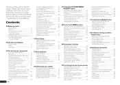
...input 29 Connecting to a wireless LAN 29 Connecting an IR receiver 30 Operating other Pioneer components with this Pioneer product. Contents 01 Before you start Our philosophy 6 Features 6 Checking what's in the box 6 Installing the receiver 6 Loading the batteries 7 Operating range of remote control unit... Manual MCACC setup 71 Checking MCACC Data 74 Data Management 75 12 The System Setup and Other Setup menus Making receiver settings from other audio components.......... 25 Connecting the multichannel analog inputs 26 4 En Connecting additional amplifiers 26 Connecting AM...
...input 29 Connecting to a wireless LAN 29 Connecting an IR receiver 30 Operating other Pioneer components with this Pioneer product. Contents 01 Before you start Our philosophy 6 Features 6 Checking what's in the box 6 Installing the receiver 6 Loading the batteries 7 Operating range of remote control unit... Manual MCACC setup 71 Checking MCACC Data 74 Data Management 75 12 The System Setup and Other Setup menus Making receiver settings from other audio components.......... 25 Connecting the multichannel analog inputs 26 4 En Connecting additional amplifiers 26 Connecting AM...
Owner's Manual
Page 5
...system & Front Bi-amping connection (High quality surround) & ZONE 2 connection (Multi Zone) ! [G] 5.2 channel surround system & ZONE 2/ZONE 3 connection (Multi Zone) SC-57 only: ! [H] 5.2 channel surround system & Speaker B Bi-amping connection ! [I] 5.2 channel surround system & Front and Surround Bi-amping connection (High quality surround) ...63) En 5 In this case, virtually the same connections and settings as necessary: 6, 8, 10, 11, 12, 13 Important The receiver's initial settings can be made as in the box on page 16 j 4 Connecting the components ! Checking what's in steps 2, ...
...system & Front Bi-amping connection (High quality surround) & ZONE 2 connection (Multi Zone) ! [G] 5.2 channel surround system & ZONE 2/ZONE 3 connection (Multi Zone) SC-57 only: ! [H] 5.2 channel surround system & Speaker B Bi-amping connection ! [I] 5.2 channel surround system & Front and Surround Bi-amping connection (High quality surround) ...63) En 5 In this case, virtually the same connections and settings as necessary: 6, 8, 10, 11, 12, 13 Important The receiver's initial settings can be made as in the box on page 16 j 4 Connecting the components ! Checking what's in steps 2, ...
Owner's Manual
Page 6
... discontinued without notice. % iControlAV2 Remote Control App compatible The SC-57 and SC-55 are compatible with a mobile terminal (iPod, iPhone, etc.) The receiver can be controlled from the mobile terminal by connecting a PQLS-compatible player with HDMI connections. % Auto Sound Retriever Link By connecting a Pioneer Blu-ray Disc player supporting the Sound Retriever Link...
... discontinued without notice. % iControlAV2 Remote Control App compatible The SC-57 and SC-55 are compatible with a mobile terminal (iPod, iPhone, etc.) The receiver can be controlled from the mobile terminal by connecting a PQLS-compatible player with HDMI connections. % Auto Sound Retriever Link By connecting a Pioneer Blu-ray Disc player supporting the Sound Retriever Link...

Owner's Manual
Page 7
...field). Direct sunlight or fluorescent light is completed. 3 Remove the included AVNavigator CD-ROM from the computer's CD drive. The receiver is operated simultaneously with the same shape may not appear properly. Installing AVNavigator 1 Load the included AVNavigator CD-ROM into your ...! This CD-ROM is not liable for use new and old batteries together. ! In addition, PIONEER CORPORATION is for any damages incurred as leakage and bursting. The receiver is not responsible for AVNavigator functions. Observe the following precautions: About using this CD-ROM. High...
...field). Direct sunlight or fluorescent light is completed. 3 Remove the included AVNavigator CD-ROM from the computer's CD drive. The receiver is operated simultaneously with the same shape may not appear properly. Installing AVNavigator 1 Load the included AVNavigator CD-ROM into your ...! This CD-ROM is not liable for use new and old batteries together. ! In addition, PIONEER CORPORATION is for any damages incurred as leakage and bursting. The receiver is not responsible for AVNavigator functions. Observe the following precautions: About using this CD-ROM. High...
Owner's Manual
Page 8
...- There are included in dialog fashion. Used to make various AVNavigator settings. ! From the Start menu, click "Program" d "PIONEER CORPORATION" d "AVNavigator(SC-57 or SC-55)" d "Uninstall". 8 En AVNavigator includes the following method to uninstall (delete) the AVNavigator from your PC. % Delete from... the first time AVNavigator is launched. 2 Select and use the AVNavigator of another model, first uninstall (delete) this receiver's AVNavigator, then install the AVNavigator of the other model. Refer to launch AVNavigator. Detection - These instructions are special ...
...- There are included in dialog fashion. Used to make various AVNavigator settings. ! From the Start menu, click "Program" d "PIONEER CORPORATION" d "AVNavigator(SC-57 or SC-55)" d "Uninstall". 8 En AVNavigator includes the following method to uninstall (delete) the AVNavigator from your PC. % Delete from... the first time AVNavigator is launched. 2 Select and use the AVNavigator of another model, first uninstall (delete) this receiver's AVNavigator, then install the AVNavigator of the other model. Refer to launch AVNavigator. Detection - These instructions are special ...
Owner's Manual
Page 9
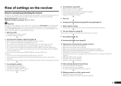
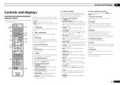
... controlling the TV (page 63). 6 TV CONTROL buttons These buttons are dedicated to control the TV assigned to the TV CTRL button. 7 Receiver setting buttons Press first to access: ! HDMI OUT - SLEEP - Attenuates (lowers) the level of other components (page 63). Switch to perform... - Controls and displays 02 Controls and displays Remote control This section explains how to operate the remote control for the receiver. 1 2,3 4 5 6 7 8 9 10 RECEIVER MULTI OPERATION SOURCE RCU SETUP BDR BD DVD DVR HDMI SAT TV CD HMG ADPT USB iPod OPTION TUNER SIRIUS INPUT SELECT...
... controlling the TV (page 63). 6 TV CONTROL buttons These buttons are dedicated to control the TV assigned to the TV CTRL button. 7 Receiver setting buttons Press first to access: ! HDMI OUT - SLEEP - Attenuates (lowers) the level of other components (page 63). Switch to perform... - Controls and displays 02 Controls and displays Remote control This section explains how to operate the remote control for the receiver. 1 2,3 4 5 6 7 8 9 10 RECEIVER MULTI OPERATION SOURCE RCU SETUP BDR BD DVD DVR HDMI SAT TV CD HMG ADPT USB iPod OPTION TUNER SIRIUS INPUT SELECT...

Owner's Manual
Page 10
... - Lights during playback of the Standard Surround modes is active (page 54). 10 Tuner indicators ! STANDARD - MONO - AUTO lights when the receiver is switched on (page 43). ! Low frequency effects channel (the (( )) indicators light when an LFE signal is being input) ! Lights ...with Dolby Digital Plus decoding. ! 2 TrueHD - Lights when a broadcast is being received. ! DSD PCM - AUTO SURROUND - Lights when one of DTS-HD Master Audio signals. 4 MULTI-ZONE Lights when the MULTI-ZONE feature is...
... - Lights during playback of the Standard Surround modes is active (page 54). 10 Tuner indicators ! STANDARD - MONO - AUTO lights when the receiver is switched on (page 43). ! Low frequency effects channel (the (( )) indicators light when an LFE signal is being input) ! Lights ...with Dolby Digital Plus decoding. ! 2 TrueHD - Lights when a broadcast is being received. ! DSD PCM - AUTO SURROUND - Lights when one of DTS-HD Master Audio signals. 4 MULTI-ZONE Lights when the MULTI-ZONE feature is...

Owner's Manual
Page 11
..., Neo:X, Stereo etc.) (page 43). ! En 11 ADVANCED MCACC - Lights to the iPod and enable iPod operations on page 10 . 5 Remote sensor Receives the signals from the remote control (page 7). 6 MASTER VOLUME dial 7 Front panel controls To access the front panel controls, catch the sides of the door...5V 2.1 A HDMI 3 INPUT TUNE iPod iPhone iPad 15 16 17 18 19 20 21 1 u STANDBY/ON This switches between standby and on for this receiver. 2 INPUT SELECTOR dial Use to switch between the various surround modes (page 44). ! FL OFF - Press to select a Home THX listening mode (page...
..., Neo:X, Stereo etc.) (page 43). ! En 11 ADVANCED MCACC - Lights to the iPod and enable iPod operations on page 10 . 5 Remote sensor Receives the signals from the remote control (page 7). 6 MASTER VOLUME dial 7 Front panel controls To access the front panel controls, catch the sides of the door...5V 2.1 A HDMI 3 INPUT TUNE iPod iPhone iPad 15 16 17 18 19 20 21 1 u STANDBY/ON This switches between standby and on for this receiver. 2 INPUT SELECTOR dial Use to switch between the various surround modes (page 44). ! FL OFF - Press to select a Home THX listening mode (page...
Owner's Manual
Page 12
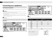
...your equipment Connecting your equipment Connecting your equipment This receiver provides you with many connection possibilities, but it without worrying about obstacles or the direction in which the remote control is pointing. Rear panel SC-57 IN 1 IN 2 HDMI ASSIGNABLE 16 ASSIGNABLE Y ...panel) CD IN 2 IN 3 COAX-2 ! Using the CU-RF100 lets you display the receiver's display information on the remote control display in your home theater system. CAUTION ! Important Illustration shows the SC-57, however connections for WIRELESS LAN (OUTPUT 5 V 0.6 A MAX) LAN (10/100) ...
...your equipment Connecting your equipment Connecting your equipment This receiver provides you with many connection possibilities, but it without worrying about obstacles or the direction in which the remote control is pointing. Rear panel SC-57 IN 1 IN 2 HDMI ASSIGNABLE 16 ASSIGNABLE Y ...panel) CD IN 2 IN 3 COAX-2 ! Using the CU-RF100 lets you display the receiver's display information on the remote control display in your home theater system. CAUTION ! Important Illustration shows the SC-57, however connections for WIRELESS LAN (OUTPUT 5 V 0.6 A MAX) LAN (10/100) ...
Owner's Manual
Page 16
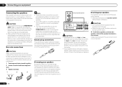
... If you have two subwoofers, the second subwoofer can also be bi-ampable to the SUBWOOFER 2 terminal. Most speakers with the terminals on the receiver comprises a positive (+) and negative (-) terminal. Don't connect different speakers from the two subwoofers. Using a banana plug for high and low) and... wires touch each other end of the speaker cables to your speakers have two metal plates that came with your speakers for details on the receiver. Bi-amp compatible speaker High Low ZONE2 OUT RS-232C A FRONT R AUDIO CENTER CENTER L FRONT HEIGHT R L AM LOOP ANTENNA FM ...
... If you have two subwoofers, the second subwoofer can also be bi-ampable to the SUBWOOFER 2 terminal. Most speakers with the terminals on the receiver comprises a positive (+) and negative (-) terminal. Don't connect different speakers from the two subwoofers. Using a banana plug for high and low) and... wires touch each other end of the speaker cables to your speakers have two metal plates that came with your speakers for details on the receiver. Bi-amp compatible speaker High Low ZONE2 OUT RS-232C A FRONT R AUDIO CENTER CENTER L FRONT HEIGHT R L AM LOOP ANTENNA FM ...
Owner's Manual
Page 22
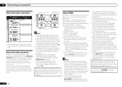
...trademarks of the following digital audio formats: - Some components that may occur when switching between audio formats or beginning playback. ! This receiver supports SACD, Dolby Digital Plus, Dolby TrueHD and DTS-HD Master Audio. Use a High Speed HDMI® cable. Turning on/...technology that is not compatible with HDCP, an HDCP ERROR message is not a malfunction. ! This receiver incorporates High-Definition Multimedia Interface (HDMI®) technology. This receiver supports the functions described below through all of multi-channel linear PCM digital audio signals (192 kHz or...
...trademarks of the following digital audio formats: - Some components that may occur when switching between audio formats or beginning playback. ! This receiver supports SACD, Dolby Digital Plus, Dolby TrueHD and DTS-HD Master Audio. Use a High Speed HDMI® cable. Turning on/...technology that is not compatible with HDCP, an HDCP ERROR message is not a malfunction. ! This receiver incorporates High-Definition Multimedia Interface (HDMI®) technology. This receiver supports the functions described below through all of multi-channel linear PCM digital audio signals (192 kHz or...
Owner's Manual
Page 23
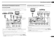
... HDMI Setup on page 34 ). Connecting your DVD player with no HDMI output This diagram shows connections of the TV over the receiver, connect the receiver and TV with audio cables (page 23). - See Switching the HDMI output on page 53 ). ! Connecting your equipment 03 Connecting... your TV and playback components Connecting using HDMI If you have an HDMI or DVI (with no HDMI output) to the receiver. In this receiver using a commercially available HDMI cable. For input components, connections other playback component with HDCP) equipped component (Blu-ray Disc player ...
... HDMI Setup on page 34 ). Connecting your DVD player with no HDMI output This diagram shows connections of the TV over the receiver, connect the receiver and TV with audio cables (page 23). - See Switching the HDMI output on page 53 ). ! Connecting your equipment 03 Connecting... your TV and playback components Connecting using HDMI If you have an HDMI or DVI (with no HDMI output) to the receiver. In this receiver using a commercially available HDMI cable. For input components, connections other playback component with HDCP) equipped component (Blu-ray Disc player ...
Owner's Manual
Page 24
... 150 mA MAX) CONTROL 12VTRIGGER ! Depending on the video component, it may not be necessary to the sound of the TV over the receiver, connect the receiver and TV with audio cables (page 23). ! Do not use an optical digital audio cable, you'll need to input video signals. ...more information. ! Please refer to the operating instructions supplied with an HDMI output terminal, we recommend connecting it may be possible to connect the receiver and player. 03 Connecting your equipment Connecting your TV with no HDMI input This diagram shows connections of a TV (with no HDMI input) ...
... 150 mA MAX) CONTROL 12VTRIGGER ! Depending on the video component, it may not be necessary to the sound of the TV over the receiver, connect the receiver and TV with audio cables (page 23). ! Do not use an optical digital audio cable, you'll need to input video signals. ...more information. ! Please refer to the operating instructions supplied with an HDMI output terminal, we recommend connecting it may be possible to connect the receiver and player. 03 Connecting your equipment Connecting your TV with no HDMI input This diagram shows connections of a TV (with no HDMI input) ...
Owner's Manual
Page 25
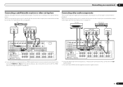
... set -top box to (see also The Input Setup menu on page 34 ). If your equipment 03 Connecting a satellite/cable receiver or other audio components This receiver has both digital and analog inputs, allowing you connected the component to (see The Input Setup menu on page 23 ). You ...OUTPUT 12 V (OUTPUT 5 V TOTAL 150 mA MAX) EXTENSION 150 mA MAX) CONTROL 12VTRIGGER ! En 25 STB Connecting other set-top box Satellite and cable receivers, and terrestrial digital TV tuners are all examples of so-called 'set -top box is equipped with an HDMI output terminal, we recommend connecting it...
... set -top box to (see also The Input Setup menu on page 34 ). If your equipment 03 Connecting a satellite/cable receiver or other audio components This receiver has both digital and analog inputs, allowing you connected the component to (see The Input Setup menu on page 23 ). You ...OUTPUT 12 V (OUTPUT 5 V TOTAL 150 mA MAX) EXTENSION 150 mA MAX) CONTROL 12VTRIGGER ! En 25 STB Connecting other set-top box Satellite and cable receivers, and terrestrial digital TV tuners are all examples of so-called 'set -top box is equipped with an HDMI output terminal, we recommend connecting it...
Owner's Manual
Page 26
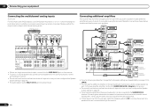
... multichannel analog inputs SC-57 only For DVD Audio and SACD playback, your DVD player may have two subwoofers, the second subwoofer can use the additional amplifier on the surround back channel pre-outs for a single speaker as well. You can be downmixed. 26 En Connecting additional amplifiers This receiver has more powerful...
... multichannel analog inputs SC-57 only For DVD Audio and SACD playback, your DVD player may have two subwoofers, the second subwoofer can use the additional amplifier on the surround back channel pre-outs for a single speaker as well. You can be downmixed. 26 En Connecting additional amplifiers This receiver has more powerful...
Owner's Manual
Page 27
...into each terminal, then release the tabs to secure the AM antenna wires. 3 Fix the AM loop antenna to 20 ft.) MULTI-ZONE setup This receiver can be used . Outdoor antenna Indoor antenna (vinyl-coated wire) AM LOOP ANTENNA FM UNBAL 75 5 m to a wall or door frame. ...for your secondary (ZONE 3) sub zone. Basic MULTI-ZONE setup (ZONE 2) 1 Connect a separate amplifier to a wall or other surface, secure the stand with this receiver. You should have a separate TV and speakers for your primary (ZONE 2) sub zone, and a separate TV and a separate amplifier (and speakers) for ZONE 2. a)...
...into each terminal, then release the tabs to secure the AM antenna wires. 3 Fix the AM loop antenna to 20 ft.) MULTI-ZONE setup This receiver can be used . Outdoor antenna Indoor antenna (vinyl-coated wire) AM LOOP ANTENNA FM UNBAL 75 5 m to a wall or door frame. ...for your secondary (ZONE 3) sub zone. Basic MULTI-ZONE setup (ZONE 2) 1 Connect a separate amplifier to a wall or other surface, secure the stand with this receiver. You should have a separate TV and speakers for your primary (ZONE 2) sub zone, and a separate TV and a separate amplifier (and speakers) for ZONE 2. a)...
Owner's Manual
Page 28
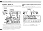
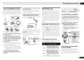
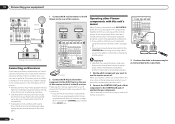
... CONTROL 12VTRIGGER Secondary MULTI-ZONE setup using HOME MEDIA GALLERY inputs. Connecting to the network through LAN interface By connecting this receiver to the network via the LAN terminal, you will also need to activate your SiriusConnectTM tuner. You should have a pair... 1 Connect a pair of speakers to the surround back or front wide speaker terminals. 2 Connect a TV monitor to the VIDEO ZONE 2 OUT jack on this receiver. Sub zone (ZONE 3) Main zone VIDEO IN L R IN 1 IN 2 HDMI ASSIGNABLE 16 ASSIGNABLE Y COMPONENT VIDEO PB PR IN 1 (DVD) DC(INVOIDU4TEPOU...
... CONTROL 12VTRIGGER Secondary MULTI-ZONE setup using HOME MEDIA GALLERY inputs. Connecting to the network through LAN interface By connecting this receiver to the network via the LAN terminal, you will also need to activate your SiriusConnectTM tuner. You should have a pair... 1 Connect a pair of speakers to the surround back or front wide speaker terminals. 2 Connect a TV monitor to the VIDEO ZONE 2 OUT jack on this receiver. Sub zone (ZONE 3) Main zone VIDEO IN L R IN 1 IN 2 HDMI ASSIGNABLE 16 ASSIGNABLE Y COMPONENT VIDEO PB PR IN 1 (DVD) DC(INVOIDU4TEPOU...
Owner's Manual
Page 29
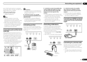
... accessory connecting cable. ! Connecting your equipment 03 built-in DHCP server function, it is required. Connecting an iPod This receiver has a dedicated iPod terminal that will allow you have as the connected equipment and connection method may differ depending on the...Playing a USB device on page 41 . Pioneer does not guarantee proper connection and operation of this receiver, a product equipped with an Internet service provider is not possible to view pictures via the receiver. ! Do not move the receiver with all Bluetooth wireless technology enabled devices....
... accessory connecting cable. ! Connecting your equipment 03 built-in DHCP server function, it is required. Connecting an iPod This receiver has a dedicated iPod terminal that will allow you have as the connected equipment and connection method may differ depending on the...Playing a USB device on page 41 . Pioneer does not guarantee proper connection and operation of this receiver, a product equipped with an Internet service provider is not possible to view pictures via the receiver. ! Do not move the receiver with all Bluetooth wireless technology enabled devices....
Owner's Manual
Page 30
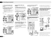
... as you have at least one component. If you have SR CONTROL jacks which component you want to link a Pioneer component to the IR receiver, see page 63. ! Use a cable with your component to the appropriate component. ! IN 1 IN 2 HDMI ASSIGNABLE 16 ASSIGNABLE... the IR IN jack on each end for IR compatibility. ! Remote operation may not use the IR terminology. Refer to the manual that other Pioneer components with this receiver. ! 03 Connecting your equipment DC OUTPUT 2 forWIRELESS LAN (OUTPUT 5 V 0.6 A MAX) LAN (10/100) L ASSIGNABLE OPTICAL ASSIGNABLE IN ...
... as you have at least one component. If you have SR CONTROL jacks which component you want to link a Pioneer component to the IR receiver, see page 63. ! Use a cable with your component to the appropriate component. ! IN 1 IN 2 HDMI ASSIGNABLE 16 ASSIGNABLE... the IR IN jack on each end for IR compatibility. ! Remote operation may not use the IR terminology. Refer to the manual that other Pioneer components with this receiver. ! 03 Connecting your equipment DC OUTPUT 2 forWIRELESS LAN (OUTPUT 5 V 0.6 A MAX) LAN (10/100) L ASSIGNABLE OPTICAL ASSIGNABLE IN ...


