
Owner's Manual
Page 1
Operating Instructions audio/video multi-channel receiver 37 SC35 SC-
Operating Instructions audio/video multi-channel receiver 37 SC35 SC-
Owner's Manual
Page 3
...D3-4-2-2-2a*_A1_En Product Name: AUDIO/VIDEO MULTI-CHANNEL RECEIVER Model Number: SC-37 / SC-35 Responsible Party Name: PIONEER ELECTRONICS (USA) INC. SERVICE SUPPORT DIVISION Address: 1925 E. Increase the separation between the equipment and receiver. - D8-10-1-2_A1_En Information to User Alterations or ...against harmful interference in accordance with items (such as radios and televisions, use , the plug must accept any interference received, including interference that to use shielded cables and connectors for example, when on a circuit different from that may not ...
...D3-4-2-2-2a*_A1_En Product Name: AUDIO/VIDEO MULTI-CHANNEL RECEIVER Model Number: SC-37 / SC-35 Responsible Party Name: PIONEER ELECTRONICS (USA) INC. SERVICE SUPPORT DIVISION Address: 1925 E. Increase the separation between the equipment and receiver. - D8-10-1-2_A1_En Information to User Alterations or ...against harmful interference in accordance with items (such as radios and televisions, use , the plug must accept any interference received, including interference that to use shielded cables and connectors for example, when on a circuit different from that may not ...
Owner's Manual
Page 5
...of remote control unit 11 Flow for operating the receiver with RF two-way communications (SC-37 only 11 02 Controls and displays Remote control (In case of SC-37 12 Remote control display 13 RF adapter 14 Remote control (In case of SC-35 15 Display 16 Front panel 18 03 ...8482; tuner 39 Connecting an iPod 40 Connecting a USB device 40 Connecting a USB device for Advanced MCACC output 40 Connecting an IR receiver 41 Operating other Pioneer components with this unit's sensor 41 Switching components on a USB memory device 50 About playable file formats 51 Listening to the radio ...
...of remote control unit 11 Flow for operating the receiver with RF two-way communications (SC-37 only 11 02 Controls and displays Remote control (In case of SC-37 12 Remote control display 13 RF adapter 14 Remote control (In case of SC-35 15 Display 16 Front panel 18 03 ...8482; tuner 39 Connecting an iPod 40 Connecting a USB device 40 Connecting a USB device for Advanced MCACC output 40 Connecting an IR receiver 41 Operating other Pioneer components with this unit's sensor 41 Switching components on a USB memory device 50 About playable file formats 51 Listening to the radio ...
Owner's Manual
Page 6
...using Phase Control and Full Band Phase Control (SC-37 only 63 07 Playback with HOME MEDIA GALLERY inputs (SC-37 only) Enjoying the Home Media Gallery 64 Features of Home Media Gallery 64 Introduction 64 Authorizing this receiver 64 Playback with Home Media Gallery 65 Playing ...system settings 81 Resetting the system 82 Default system settings 82 10 Controlling the rest of your system (In case of SC-37) About the Remote Setup menu 83 Operating multiple receivers 84 Setting the remote to control other components . . . . 84 Selecting preset codes directly 84 Programming signals from...
...using Phase Control and Full Band Phase Control (SC-37 only 63 07 Playback with HOME MEDIA GALLERY inputs (SC-37 only) Enjoying the Home Media Gallery 64 Features of Home Media Gallery 64 Introduction 64 Authorizing this receiver 64 Playback with Home Media Gallery 65 Playing ...system settings 81 Resetting the system 82 Default system settings 82 10 Controlling the rest of your system (In case of SC-37) About the Remote Setup menu 83 Operating multiple receivers 84 Setting the remote to control other components . . . . 84 Selecting preset codes directly 84 Programming signals from...
Owner's Manual
Page 7
... 119 Volume Setup 119 Remote Control Mode Setup 119 Flicker Reduction Setup 120 RF Remote Setup (SC-37 only 120 EXTENSION Setup (SC-35 only 120 Multi Channel Input Setup 120 11 The Advanced MCACC menu Making receiver settings from the Advanced MCACC menu 104 Automatic MCACC (Expert 104 Manual MCACC setup 106 Fine...
... 119 Volume Setup 119 Remote Control Mode Setup 119 Flicker Reduction Setup 120 RF Remote Setup (SC-37 only 120 EXTENSION Setup (SC-35 only 120 Multi Channel Input Setup 120 11 The Advanced MCACC menu Making receiver settings from the Advanced MCACC menu 104 Automatic MCACC (Expert 104 Manual MCACC setup 106 Fine...
Owner's Manual
Page 8
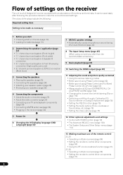
... the Video options (page 78) 12 Other optional adjustments and settings • Control with an abundance of the remote control SC-37: • Operating multiple receivers (page 84) • Setting the remote to control other components (page 84) • Using the RF communications function (page 91...Band Phase Control (SC-37 only) (page 63) • Measuring the all EQ type (SYMMETRY/ALL CH ADJ/FRONT ALIGN) (page 104) • Changing the channel level while listening (Tip on page 116) • Switching on the receiver The unit is a full-fledged AV receiver equipped with HDMI ...
... the Video options (page 78) 12 Other optional adjustments and settings • Control with an abundance of the remote control SC-37: • Operating multiple receivers (page 84) • Setting the remote to control other components (page 84) • Using the RF communications function (page 91...Band Phase Control (SC-37 only) (page 63) • Measuring the all EQ type (SYMMETRY/ALL CH ADJ/FRONT ALIGN) (page 104) • Changing the channel level while listening (Tip on page 116) • Switching on the receiver The unit is a full-fledged AV receiver equipped with HDMI ...
Owner's Manual
Page 9
...PQLS1 Jitterless high quality playback is possible by connecting a PQLS-compatible player with the SC-35. 9 En SC-37: PQLS Bit-stream/PQLS Multi Surround/PQLS 2ch Audio. We do this receiver to the network via LAN is possible from an iPhone or iPod touch by ...the sound field's sense of threedimensionality and air, producing presence and expansion. • Internet Radio By connecting this by downloading a Pioneer original application (iControlAV) from a computer connected on the same LAN as shown below. This new generation reference amplifier offers outstanding performance...
...PQLS1 Jitterless high quality playback is possible by connecting a PQLS-compatible player with the SC-35. 9 En SC-37: PQLS Bit-stream/PQLS Multi Surround/PQLS 2ch Audio. We do this receiver to the network via LAN is possible from an iPhone or iPod touch by ...the sound field's sense of threedimensionality and air, producing presence and expansion. • Internet Radio By connecting this by downloading a Pioneer original application (iControlAV) from a computer connected on the same LAN as shown below. This new generation reference amplifier offers outstanding performance...

Owner's Manual
Page 10
...• FM wire antenna • iPod cable • Power cord • Warranty card • These operating instructions Installing the receiver • When installing this receiver's bottom panel while the power is on (or right after it is vibration or other excessively hot place, such as leakage and ... fumes or oils (such as a kitchen) • Do not touch this unit, make sure to put it on the following supplied accessories: In case of SC-37 • Setup microphone (cable: 5 m (16.4 ft.)) • Omni-directional remote control (CU-RF100) • RF adapter • IR blaster cable...
...• FM wire antenna • iPod cable • Power cord • Warranty card • These operating instructions Installing the receiver • When installing this receiver's bottom panel while the power is on (or right after it is vibration or other excessively hot place, such as leakage and ... fumes or oils (such as a kitchen) • Do not touch this unit, make sure to put it on the following supplied accessories: In case of SC-37 • Setup microphone (cable: 5 m (16.4 ft.)) • Omni-directional remote control (CU-RF100) • RF adapter • IR blaster cable...
Owner's Manual
Page 11
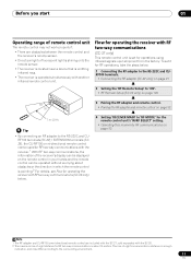
...remote control is pointing.2 For details, see Flow for operating the receiver with the SC-35. 2 The maximum line-of-sight distance for operations using infrared signals upon shipment from the factory. RF100 terminals (SC-37) / EXTENSION terminals (SC35), the CU-RF100 omni-directional remote ...Direct sunlight or fluorescent light is shining onto the remote sensor. • The receiver is located near a device that is emitting infrared rays. • The receiver is operated simultaneously with RF two-way communications (SC-37 only) This remote control unit is set it for RF operations, take the...
...remote control is pointing.2 For details, see Flow for operating the receiver with the SC-35. 2 The maximum line-of-sight distance for operations using infrared signals upon shipment from the factory. RF100 terminals (SC-37) / EXTENSION terminals (SC35), the CU-RF100 omni-directional remote ...Direct sunlight or fluorescent light is shining onto the remote sensor. • The receiver is located near a device that is emitting infrared rays. • The receiver is operated simultaneously with RF two-way communications (SC-37 only) This remote control unit is set it for RF operations, take the...

Owner's Manual
Page 12
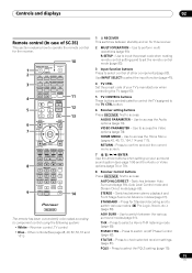
... to the TV operation selector switch. 8 Receiver setting buttons Set the remote control operation selector switch to RECEIVER first to select control of SC-37) This section explains how to operate the remote control for this receiver. 3 MULTI OPERATION Use this receiver, so the AUX button cannot be used.... the current menu screen. 9 ENTER Use the arrow buttons when setting up your surround sound system (see Remote control display on for the receiver. 1 RECEIVER MAIN SOURCE 2 ZONE2 3 3 MULTI OPERATION BDR BD DVD DVR HDMI NET RADIO TV CD HMG ADAPTER 4 USB OPTION iPod TUNER 1...
... to the TV operation selector switch. 8 Receiver setting buttons Set the remote control operation selector switch to RECEIVER first to select control of SC-37) This section explains how to operate the remote control for this receiver. 3 MULTI OPERATION Use this receiver, so the AUX button cannot be used.... the current menu screen. 9 ENTER Use the arrow buttons when setting up your surround sound system (see Remote control display on for the receiver. 1 RECEIVER MAIN SOURCE 2 ZONE2 3 3 MULTI OPERATION BDR BD DVD DVR HDMI NET RADIO TV CD HMG ADAPTER 4 USB OPTION iPod TUNER 1...
Owner's Manual
Page 13
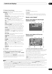
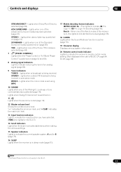
... 1 23 4 56 MAIN IR SOURCE iPod/USB 7 Remote control display for Standard decoding and to access: STATUS - When set to RECEIVER, the receiver can be used to LIGHT MODE 2 (default), the illumination only lights when the remote control LIGHT button is performed, then turns off Phase...Phase Control (page 63). For details, see Using the RF communications function on page 91. • Depending on . Press to check selected receiver settings (page 81). ADV SURR - Press to select a Home THX listening mode (page 60). Switches between Auto Surround (page 59), Auto ...
... 1 23 4 56 MAIN IR SOURCE iPod/USB 7 Remote control display for Standard decoding and to access: STATUS - When set to RECEIVER, the receiver can be used to LIGHT MODE 2 (default), the illumination only lights when the remote control LIGHT button is performed, then turns off Phase...Phase Control (page 63). For details, see Using the RF communications function on page 91. • Depending on . Press to check selected receiver settings (page 81). ADV SURR - Press to select a Home THX listening mode (page 60). Switches between Auto Surround (page 59), Auto ...
Owner's Manual
Page 14
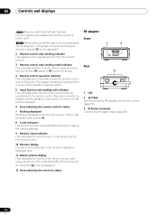
...which operation mode the remote control is currently set to IR. 8 Scroll indicators Light when there are established and the receiver's power is displayed. 12 Area indicating the receiver's status RF adapter Front 1 2 Rear 3 1 LED 2 SETTING Use to . 02 Controls and displays MAIN (Gray... letters): Two-way communications are more selectable items when making the various settings. 9 Receiver input indicator This indicates the input function currently selected for the receiver's zone. 10 Receiver display The same information as an icon and in decibels (dB). When the sound is...
...which operation mode the remote control is currently set to IR. 8 Scroll indicators Light when there are established and the receiver's power is displayed. 12 Area indicating the receiver's status RF adapter Front 1 2 Rear 3 1 LED 2 SETTING Use to . 02 Controls and displays MAIN (Gray... letters): Two-way communications are more selectable items when making the various settings. 9 Receiver input indicator This indicates the input function currently selected for the receiver's zone. 10 Receiver display The same information as an icon and in decibels (dB). When the sound is...
Owner's Manual
Page 15
... modes (2 Pro Logic, Neo:6, etc.) (page 59). Switches between stereo playback and Front Stage Surround Advance modes (page 61). Press to check selected receiver settings (page 81). Press to select a Home THX listening mode (page 60). Use to input the preset code when making remote control settings and to... Direct mode (page 62). ADV SURR - Press to select control of other components (page 83). Controls and displays 02 Remote control (In case of SC-35) This section explains how to access the Home Menu (pages 43, 45, 73, 104, 114 and 117). Use to operate the remote control...
... modes (2 Pro Logic, Neo:6, etc.) (page 59). Switches between stereo playback and Front Stage Surround Advance modes (page 61). Press to check selected receiver settings (page 81). Press to select a Home THX listening mode (page 60). Use to input the preset code when making remote control settings and to... Direct mode (page 62). ADV SURR - Press to select control of other components (page 83). Controls and displays 02 Remote control (In case of SC-35) This section explains how to access the Home Menu (pages 43, 45, 73, 104, 114 and 117). Use to operate the remote control...
Owner's Manual
Page 16
.... Lights during playback of DTS-HD Master Audio signals. 4 MULTI-ZONE Lights when the MULTI-ZONE feature is active (page 79). 5 FULL BAND SC-37 only: Lights when the Full Band Phase Control is being input. Press to select an input signal (page 62). Also use / to ...). Use to perform operations in sleep mode and select the amount of an analog input signal to PCM conversion with SACDs. Switch to put the receiver in the main zone. L/R - Lights with DTS-HD decoding. 96/24 - WMA9 Pro - Lights when the ALC (Auto level control) mode is being...
.... Lights during playback of DTS-HD Master Audio signals. 4 MULTI-ZONE Lights when the MULTI-ZONE feature is active (page 79). 5 FULL BAND SC-37 only: Lights when the Full Band Phase Control is being input. Press to select an input signal (page 62). Also use / to ...). Use to perform operations in sleep mode and select the amount of an analog input signal to PCM conversion with SACDs. Switch to put the receiver in the main zone. L/R - Lights with DTS-HD decoding. 96/24 - WMA9 Pro - Lights when the ALC (Auto level control) mode is being...
Owner's Manual
Page 17
... "+12dB" indicates the maximum level. 13 Input function indicators Light to indicate the input function you have selected. (HMG only lights for the SC-37.) 14 Scroll indicators Light when there are more selectable items when making the various settings. 15 Speaker indicators Lights to the... (page 76). Lights when the mono mode is set to 1.) (SC-37: page 84, SC-35: page 96) Note 1 Full Band Phase Control is only apply to indicate the current speaker system, A and/or B (page 79). 16 SLEEP Lights when the receiver is selected (page 62). Controls and displays 02 STREAM DIRECT -
... "+12dB" indicates the maximum level. 13 Input function indicators Light to indicate the input function you have selected. (HMG only lights for the SC-37.) 14 Scroll indicators Light when there are more selectable items when making the various settings. 15 Speaker indicators Lights to the... (page 76). Lights when the mono mode is set to 1.) (SC-37: page 84, SC-35: page 96) Note 1 Full Band Phase Control is only apply to indicate the current speaker system, A and/or B (page 79). 16 SLEEP Lights when the receiver is selected (page 62). Controls and displays 02 STREAM DIRECT -
Owner's Manual
Page 18
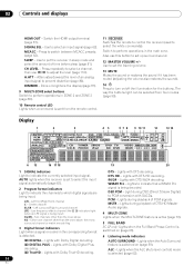
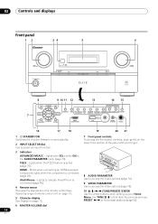
...(TUNE) HOME MENU RETURN HDMI 5 USB VIDEO CAMERA MCACC SETUP MIC PHONES 16 17 18 19 20 21 1 STANDBY/ON Switches the receiver between on and standby. 2 INPUT SELECTOR dial Use to select an input function. 7 Front panel controls To access the front panel controls, push ...) /ENTER Use the arrow buttons when setting up your finger. 3 Indicators ADVANCED MCACC - Lights when EQ is connected (page 40). 4 Remote sensor Receives the signals from the remote control (see Operating range of remote control unit on page 11). 5 Character display See Display on the lower third portion...
...(TUNE) HOME MENU RETURN HDMI 5 USB VIDEO CAMERA MCACC SETUP MIC PHONES 16 17 18 19 20 21 1 STANDBY/ON Switches the receiver between on and standby. 2 INPUT SELECTOR dial Use to select an input function. 7 Front panel controls To access the front panel controls, push ...) /ENTER Use the arrow buttons when setting up your finger. 3 Indicators ADVANCED MCACC - Lights when EQ is connected (page 40). 4 Remote sensor Receives the signals from the remote control (see Operating range of remote control unit on page 11). 5 Character display See Display on the lower third portion...
Owner's Manual
Page 20
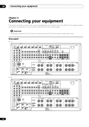
Rear panel SC-37 HDMI BD IN IN 1 IN 2 IN 3 IN 4 OUT 1 (CONTROL) OUT 2...mA MAX) SELECTABLE SEE INSTRUCTION MANUAL SELECTABLE VOIR LE MODE D'EMPLOI CAUTION: SPEAKER IMPEDANCE 6 Ω - 16 Ω . FRONT R CENTER L SC-35 AC IN A HDMI BD IN IN 1 IN 2 IN 3 IN 4 OUT 1 (CONTROL) OUT 2 LAN (10/100) ASSIGNABLE 14 XM...Illustration shows the SC-37, however connections for the SC-35 are the same except where noted. This chapter explains the kinds of components you with many connection possibilities, but it doesn't have to make up your equipment This receiver provides you ...
Rear panel SC-37 HDMI BD IN IN 1 IN 2 IN 3 IN 4 OUT 1 (CONTROL) OUT 2...mA MAX) SELECTABLE SEE INSTRUCTION MANUAL SELECTABLE VOIR LE MODE D'EMPLOI CAUTION: SPEAKER IMPEDANCE 6 Ω - 16 Ω . FRONT R CENTER L SC-35 AC IN A HDMI BD IN IN 1 IN 2 IN 3 IN 4 OUT 1 (CONTROL) OUT 2 LAN (10/100) ASSIGNABLE 14 XM...Illustration shows the SC-37, however connections for the SC-35 are the same except where noted. This chapter explains the kinds of components you with many connection possibilities, but it doesn't have to make up your equipment This receiver provides you ...
Owner's Manual
Page 21
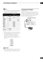
... Setup menu on the receiver. Input function DVD BD TV/SAT DVR/BDR VIDEO HDMI 1 HDMI 2 HDMI 3 HDMI 4 HDMI 5 (front panel) Input Terminals Digital HDMI Component COAX-1 IN 1 (BD) OPT-1 OPT-2 IN 2 OPT-3 IN 3 (HDMI-1) (HDMI-2) (HDMI-3) (HDMI-4) (HDMI-5) CD CD-R/TAPE COAX-2 COAX-3a a.SC-37 only. • SC-35 only: The CU..., switch off the power and disconnect the power cord from the power outlet. Plugging in which the remote control is pointing. Connecting the RF adapter (SC-37 only) Two-way communications between the receiver and remote control are used.
... Setup menu on the receiver. Input function DVD BD TV/SAT DVR/BDR VIDEO HDMI 1 HDMI 2 HDMI 3 HDMI 4 HDMI 5 (front panel) Input Terminals Digital HDMI Component COAX-1 IN 1 (BD) OPT-1 OPT-2 IN 2 OPT-3 IN 3 (HDMI-1) (HDMI-2) (HDMI-3) (HDMI-4) (HDMI-5) CD CD-R/TAPE COAX-2 COAX-3a a.SC-37 only. • SC-35 only: The CU..., switch off the power and disconnect the power cord from the power outlet. Plugging in which the remote control is pointing. Connecting the RF adapter (SC-37 only) Two-way communications between the receiver and remote control are used.
Owner's Manual
Page 24
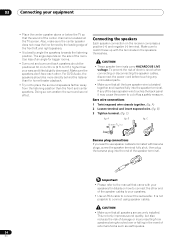
... also reduces the risk of damage or injury resulting from the listening position than your ears and tilted slightly downward. The angle depends on the receiver comprises a positive (+) and negative (-) terminal. A fig. C) fig. C 10 mm (3/8 in the event of the center channel is not possible to use speaker cables terminated with...
... also reduces the risk of damage or injury resulting from the listening position than your ears and tilted slightly downward. The angle depends on the receiver comprises a positive (+) and negative (-) terminal. A fig. C) fig. C 10 mm (3/8 in the event of the center channel is not possible to use speaker cables terminated with...
Owner's Manual
Page 26
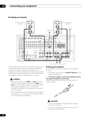
...; Don't connect different speakers from the same terminal in this (having separate terminals for high and low) and the sound improvement will depend on the receiver. Your speakers must be bi-wired if they support biamping. • With these connections, the Speaker System setting makes no difference. • To bi-wire...
...; Don't connect different speakers from the same terminal in this (having separate terminals for high and low) and the sound improvement will depend on the receiver. Your speakers must be bi-wired if they support biamping. • With these connections, the Speaker System setting makes no difference. • To bi-wire...


