
Service Manual
Page 1
... PARTS LIST, ADJUSTMENT, IC INFORMATION etc. P.O. Order No. ARP3355 SCHEMATIC DIAGRAM and PCB CONNECTION DIAGRAM CONTENTS 1. IC INFORMATION 33 PIONEER CORPORATION 4-1, Meguro 1-chome, Meguro-ku, Tokyo 153-8654, Japan PIONEER ELECTRONICS (USA) INC. Box 1760, Long Beach, CA 90801-1760, U.S.A. PIONEER EUROPE NV Haven 1087, Keetberglaan 1, 9120 Melsele, Belgium PIONEER ELECTRONICS ASIACENTRE PTE. Model Type Power Requirement Remarks PRO-507PU KUCXC AC120 V ¶ This service manual should be used...
... PARTS LIST, ADJUSTMENT, IC INFORMATION etc. P.O. Order No. ARP3355 SCHEMATIC DIAGRAM and PCB CONNECTION DIAGRAM CONTENTS 1. IC INFORMATION 33 PIONEER CORPORATION 4-1, Meguro 1-chome, Meguro-ku, Tokyo 153-8654, Japan PIONEER ELECTRONICS (USA) INC. Box 1760, Long Beach, CA 90801-1760, U.S.A. PIONEER EUROPE NV Haven 1087, Keetberglaan 1, 9120 Melsele, Belgium PIONEER ELECTRONICS ASIACENTRE PTE. Model Type Power Requirement Remarks PRO-507PU KUCXC AC120 V ¶ This service manual should be used...
Service Manual
Page 2
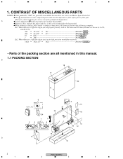
...Parts List. A Screws adjacent to use parts of identical designation. in the following examples. Reference Nos. When ordering resistors, first convert resistance values into code form as in high precision metal film resistors). 5.62k 562 x 101 5621 RN1/4PC 5 6 2 1 F • Parts of the part. Therefore, when replacing...K Ex.2 When there are used for noise filter 23 16 24 7 1 2 5 Speed clamp x3 8 Bead band x3 10 20 12 19 15 D 21 2 PRO-507PU 1 2 3 4 The mark found on product are 3 effective digits (such as shown in the service manual for the base model.
...Parts List. A Screws adjacent to use parts of identical designation. in the following examples. Reference Nos. When ordering resistors, first convert resistance values into code form as in high precision metal film resistors). 5.62k 562 x 101 5621 RN1/4PC 5 6 2 1 F • Parts of the part. Therefore, when replacing...K Ex.2 When there are used for noise filter 23 16 24 7 1 2 5 Speed clamp x3 8 Bead band x3 10 20 12 19 15 D 21 2 PRO-507PU 1 2 3 4 The mark found on product are 3 effective digits (such as shown in the service manual for the base model.
Service Manual
Page 4
... - 29 Function Button Sheet (U) Function Button Sheet (U/E) AAK2895 Not used Not used AAK2903 P13 - 30 P13 - 30 Input Cover Label U Input Cover Label U/E AAX3363 Not used Not used AAX3404 C P15 - 3 P15 - 5 P15 - 5 FRONT SECTION Front Case Assy (507PU) Pioneer Name Plate Elite Badge AMB2917 AAM1098 Not used AMB2918 Not used AWV2311 Refer to the numbers on the " EXPLODED VIEWS ". 4 PRO-507PU 1 2 3 4 PDP-5071PU KUCXC PRO-507PU KUCXC Remarks P23...
... - 29 Function Button Sheet (U) Function Button Sheet (U/E) AAK2895 Not used Not used AAK2903 P13 - 30 P13 - 30 Input Cover Label U Input Cover Label U/E AAX3363 Not used Not used AAX3404 C P15 - 3 P15 - 5 P15 - 5 FRONT SECTION Front Case Assy (507PU) Pioneer Name Plate Elite Badge AMB2917 AAM1098 Not used AMB2918 Not used AWV2311 Refer to the numbers on the " EXPLODED VIEWS ". 4 PRO-507PU 1 2 3 4 PDP-5071PU KUCXC PRO-507PU KUCXC Remarks P23...
Service Manual
Page 6
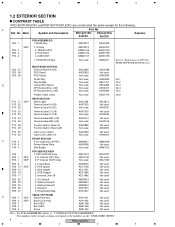
...-lock. 4th pin in IC7803 C Figure A: AWV2311-A /J ADX3484 M17 D CN7802 Figure B: AWV2311-B /J 6 PRO-507PU 1 2 3 4 Or perform the following steps as shown in Figure B. 1 2 3 4 Replacement of AWV2311: HOME NETWORK MODULE ass'y There are two types of HOME NETWORK MODULE ass'y in interface with MAIN ass'y, and only AWV2311-B /J is used in the product, order ADX3484 in addition, and connect...
...-lock. 4th pin in IC7803 C Figure A: AWV2311-A /J ADX3484 M17 D CN7802 Figure B: AWV2311-B /J 6 PRO-507PU 1 2 3 4 Or perform the following steps as shown in Figure B. 1 2 3 4 Replacement of AWV2311: HOME NETWORK MODULE ass'y There are two types of HOME NETWORK MODULE ass'y in interface with MAIN ass'y, and only AWV2311-B /J is used in the product, order ADX3484 in addition, and connect...
Service Manual
Page 7
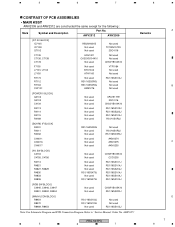
.../16SS220J [MAIN UCOM BLOCK] R8454 R8470 R8469, R8453 RS1/16SS103J RS1/16SS103J Not used Not used Not used RS1/16SS103J Note: For Schematic Diagram and PCB Connection Diagram. ARP3355" Remarks PRO-507PU 5 6 7 8 A B C D 7 Refer to "Service Manual: Order No. 5 6 7 8 CONTRAST OF PCB ASSEMBLIES • MAIN ASSY AWV2309 and AWV2312 are constructed the same except for the following : Mark Symbol and Description Part No.
.../16SS220J [MAIN UCOM BLOCK] R8454 R8470 R8469, R8453 RS1/16SS103J RS1/16SS103J Not used Not used Not used RS1/16SS103J Note: For Schematic Diagram and PCB Connection Diagram. ARP3355" Remarks PRO-507PU 5 6 7 8 A B C D 7 Refer to "Service Manual: Order No. 5 6 7 8 CONTRAST OF PCB ASSEMBLIES • MAIN ASSY AWV2309 and AWV2312 are constructed the same except for the following : Mark Symbol and Description Part No.
Service Manual
Page 8
.../16SS1001F RAB4CQ560J RS1/16SS###J 8 PRO-507PU 1 2 3 4 Refer to " 2.4 - 2.9 Schematic Diagram and 3. AWW1154 AWW1158 Remarks R9200 R9201 RS1/16SS0R0J Not used Not used AKN7008 Note: For Schematic Diagram and PCB Connection Diagram. ARP3355" • POD ASSY AWW1158 and AWW1154 are constructed the same except for the following : A Mark Symbol and Description Part No. Refer to "Service Manual: Order No. PCB Connection Diagram" Mark No. ARP3355" •...
.../16SS1001F RAB4CQ560J RS1/16SS###J 8 PRO-507PU 1 2 3 4 Refer to " 2.4 - 2.9 Schematic Diagram and 3. AWW1154 AWW1158 Remarks R9200 R9201 RS1/16SS0R0J Not used Not used AKN7008 Note: For Schematic Diagram and PCB Connection Diagram. ARP3355" • POD ASSY AWW1158 and AWW1154 are constructed the same except for the following : A Mark Symbol and Description Part No. Refer to "Service Manual: Order No. PCB Connection Diagram" Mark No. ARP3355" •...
Service Manual
Page 10
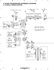
1 2 3 4 2. BLOCK DIAGRAM AND SCHEMATIC DIAGRAM 2.1 OVERALL WIRING DIAGRAM A B C D 10 1 AWV2313- (REGULAR) AWW1156 AWV2310- (ELITE) AWW1153 (REGULAR) AWV2313AWW1157 (ELITE) AWV2310AWW1155 PRO-507PU 2 3 4
1 2 3 4 2. BLOCK DIAGRAM AND SCHEMATIC DIAGRAM 2.1 OVERALL WIRING DIAGRAM A B C D 10 1 AWV2313- (REGULAR) AWW1156 AWV2310- (ELITE) AWW1153 (REGULAR) AWV2313AWW1157 (ELITE) AWV2310AWW1155 PRO-507PU 2 3 4
Service Manual
Page 12
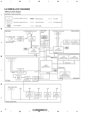
... [Digital Media Processor] Peripheral bus IC7857 C TC74LCX125 Reset [3-state Buffer] Tx / Rx I/O block IC7852 TC7S00F [NAND] IC7851 PST596IN [Reset IC] IC7852 TC74LCX04 [Inverter] Reset 27MHz X'tal IC7703 AGC1027-A-PI (S29GL128N90TFIR2) [Flash Memory (128Mbit)] Reset DDR block +5V for USB Bus-power *CN7802 * Or, a wire is soldered IC7803 R5520H001B [USB High-side Switch] +5V L7801 ATH7015[C. IC] IC7901 LM2664M6X [Converter IC] 12 PRO-507PU...
... [Digital Media Processor] Peripheral bus IC7857 C TC74LCX125 Reset [3-state Buffer] Tx / Rx I/O block IC7852 TC7S00F [NAND] IC7851 PST596IN [Reset IC] IC7852 TC74LCX04 [Inverter] Reset 27MHz X'tal IC7703 AGC1027-A-PI (S29GL128N90TFIR2) [Flash Memory (128Mbit)] Reset DDR block +5V for USB Bus-power *CN7802 * Or, a wire is soldered IC7803 R5520H001B [USB High-side Switch] +5V L7801 ATH7015[C. IC] IC7901 LM2664M6X [Converter IC] 12 PRO-507PU...
Service Manual
Page 13
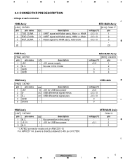
... connection in this model - - USB cable voltage (V) +5.0 +3.3 / 0 +3.3 / 0 0 C 0 HNM Ass'y [HN7] CN7802* pin pin name 1 N.C. 2 +5.1V 3 N.C. No use in AWV2311-B. For AWV2311-A, a wire is directly soldered to 4th pin of IC78.03 MTB MAIN Ass'y CN4011 voltage (V) pin - 1 +5.1 2 - 3 D PRO-507PU 13 5 6 7 8 HNM Ass'y A MTB MAIN Ass'y [HN1] CN7851 [M14] CN4017 pin pin name I/O description voltage (V) pin 1 TXD_DLNA I UART signal...
... connection in this model - - USB cable voltage (V) +5.0 +3.3 / 0 +3.3 / 0 0 C 0 HNM Ass'y [HN7] CN7802* pin pin name 1 N.C. 2 +5.1V 3 N.C. No use in AWV2311-B. For AWV2311-A, a wire is directly soldered to 4th pin of IC78.03 MTB MAIN Ass'y CN4011 voltage (V) pin - 1 +5.1 2 - 3 D PRO-507PU 13 5 6 7 8 HNM Ass'y A MTB MAIN Ass'y [HN1] CN7851 [M14] CN4017 pin pin name I/O description voltage (V) pin 1 TXD_DLNA I UART signal...
Service Manual
Page 23
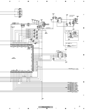
5 6 7 8 A USB POWER SECTION B C D PRO-507PU 23 5 6 7 8
5 6 7 8 A USB POWER SECTION B C D PRO-507PU 23 5 6 7 8
Service Manual
Page 28
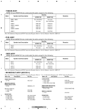
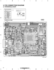
... CONNECTION DIAGRAM 3.1 HN MODULE ASSY A NOTE FOR PCB DIAGRAMS : 1. The parts mounted on this PCB include all necessary parts for respective destinations, be sure to check with resistor DGS D G SD G S Field effect transistor P.C.Board Chip Part SIDE B Resistor array 3-terminal regulator • HN MODULE ASSY B 4 SIDE A C D 28 1 PRO-507PU 2 3 (ANP2148B) 4 Part numbers in PCB diagrams match those in the schematic diagrams. 2. A comparison between the main parts...
... CONNECTION DIAGRAM 3.1 HN MODULE ASSY A NOTE FOR PCB DIAGRAMS : 1. The parts mounted on this PCB include all necessary parts for respective destinations, be sure to check with resistor DGS D G SD G S Field effect transistor P.C.Board Chip Part SIDE B Resistor array 3-terminal regulator • HN MODULE ASSY B 4 SIDE A C D 28 1 PRO-507PU 2 3 (ANP2148B) 4 Part numbers in PCB diagrams match those in the schematic diagrams. 2. A comparison between the main parts...
Service Manual
Page 30
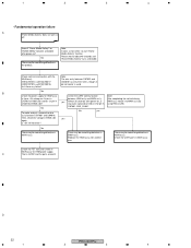
... the network server been turned on and connected to use the number which can not be played though it needs to the sheet of PDP. If the contents can be selected? All " 0 " and all " 1 " in " Network yes Setup " menu to PDP with another one . When the PDP is directly connected to a used . Note: Confirm that the server does not support WMV. Below is used in the server displayed...
... the network server been turned on and connected to use the number which can not be played though it needs to the sheet of PDP. If the contents can be selected? All " 0 " and all " 1 " in " Network yes Setup " menu to PDP with another one . When the PDP is directly connected to a used . Note: Confirm that the server does not support WMV. Below is used in the server displayed...
Service Manual
Page 31
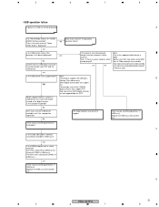
... files of the CANON digital cameras only support PTP. A Can "Home Media Gallery" on "HOME MENU" GUI be displayed! Refer to CN4011 in HNM ass'y? yes No Confirm that the USB cable is used as a USB device, try other end is attached to the sheet of the supported video format is correctly inserted into both side: PDP and the USB device. yes No Note...
... files of the CANON digital cameras only support PTP. A Can "Home Media Gallery" on "HOME MENU" GUI be displayed! Refer to CN4011 in HNM ass'y? yes No Confirm that the USB cable is used as a USB device, try other end is attached to the sheet of the supported video format is correctly inserted into both side: PDP and the USB device. yes No Note...
Service Manual
Page 32
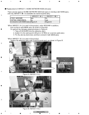
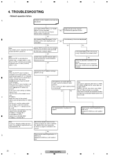
...PRO-507PU 1 2 3 4 No B Check the power supply for HNM power supply. No To make analysis, remove the wire No yes ass'y between CN7901 and CN4016 has only three wires, though 4pin connector is used. There may be something defective in MAIN ass'y. C That is HNM ass'y notice it . Please wait for about 40 seconds until "Home Media Gallery" turns... each wire connection with another one. 1 2 3 4 • Fundamental operation failure A "Home Media Gallery" does not work at all! Doesn't "Home Media Gallery" on "HOME MENU" become selectable after power-on ? ...
...PRO-507PU 1 2 3 4 No B Check the power supply for HNM power supply. No To make analysis, remove the wire No yes ass'y between CN7901 and CN4016 has only three wires, though 4pin connector is used. There may be something defective in MAIN ass'y. C That is HNM ass'y notice it . Please wait for about 40 seconds until "Home Media Gallery" turns... each wire connection with another one. 1 2 3 4 • Fundamental operation failure A "Home Media Gallery" does not work at all! Doesn't "Home Media Gallery" on "HOME MENU" become selectable after power-on ? ...
Service Manual
Page 33
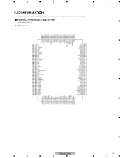
5 6 7 5. IC INFORMATION • The information shown in the list is basic information and may not correspond exactly to that shown in the schematic diagrams. RTL8100CL-LF (HN MODULE Assy: IC7754) • Ethernet Controller IC Pin Arrangement 8 A B C D PRO-507PU 33 5 6 7 8
5 6 7 5. IC INFORMATION • The information shown in the list is basic information and may not correspond exactly to that shown in the schematic diagrams. RTL8100CL-LF (HN MODULE Assy: IC7754) • Ethernet Controller IC Pin Arrangement 8 A B C D PRO-507PU 33 5 6 7 8


