
Service Manual
Page 1
..., EXPLODED VIEWS AND PARTS LIST, BLOCK DIAGRAM, PCB PARTS LIST, ADJUSTMENT, IC INFORMATION etc. TROUBLESHOOTING 30 5. PIONEER EUROPE NV Haven 1087, Keetberglaan 1, 9120 Melsele, Belgium PIONEER ELECTRONICS ASIACENTRE PTE. ...PIONEER ELECTRONICS (USA) INC. BLOCK DIAGRAM AND SCHEMATIC DIAGRAM 10 2.1 OVERALL WIRING DIAGRAM 10 2.2 HNM BLOCK DIAGRAM 12 2.3 CONNECTOR PIN DESCRIPTION 13 2.4 HN MODULE ASSY (1/6 14 2.5 HN MODULE ASSY (2/6 18 2.6 HN MODULE ASSY (3/6 20 2.7 HN MODULE ASSY (4/6 22 2.8 HN MODULE ASSY (5/6 24 2.9 HN MODULE ASSY (6/6 26 3. ARP3399 PLASMA DISPLAY PRO-507PU...
..., EXPLODED VIEWS AND PARTS LIST, BLOCK DIAGRAM, PCB PARTS LIST, ADJUSTMENT, IC INFORMATION etc. TROUBLESHOOTING 30 5. PIONEER EUROPE NV Haven 1087, Keetberglaan 1, 9120 Melsele, Belgium PIONEER ELECTRONICS ASIACENTRE PTE. ...PIONEER ELECTRONICS (USA) INC. BLOCK DIAGRAM AND SCHEMATIC DIAGRAM 10 2.1 OVERALL WIRING DIAGRAM 10 2.2 HNM BLOCK DIAGRAM 12 2.3 CONNECTOR PIN DESCRIPTION 13 2.4 HN MODULE ASSY (1/6 14 2.5 HN MODULE ASSY (2/6 18 2.6 HN MODULE ASSY (3/6 20 2.7 HN MODULE ASSY (4/6 22 2.8 HN MODULE ASSY (5/6 24 2.9 HN MODULE ASSY (6/6 26 3. ARP3399 PLASMA DISPLAY PRO-507PU...
Service Manual
Page 2
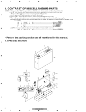
... 4 7 3 J 0.5 R50 RN2H R 5 0 K 1 1R0 RS1P 1 R 0 K Ex.2 When there are 3 effective digits (such as in high precision metal film resistors). 5.62k 562 x 101 5621 RN1/4PC 5 6 2 1 F • Parts of the packing section are not in the service manual for disassembly. Therefore, when replacing, be sure to mark on some component... for antenna cable 13 9, 11, 14 Binder for noise filter 23 16 24 7 1 2 5 Speed clamp x3 8 Bead band x3 10 20 12 19 15 D 21 2 PRO-507PU 1 2 3 4 A Screws adjacent to use parts of the...
... 4 7 3 J 0.5 R50 RN2H R 5 0 K 1 1R0 RS1P 1 R 0 K Ex.2 When there are 3 effective digits (such as in high precision metal film resistors). 5.62k 562 x 101 5621 RN1/4PC 5 6 2 1 F • Parts of the packing section are not in the service manual for disassembly. Therefore, when replacing, be sure to mark on some component... for antenna cable 13 9, 11, 14 Binder for noise filter 23 16 24 7 1 2 5 Speed clamp x3 8 Bead band x3 10 20 12 19 15 D 21 2 PRO-507PU 1 2 3 4 A Screws adjacent to use parts of the...
Service Manual
Page 4
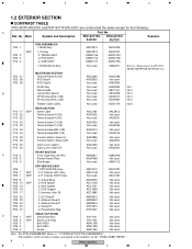
Chassis (507) Assy 2..P. 1 2 3 4 1.2 EXTERIOR SECTION CONTRAST TABLE PRO-507PU/KUCXC and PDP-5071PU/KUCXC are constructed the same except for the following : A Ref. Mark Symbol and Description Part No. Chassis (507E) Assy AWU1212 AWU1148 Not used AWU1227 Not used AWU1187 P25 - 8 P25 - 10 P25 - 13...Label U Input Cover Label U/E AAX3363 Not used Not used AAX3404 C P15 - 3 P15 - 5 P15 - 5 FRONT SECTION Front Case Assy (507PU) Pioneer Name Plate Elite Badge AMB2917 AAM1098 Not used AMB2918 Not used Note : For PCB ASSEMBLIES, Refer to " CONTRAST OF PCB ASSEMBLIES ". : The ...
Chassis (507) Assy 2..P. 1 2 3 4 1.2 EXTERIOR SECTION CONTRAST TABLE PRO-507PU/KUCXC and PDP-5071PU/KUCXC are constructed the same except for the following : A Ref. Mark Symbol and Description Part No. Chassis (507E) Assy AWU1212 AWU1148 Not used AWU1227 Not used AWU1187 P25 - 8 P25 - 10 P25 - 13...Label U Input Cover Label U/E AAX3363 Not used Not used AAX3404 C P15 - 3 P15 - 5 P15 - 5 FRONT SECTION Front Case Assy (507PU) Pioneer Name Plate Elite Badge AMB2917 AAM1098 Not used AMB2918 Not used Note : For PCB ASSEMBLIES, Refer to " CONTRAST OF PCB ASSEMBLIES ". : The ...
Service Manual
Page 6
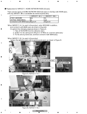
...in Figure A. 1. Or perform the following steps as shown in Figure B. A AWV2311- Solder it with MAIN ass'y When AWV2311-B /J is available as a service parts ass'y. 1 2 3 4 Replacement of AWV2311: HOME NETWORK MODULE ass'y There are two types of HOME NETWORK MODULE ass'y in interface with MAIN ass'y as shown ... in addition, and connect it with MAIN ass'y, and only AWV2311-B /J is used in the product, replace the defective ass'y with a service parts ass'y as shown in IC7803 C Figure A: AWV2311-A /J ADX3484 M17 D CN7802 Figure B: AWV2311-B /J 6 PRO-507PU 1 2 3 4
...in Figure A. 1. Or perform the following steps as shown in Figure B. A AWV2311- Solder it with MAIN ass'y When AWV2311-B /J is available as a service parts ass'y. 1 2 3 4 Replacement of AWV2311: HOME NETWORK MODULE ass'y There are two types of HOME NETWORK MODULE ass'y in interface with MAIN ass'y as shown ... in addition, and connect it with MAIN ass'y, and only AWV2311-B /J is used in the product, replace the defective ass'y with a service parts ass'y as shown in IC7803 C Figure A: AWV2311-A /J ADX3484 M17 D CN7802 Figure B: AWV2311-B /J 6 PRO-507PU 1 2 3 4
Service Manual
Page 7
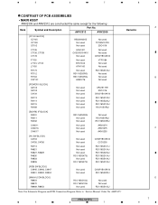
... Manual: Order No. 5 6 7 8 CONTRAST OF PCB ASSEMBLIES • MAIN ASSY AWV2309 and AWV2312 are constructed the same except for the following : Mark Symbol and Description Part No. AWV2312 AWV2309 [DT AV BLOCK] IC7105 IC7108 Q7102 R5520H001B Not used Not used Not used TC7WH157FU 2SC4116 C7135 C7136, C7138 C7178 ACH1421 CKSSYB104K10 Not... R8470 R8469, R8453 RS1/16SS103J RS1/16SS103J Not used Not used Not used RS1/16SS103J Note: For Schematic Diagram and PCB Connection Diagram. ARP3355" Remarks PRO-507PU 5 6 7 8 A B C D 7
... Manual: Order No. 5 6 7 8 CONTRAST OF PCB ASSEMBLIES • MAIN ASSY AWV2309 and AWV2312 are constructed the same except for the following : Mark Symbol and Description Part No. AWV2312 AWV2309 [DT AV BLOCK] IC7105 IC7108 Q7102 R5520H001B Not used Not used Not used TC7WH157FU 2SC4116 C7135 C7136, C7138 C7178 ACH1421 CKSSYB104K10 Not... R8470 R8469, R8453 RS1/16SS103J RS1/16SS103J Not used Not used Not used RS1/16SS103J Note: For Schematic Diagram and PCB Connection Diagram. ARP3355" Remarks PRO-507PU 5 6 7 8 A B C D 7
Service Manual
Page 8
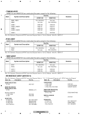
...used Not used AKN7008 Note: For Schematic Diagram and PCB Connection Diagram. Refer to "Service Manual: Order No. Description Part No. AWW1154 AWW1158 Remarks R9200 R9201 RS1/16SS0R0J Not used Not used RS1/16SS0R0J Note: For Schematic Diagram and PCB ...IC7701,7702 MISCELLANEOUS F 7701 RESISTORS R 7709,7710 R 7711-7718 Other Resistors DCH1201 CCSSCH7R0D50 CKSSYF104Z16 EDD2516AKTA-6B ATL7002 RS1/16SS1001F RAB4CQ560J RS1/16SS###J 8 PRO-507PU 1 2 3 4 Refer to "Service Manual: Order No. ARP3355" • SIDE ASSY AWW1155 and AWW1157 are constructed the same except for ...
...used Not used AKN7008 Note: For Schematic Diagram and PCB Connection Diagram. Refer to "Service Manual: Order No. Description Part No. AWW1154 AWW1158 Remarks R9200 R9201 RS1/16SS0R0J Not used Not used RS1/16SS0R0J Note: For Schematic Diagram and PCB ...IC7701,7702 MISCELLANEOUS F 7701 RESISTORS R 7709,7710 R 7711-7718 Other Resistors DCH1201 CCSSCH7R0D50 CKSSYF104Z16 EDD2516AKTA-6B ATL7002 RS1/16SS1001F RAB4CQ560J RS1/16SS###J 8 PRO-507PU 1 2 3 4 Refer to "Service Manual: Order No. ARP3355" • SIDE ASSY AWW1155 and AWW1157 are constructed the same except for ...
Service Manual
Page 28
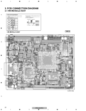
...diagrams is shown below. PCB CONNECTION DIAGRAM 3.1 HN MODULE ASSY A NOTE FOR PCB DIAGRAMS : 1. A comparison between the main parts of PCB diagrams. Connector Capacitor BCE Transistor B C EB C E SIDE A BCE Transistor with the schematic diagram. 4. Symbol In ...Part Name 3. The parts mounted on this PCB include all necessary parts for respective destinations, be sure to check with resistor DGS D G SD G S Field effect transistor P.C.Board Chip Part SIDE B Resistor array 3-terminal regulator • HN MODULE ASSY B 4 SIDE A C D 28 1 PRO-507PU 2 3 (ANP2148B) 4 Part...
...diagrams is shown below. PCB CONNECTION DIAGRAM 3.1 HN MODULE ASSY A NOTE FOR PCB DIAGRAMS : 1. A comparison between the main parts of PCB diagrams. Connector Capacitor BCE Transistor B C EB C E SIDE A BCE Transistor with the schematic diagram. 4. Symbol In ...Part Name 3. The parts mounted on this PCB include all necessary parts for respective destinations, be sure to check with resistor DGS D G SD G S Field effect transistor P.C.Board Chip Part SIDE B Resistor array 3-terminal regulator • HN MODULE ASSY B 4 SIDE A C D 28 1 PRO-507PU 2 3 (ANP2148B) 4 Part...
Service Manual
Page 30
... menu of 720p resolution are available. In this case, make settings as the network server uses. An example for the network address part designated by yourself. yes yes No Note: The network server should be selected? Most of PDP. Then, is used in HNM ass...both network hub, a straight cable is there any register restriction in the server surely shared with another IP Address: 192.168.201.1 one . 30 PRO-507PU 1 2 3 4 Below is properly set an appropriate IP address by the Subnet mask. Subnet mask: 255.255.255.0 Replace the HNM ass'y...
... menu of 720p resolution are available. In this case, make settings as the network server uses. An example for the network address part designated by yourself. yes yes No Note: The network server should be selected? Most of PDP. Then, is used in HNM ass...both network hub, a straight cable is there any register restriction in the server surely shared with another IP Address: 192.168.201.1 one . 30 PRO-507PU 1 2 3 4 Below is properly set an appropriate IP address by the Subnet mask. Subnet mask: 255.255.255.0 Replace the HNM ass'y...
Service Manual
Page 32
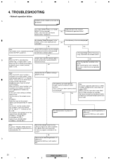
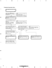
... To make analysis, remove the wire No yes ass'y between HNM ass'y and MAIN ass'y. Check the UART path in MAIN side yes again. D 32 PRO-507PU 1 2 3 4 No B Check the power supply for HNM ass'y. CN7851: RXD_DLNA? No There may be something defective in the product. Note: The ...wire ass'y between CN7901 and CN4016 has only three wires, though 4pin connector is Q4102 and the parts around it to start "Home Media Gallery" function. Replace the HNM ass'y with the MAIN ass'y. [HN1]CN7851[M14]CN4017 [HN2]CN7901[...
... To make analysis, remove the wire No yes ass'y between HNM ass'y and MAIN ass'y. Check the UART path in MAIN side yes again. D 32 PRO-507PU 1 2 3 4 No B Check the power supply for HNM ass'y. CN7851: RXD_DLNA? No There may be something defective in the product. Note: The ...wire ass'y between CN7901 and CN4016 has only three wires, though 4pin connector is Q4102 and the parts around it to start "Home Media Gallery" function. Replace the HNM ass'y with the MAIN ass'y. [HN1]CN7851[M14]CN4017 [HN2]CN7901[...


