
Service Manual
Page 7
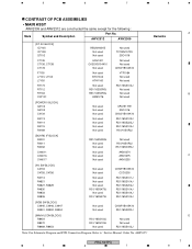
5 6 7 8 CONTRAST OF PCB ASSEMBLIES • MAIN ASSY AWV2309 and AWV2312 are constructed the same except for the following : Mark ...Not used Not used Not used Not used UPA1917TE 2SC4116 CKSSYB104K10 RS1/16SS102J RS1/16SS223J RS1/16SS104J RS1/10S0R0J [BOARD IF BLOCK] R4031 R4011 R4032 CN4011 CN4016 CN4017 RS1/16SS0R0J Not used Not used Not used Not used ...RS1/16SS104J [RGB SW BLOCK] C4945, C4946, C4947 R4901, R4902, R4904 Not used Not used CKSRYB105K10 RS1/16SS220J [MAIN UCOM BLOCK] R8454 R8470 R8469, R8453 RS1/16SS103J RS1/16SS103J Not used Not used Not used RS1/16SS103J Note: ...
5 6 7 8 CONTRAST OF PCB ASSEMBLIES • MAIN ASSY AWV2309 and AWV2312 are constructed the same except for the following : Mark ...Not used Not used Not used Not used UPA1917TE 2SC4116 CKSSYB104K10 RS1/16SS102J RS1/16SS223J RS1/16SS104J RS1/10S0R0J [BOARD IF BLOCK] R4031 R4011 R4032 CN4011 CN4016 CN4017 RS1/16SS0R0J Not used Not used Not used Not used ...RS1/16SS104J [RGB SW BLOCK] C4945, C4946, C4947 R4901, R4902, R4904 Not used Not used CKSRYB105K10 RS1/16SS220J [MAIN UCOM BLOCK] R8454 R8470 R8469, R8453 RS1/16SS103J RS1/16SS103J Not used Not used Not used RS1/16SS103J Note: ...
Service Manual
Page 28
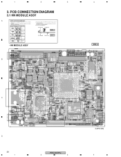
...PCB Diagrams Symbol In Schematic Diagrams B C EB C E Part Name 3. For further information for several destinations. A comparison between the main parts of PCB diagrams. Connector Capacitor BCE Transistor B C EB C E SIDE A BCE Transistor with the schematic diagram. 4. 1 ... destinations, be sure to check with resistor DGS D G SD G S Field effect transistor P.C.Board Chip Part SIDE B Resistor array 3-terminal regulator • HN MODULE ASSY B 4 SIDE A C D 28 1 PRO-507PU 2 3 (ANP2148B) 4 PCB CONNECTION DIAGRAM 3.1 HN MODULE ASSY A NOTE FOR PCB DIAGRAMS : ...
...PCB Diagrams Symbol In Schematic Diagrams B C EB C E Part Name 3. For further information for several destinations. A comparison between the main parts of PCB diagrams. Connector Capacitor BCE Transistor B C EB C E SIDE A BCE Transistor with the schematic diagram. 4. 1 ... destinations, be sure to check with resistor DGS D G SD G S Field effect transistor P.C.Board Chip Part SIDE B Resistor array 3-terminal regulator • HN MODULE ASSY B 4 SIDE A C D 28 1 PRO-507PU 2 3 (ANP2148B) 4 PCB CONNECTION DIAGRAM 3.1 HN MODULE ASSY A NOTE FOR PCB DIAGRAMS : ...


