
Service Manual
Page 1
... 1. PCB CONNECTION DIAGRAM 28 3.1 HN MODULE ASSY 28 4. IC INFORMATION 33 PIONEER CORPORATION 4-1, Meguro 1-chome, Meguro-ku, Tokyo 153-8654, Japan PIONEER ELECTRONICS (USA) INC. Model Type Power Requirement Remarks PRO-507PU KUCXC AC120 V ¶ This service manual should be used together with the following manual(s): Model No. CONTRAST OF MISCELLANEOUS PARTS 2 2. BLOCK DIAGRAM AND SCHEMATIC DIAGRAM...
... 1. PCB CONNECTION DIAGRAM 28 3.1 HN MODULE ASSY 28 4. IC INFORMATION 33 PIONEER CORPORATION 4-1, Meguro 1-chome, Meguro-ku, Tokyo 153-8654, Japan PIONEER ELECTRONICS (USA) INC. Model Type Power Requirement Remarks PRO-507PU KUCXC AC120 V ¶ This service manual should be used together with the following manual(s): Model No. CONTRAST OF MISCELLANEOUS PARTS 2 2. BLOCK DIAGRAM AND SCHEMATIC DIAGRAM...
Service Manual
Page 2
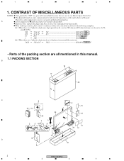
... to mark on some component parts indicates the importance of the safety factor of the packing section are 3 effective digits (such as shown in this manual. 1.1 PACKING SECTION B 18 17 22 C 6 4 3 Noise filter for antenna cable 13 9, 11, 14 Binder for disassembly. Ex.1 When there are 2 ... they are used for noise filter 23 16 24 7 1 2 5 Speed clamp x3 8 Bead band x3 10 20 12 19 15 D 21 2 PRO-507PU 1 2 3 4 The mark found on product are not in the service manual for the base model. in our Master Spare Parts List. Reference Nos. 1 2 3 4 1.
... to mark on some component parts indicates the importance of the safety factor of the packing section are 3 effective digits (such as shown in this manual. 1.1 PACKING SECTION B 18 17 22 C 6 4 3 Noise filter for antenna cable 13 9, 11, 14 Binder for disassembly. Ex.1 When there are 2 ... they are used for noise filter 23 16 24 7 1 2 5 Speed clamp x3 8 Bead band x3 10 20 12 19 15 D 21 2 PRO-507PU 1 2 3 4 The mark found on product are not in the service manual for the base model. in our Master Spare Parts List. Reference Nos. 1 2 3 4 1.
Service Manual
Page 7
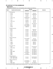
... R8470 R8469, R8453 RS1/16SS103J RS1/16SS103J Not used Not used Not used RS1/16SS103J Note: For Schematic Diagram and PCB Connection Diagram. Refer to "Service Manual: Order No. 5 6 7 8 CONTRAST OF PCB ASSEMBLIES • MAIN ASSY AWV2309 and AWV2312 are constructed the same except for the following : Mark Symbol and Description Part...
... R8470 R8469, R8453 RS1/16SS103J RS1/16SS103J Not used Not used Not used RS1/16SS103J Note: For Schematic Diagram and PCB Connection Diagram. Refer to "Service Manual: Order No. 5 6 7 8 CONTRAST OF PCB ASSEMBLIES • MAIN ASSY AWV2309 and AWV2312 are constructed the same except for the following : Mark Symbol and Description Part...
Service Manual
Page 8
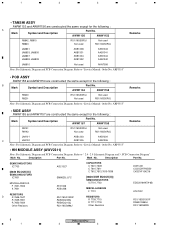
...JA9101 AKB1303 AKB1304 C JA9102 AKB1305 AKB1306 Note: For Schematic Diagram and PCB Connection Diagram. Refer to "Service Manual: Order No. PCB Connection Diagram" Mark No. SEMICONDUCTORS IC7703 [8620 BLOCK(U)] SEMICONDUCTORS IC7601 MISCELLANEOUS F ...PRO-507PU 1 2 3 4 AWW1157 AWW1155 R9141 R9142 RS1/16SS0R0J Not used Not used RS1/16SS0R0J Note: For Schematic Diagram and PCB Connection Diagram. ARP3355" • SIDE ASSY AWW1155 and AWW1157 are constructed the same except for the following : A Mark Symbol and Description Part No. Refer to "Service Manual...
...JA9101 AKB1303 AKB1304 C JA9102 AKB1305 AKB1306 Note: For Schematic Diagram and PCB Connection Diagram. Refer to "Service Manual: Order No. PCB Connection Diagram" Mark No. SEMICONDUCTORS IC7703 [8620 BLOCK(U)] SEMICONDUCTORS IC7601 MISCELLANEOUS F ...PRO-507PU 1 2 3 4 AWW1157 AWW1155 R9141 R9142 RS1/16SS0R0J Not used Not used RS1/16SS0R0J Note: For Schematic Diagram and PCB Connection Diagram. ARP3355" • SIDE ASSY AWW1155 and AWW1157 are constructed the same except for the following : A Mark Symbol and Description Part No. Refer to "Service Manual...


