
Functional Instructions
Page 1
PT-DZ6710 PT-DZ6700 PT-DW6300 PT-D6000 The information of these instructions are shared use with multiple models of DZ6710 series, DZ6700 series, DW6300 series and D6000 series. TQBJ0299 ENGLISH Functional Instructions DLP™Based Projector Commercial Use Model No.
PT-DZ6710 PT-DZ6700 PT-DW6300 PT-D6000 The information of these instructions are shared use with multiple models of DZ6710 series, DZ6700 series, DW6300 series and D6000 series. TQBJ0299 ENGLISH Functional Instructions DLP™Based Projector Commercial Use Model No.
Functional Instructions
Page 2
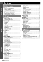
...Started Setting up 3 Screen size and throw distance 3 Geometric adjustment 8 Front leg adjusters and throwing angle 9 Connections 10 Before connection to the projector 10 Pin assignments and signal names 10 Connecting example: Computers 11 Connecting example: AV equipment 11 Settings Menu Navigation 12 Main menu and Sub-...DVI-D IN 26 SDI IN 26 ON-SCREEN DISPLAY 26 BACK COLOR 27 STARTUP LOGO 27 FREEZE 27 SIDE BY SIDE 27 PROJECTOR SETUP menu 28 PROJECTOR ID 28 INSTALLATION 28 HIGH ALTITUDE MODE 28 COOLING CONDITION 28 LAMP SELECT 29 LAMP RELAY 29 ENGLISH - 2 LAMP POWER 29...
...Started Setting up 3 Screen size and throw distance 3 Geometric adjustment 8 Front leg adjusters and throwing angle 9 Connections 10 Before connection to the projector 10 Pin assignments and signal names 10 Connecting example: Computers 11 Connecting example: AV equipment 11 Settings Menu Navigation 12 Main menu and Sub-...DVI-D IN 26 SDI IN 26 ON-SCREEN DISPLAY 26 BACK COLOR 27 STARTUP LOGO 27 FREEZE 27 SIDE BY SIDE 27 PROJECTOR SETUP menu 28 PROJECTOR ID 28 INSTALLATION 28 HIGH ALTITUDE MODE 28 COOLING CONDITION 28 LAMP SELECT 29 LAMP RELAY 29 ENGLISH - 2 LAMP POWER 29...
Functional Instructions
Page 3
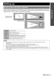
...the powered zoom lens and lens shifting mechanism. SH Getting Started Setting up Screen size and throw distance When planning the projector and screen geometry, refer to the figures below and the information on the following measurements and the calculation results are used when... DLP projectors are approximate and may differ slightly from the actual measurements. • The throw ratio is based on to the lens can be finely adjusted with the projector. • Special care should be used in which case there...
...the powered zoom lens and lens shifting mechanism. SH Getting Started Setting up Screen size and throw distance When planning the projector and screen geometry, refer to the figures below and the information on the following measurements and the calculation results are used when... DLP projectors are approximate and may differ slightly from the actual measurements. • The throw ratio is based on to the lens can be finely adjusted with the projector. • Special care should be used in which case there...
Functional Instructions
Page 9
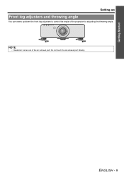
Do not touch the air exhaust port directly. ENGLISH - 9 Getting Started Setting up Front leg adjusters and throwing angle You can screw up/down the front leg adjusters to control the angle of the air exhaust port. STANDBY(RED)/ ON(GREEN) LAMP TEMP FILTER NOTE: • Heated air comes out of the projector for adjusting the throwing angle.
Do not touch the air exhaust port directly. ENGLISH - 9 Getting Started Setting up Front leg adjusters and throwing angle You can screw up/down the front leg adjusters to control the angle of the air exhaust port. STANDBY(RED)/ ON(GREEN) LAMP TEMP FILTER NOTE: • Heated air comes out of the projector for adjusting the throwing angle.
Functional Instructions
Page 10
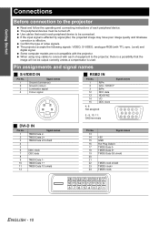
... jitter, the projected image may have poor image quality and timebase correction is used. Confirm the type of each peripheral device to the projector Read and follow the operating and connecting instructions of video signals. Pin assignments and signal names J S-VIDEO IN Pin No. 1 2...compensator is effective. Level) and digital signal. ENGLISH - 10 When using long cables to connect with each of equipment to the projector, there is a possibility that match each peripheral device. Getting Started Connections Before connection to be connected. Use cables that the ...
... jitter, the projected image may have poor image quality and timebase correction is used. Confirm the type of each peripheral device to the projector Read and follow the operating and connecting instructions of video signals. Pin assignments and signal names J S-VIDEO IN Pin No. 1 2...compensator is effective. Level) and digital signal. ENGLISH - 10 When using long cables to connect with each of equipment to the projector, there is a possibility that match each peripheral device. Getting Started Connections Before connection to be connected. Use cables that the ...
Functional Instructions
Page 11
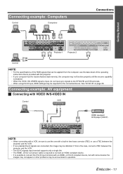
...IN/S-VIDEO IN Control VCR HDMI equipped DVD player (HDCP) NOTE: • When connecting with a VCR, be sure to use a TBC between the projector and the VCR. • The DVI-D signals input terminal supports only a single link. • The HDMI - If this is the case, ...; If non-standard burst signals are connected, the image may be distorted. ENGLISH - 11 Connecting example: Computers Control Computers Connections Getting Started Projector 1 Projector 2 Control NOTE: • For the specifications of the RGB signals that can be applied from the computer, see the data sheet of ...
...IN/S-VIDEO IN Control VCR HDMI equipped DVD player (HDCP) NOTE: • When connecting with a VCR, be sure to use a TBC between the projector and the VCR. • The DVI-D signals input terminal supports only a single link. • The HDMI - If this is the case, ...; If non-standard burst signals are connected, the image may be distorted. ENGLISH - 11 Connecting example: Computers Control Computers Connections Getting Started Projector 1 Projector 2 Control NOTE: • For the specifications of the RGB signals that can be applied from the computer, see the data sheet of ...
Functional Instructions
Page 13
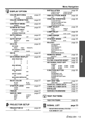
... 25 page 25 page 25 page 25 page 25 page 26 page 26 page 26 page 26 page 27 page 27 page 27 page 27 PROJECTOR SETUP PROJECTOR ID ALL 1 - 64 page 28 Menu Navigation INSTALLATION page 28 FRONT/FLOOR FRONT/CEILING REAR/FLOOR REAR/CEILING HIGH ALTITUDE MODE page 28 OFF...
... 25 page 25 page 25 page 25 page 25 page 26 page 26 page 26 page 26 page 27 page 27 page 27 page 27 PROJECTOR SETUP PROJECTOR ID ALL 1 - 64 page 28 Menu Navigation INSTALLATION page 28 FRONT/FLOOR FRONT/CEILING REAR/FLOOR REAR/CEILING HIGH ALTITUDE MODE page 28 OFF...
Functional Instructions
Page 15
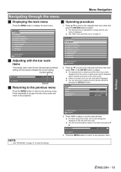
J Operating procedure 1. MAIN MENU PICTURE POSITION ADVANCED MENU DISPLAY LANGUAGE DISPLAY OPTION PROJECTOR SETUP TEST PATTERN SIGNAL LIST SECURITY NETWORK MENU SELECT ENTER SUB MENU 2. Called up and the other menu items disappear from the menu mode and ... highlighted in orange and the submenu is a lower level, the next level will be displayed. MAIN MENU PICTURE POSITION ADVANCED MENU DISPLAY LANGUAGE DISPLAY OPTION PROJECTOR SETUP TEST PATTERN SIGNAL LIST SECURITY NETWORK MENU SELECT ENTER SUB MENU J Adjusting with the bar scale items The triangle mark under the bar indicates...
J Operating procedure 1. MAIN MENU PICTURE POSITION ADVANCED MENU DISPLAY LANGUAGE DISPLAY OPTION PROJECTOR SETUP TEST PATTERN SIGNAL LIST SECURITY NETWORK MENU SELECT ENTER SUB MENU 2. Called up and the other menu items disappear from the menu mode and ... highlighted in orange and the submenu is a lower level, the next level will be displayed. MAIN MENU PICTURE POSITION ADVANCED MENU DISPLAY LANGUAGE DISPLAY OPTION PROJECTOR SETUP TEST PATTERN SIGNAL LIST SECURITY NETWORK MENU SELECT ENTER SUB MENU J Adjusting with the bar scale items The triangle mark under the bar indicates...
Functional Instructions
Page 17
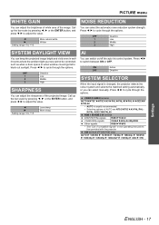
...select manually. ON OFF Active Deactive SYSTEM SELECTOR When the input signal is usually recommended. • Selecting options of the projected image. SDI terminal (PT-DZ6710E only) AUTO H 1080⁄60i H 1035⁄60i H 720⁄60p H 1080⁄24p H 1080⁄50i H 1080⁄30p...the auto iris control system. VIDEO/S-VIDEO terminal AUTO HNTSC HNTSC 4.43 HPAL HPAL-M HPAL-N HSECAM HPAL60 • AUTO is changed, the projector detects the colour system and selects the matched setting automatically, or you can select the automatic noise reduction system strength. OFF 1 2 3...
...select manually. ON OFF Active Deactive SYSTEM SELECTOR When the input signal is usually recommended. • Selecting options of the projected image. SDI terminal (PT-DZ6710E only) AUTO H 1080⁄60i H 1035⁄60i H 720⁄60p H 1080⁄24p H 1080⁄50i H 1080⁄30p...the auto iris control system. VIDEO/S-VIDEO terminal AUTO HNTSC HNTSC 4.43 HPAL HPAL-M HPAL-N HSECAM HPAL60 • AUTO is changed, the projector detects the colour system and selects the matched setting automatically, or you can select the automatic noise reduction system strength. OFF 1 2 3...
Functional Instructions
Page 19
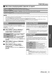
...horizontally, and digital zoom area. Press I H to specially shaped screens, such as moire or noise, you project an image with the projector or by a person who is familiar with an unmatched aspect ratio, the image may distort or some portions may not make successful adjustment.... scale of the creator which is not available. See "SCREEN SETTING" on signals POSITION menu Signals from RGB 1 IN/RGB 2 IN/DVI-D IN and SDI (PT-DZ6710E only) DEFAULT H THROUGH H 16:9 H 4:3 H H-FIT H V-FIT H HV-FIT H DEFAULT Signals from S-VIDEO IN VID AUTO H S1 AUTO H VID AUTO(PRI.) H THROUGH H 16:9...
...horizontally, and digital zoom area. Press I H to specially shaped screens, such as moire or noise, you project an image with the projector or by a person who is familiar with an unmatched aspect ratio, the image may distort or some portions may not make successful adjustment.... scale of the creator which is not available. See "SCREEN SETTING" on signals POSITION menu Signals from RGB 1 IN/RGB 2 IN/DVI-D IN and SDI (PT-DZ6710E only) DEFAULT H THROUGH H 16:9 H 4:3 H H-FIT H V-FIT H HV-FIT H DEFAULT Signals from S-VIDEO IN VID AUTO H S1 AUTO H VID AUTO(PRI.) H THROUGH H 16:9...
Functional Instructions
Page 21
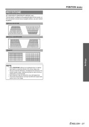
KEYSTONE (PT-DZ6700E/PT-DW6300E/PT-D6000E only) If the projector is recommended. • Some distortion may be projected outside of the image. VERTICAL KEYSTONE VERTICAL SUB KEYSTONE LINEARITY NOTE: • When KEYSTONE setting is set, ... correction will affect the aspect ratio and the size of the actual image area. • You can correct keystone. For a better quality image, installing the projector with a minimum of distortion is aligned non-perpendicularly to the screen, or if the projection screen has an angled surface, you can correct the distortion...
KEYSTONE (PT-DZ6700E/PT-DW6300E/PT-D6000E only) If the projector is recommended. • Some distortion may be projected outside of the image. VERTICAL KEYSTONE VERTICAL SUB KEYSTONE LINEARITY NOTE: • When KEYSTONE setting is set, ... correction will affect the aspect ratio and the size of the actual image area. • You can correct keystone. For a better quality image, installing the projector with a minimum of distortion is aligned non-perpendicularly to the screen, or if the projection screen has an angled surface, you can correct the distortion...
Functional Instructions
Page 23
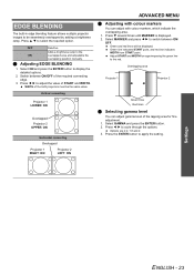
... - 23 Select ON and press the ENTER button to apply the setting. Vertical connecting Projector 1 LOWER: ON Overlapped Projector 2 UPPER: ON Horizontal connecting Overlapped Projector 1 RIGHT: ON Projector 2 LEFT: ON ADVANCED MENU Q Adjusting with colour markers You can adjust gamma level ...cycle through the options. Switch between ON/ OFF. Press I H to switch between ON/OFF of START and WIDTH. Overlapping area Projector 1 Projector 2 Green lines Red lines Q Selecting gamma level You can adjust with colour markers, which indicate the overlapping area. 1. EDGE BLENDING ...
... - 23 Select ON and press the ENTER button to apply the setting. Vertical connecting Projector 1 LOWER: ON Overlapped Projector 2 UPPER: ON Horizontal connecting Overlapped Projector 1 RIGHT: ON Projector 2 LEFT: ON ADVANCED MENU Q Adjusting with colour markers You can adjust gamma level ...cycle through the options. Switch between ON/ OFF. Press I H to switch between ON/OFF of START and WIDTH. Overlapping area Projector 1 Projector 2 Green lines Red lines Q Selecting gamma level You can adjust with colour markers, which indicate the overlapping area. 1. EDGE BLENDING ...
Functional Instructions
Page 25
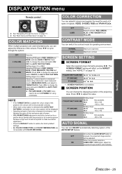
...option is selected while AUTO TEST PATTERN is activated, its one colour pattern will be adjusted. PT-DZ6710E/PT-DZ6700E 16:10*1 H 16:9 H 4:3 PT-DW6300E 16:10*1 H 16:9 PT-D6000E 4:3*1 H 16:9 *1. PT-DZ6710E/PT-DZ6700E PT-DW6300E PT-D6000E Setting range: 16:10 Not available. 16:9 -60 to +60 4:3 -160 ... carried out by a person who is outside the colour range of signals, VIDEO, S-VIDEO, RGB and YPBPR/YCBCR. When the projector detects a COMPUTER or DVI signal, adjust the projected image position automatically. DISPLAY OPTION menu Remote control COLOR CORRECTION You can adjust 6...
...option is selected while AUTO TEST PATTERN is activated, its one colour pattern will be adjusted. PT-DZ6710E/PT-DZ6700E 16:10*1 H 16:9 H 4:3 PT-DW6300E 16:10*1 H 16:9 PT-D6000E 4:3*1 H 16:9 *1. PT-DZ6710E/PT-DZ6700E PT-DW6300E PT-D6000E Setting range: 16:10 Not available. 16:9 -60 to +60 4:3 -160 ... carried out by a person who is outside the colour range of signals, VIDEO, S-VIDEO, RGB and YPBPR/YCBCR. When the projector detects a COMPUTER or DVI signal, adjust the projected image position automatically. DISPLAY OPTION menu Remote control COLOR CORRECTION You can adjust 6...
Functional Instructions
Page 26
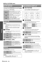
Press I H to none of waning messages. HDMI conversion cable connection SDI IN (PT-DZ6710E only) You can select signal amplitude type. 64-940 4-1019 Normal setting For when grey colour is too close to cycle through the options. 1 ... the current selected input terminal. Refer the instructions of the warning messages will be displayed where the position that is set to OFF, use the projector with utmost care due to select the required option. 1 Yellow 2 Blue 3 White 4 Green 5 Pink 6 Brown J OSD MEMORY The current menu cursor position will be displayed...
Press I H to none of waning messages. HDMI conversion cable connection SDI IN (PT-DZ6710E only) You can select signal amplitude type. 64-940 4-1019 Normal setting For when grey colour is too close to cycle through the options. 1 ... the current selected input terminal. Refer the instructions of the warning messages will be displayed where the position that is set to OFF, use the projector with utmost care due to select the required option. 1 Yellow 2 Blue 3 White 4 Green 5 Pink 6 Brown J OSD MEMORY The current menu cursor position will be displayed...
Functional Instructions
Page 27
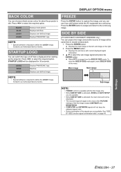
Displays PANASONIC logo. Press I H to select the required option. Deactive Displays user defined image. FREEZE Press the ENTER button to an Authorised Service Centre. SIDE BY SIDE (PT-DZ6710E/PT-DZ6700E/PT-DW6300E only) You can project the image and another source of the menu. Press the ENTER button...page 48. Select OFF to an Authorised Service Centre. Main image Main image NOTE: • Special software is displayed when starting up the projector. Displays solid blue. NOTE: • Special software is idle. STARTUP LOGO will not keep the adjusted aspect ratio. • Some ...
Displays PANASONIC logo. Press I H to select the required option. Deactive Displays user defined image. FREEZE Press the ENTER button to an Authorised Service Centre. SIDE BY SIDE (PT-DZ6710E/PT-DZ6700E/PT-DW6300E only) You can project the image and another source of the menu. Press the ENTER button...page 48. Select OFF to an Authorised Service Centre. Main image Main image NOTE: • Special software is displayed when starting up the projector. Displays solid blue. NOTE: • Special software is idle. STARTUP LOGO will not keep the adjusted aspect ratio. • Some ...
Functional Instructions
Page 28
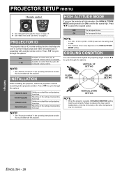
... the projection method according to control from any ID numbered remote control or computer. The fan speed is provided with the projector. Press I H to observe this may result in the operating instructions booklet that helps the user to cycle through the options. ... the same ID numbered remote control. Press I H to control multiple projectors either simultaneously or separately with the projector. VERTICAL UP SETTING FLOOR SETTING CEILING SETTING VERTICAL DOWN SETTING NOTE: • When the projector is angled, COOLING CONDITION setting must be set the fan speed high....
... the projection method according to control from any ID numbered remote control or computer. The fan speed is provided with the projector. Press I H to observe this may result in the operating instructions booklet that helps the user to cycle through the options. ... the same ID numbered remote control. Press I H to control multiple projectors either simultaneously or separately with the projector. VERTICAL UP SETTING FLOOR SETTING CEILING SETTING VERTICAL DOWN SETTING NOTE: • When the projector is angled, COOLING CONDITION setting must be set the fan speed high....
Functional Instructions
Page 29
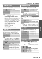
... only one lamp remains off first. The electrical consumption in LAMP SELECT, LAMP RELAY is selected as the LAMP POWER setting) are exceeded, the projector will light. RS-232C This sets the communication parameters at the serial terminals. (IN) BAUDRATE Select 9600, 19200 or 38400. (IN) PARITY... used to automatically switch the lamps that are not available. USER For changing an optional input module or customising the pin assignments. Settings PROJECTOR SETUP menu LAMP SELECT You can occur as a result of continuous use. However, if both lamps light for the set to 23:...
... only one lamp remains off first. The electrical consumption in LAMP SELECT, LAMP RELAY is selected as the LAMP POWER setting) are exceeded, the projector will light. RS-232C This sets the communication parameters at the serial terminals. (IN) BAUDRATE Select 9600, 19200 or 38400. (IN) PARITY... used to automatically switch the lamps that are not available. USER For changing an optional input module or customising the pin assignments. Settings PROJECTOR SETUP menu LAMP SELECT You can occur as a result of continuous use. However, if both lamps light for the set to 23:...
Functional Instructions
Page 30
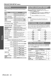
...shortcut. FG 40 MIN. FG FUNCTION BUTTON You can assign a certain menu function to 90 minutes at intervals of the projector about the following items. Items Description INPUT Displays the input selection state. INTAKE AIR TEMP. QUANTITY Displays the filter remaining quantity...by pressing I H to "0". 1. Press I , then press the ENTER button. 3. SYSTEM DAYLIGHT Switches the SYSTEM VIEW DAYLIGHT VIEW setting. PROJECTOR SETUP menu STATUS You can set the timer to "0". FG 60 MIN. FREEZE Freezes the image. AROUND LAMP TEMP. NAME Displays the input...
...shortcut. FG 40 MIN. FG FUNCTION BUTTON You can assign a certain menu function to 90 minutes at intervals of the projector about the following items. Items Description INPUT Displays the input selection state. INTAKE AIR TEMP. QUANTITY Displays the filter remaining quantity...by pressing I H to "0". 1. Press I , then press the ENTER button. 3. SYSTEM DAYLIGHT Switches the SYSTEM VIEW DAYLIGHT VIEW setting. PROJECTOR SETUP menu STATUS You can set the timer to "0". FG 60 MIN. FREEZE Freezes the image. AROUND LAMP TEMP. NAME Displays the input...
Functional Instructions
Page 31
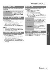
... the current located time zone. Adjust YEAR, MONTH, DAY, HOUR and MINUTE by ALL USER DATA, switch off the power and restart the projector. Perform the SECURITY PASSWORD. Press I to initialise. 2. The SECURITY PASSWORD will be asked to perform. 2. Press I to reflect the saved...factory settings. See "SECURITY PASSWORD" on page 35. 3. See "SECURITY PASSWORD" on page 35. 4. NOTE: • E-mail settings of the projector. 1. Press I H, then select APPLY and press the ENTER button. ALL USER DATA ENTRY SIGNAL NETWORK/E-MAIL LOGO IMAGE All setting values including registered signals...
... the current located time zone. Adjust YEAR, MONTH, DAY, HOUR and MINUTE by ALL USER DATA, switch off the power and restart the projector. Perform the SECURITY PASSWORD. Press I to initialise. 2. The SECURITY PASSWORD will be asked to perform. 2. Press I to reflect the saved...factory settings. See "SECURITY PASSWORD" on page 35. 3. See "SECURITY PASSWORD" on page 35. 4. NOTE: • E-mail settings of the projector. 1. Press I H, then select APPLY and press the ENTER button. ALL USER DATA ENTRY SIGNAL NETWORK/E-MAIL LOGO IMAGE All setting values including registered signals...
Functional Instructions
Page 33
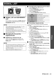
... "Main menu and Sub-menu" on page 15. Displays the REGISTERED SIGNAL STATUS. Displays REGISTERED SIGNAL LIST and confirm the data is applied to the projector, press the MENU button to register to the list. Displays the character list. 4. Select OK and press the ENTER button. SIGNAL LIST Remote control See...
... "Main menu and Sub-menu" on page 15. Displays the REGISTERED SIGNAL STATUS. Displays REGISTERED SIGNAL LIST and confirm the data is applied to the projector, press the MENU button to register to the list. Displays the character list. 4. Select OK and press the ENTER button. SIGNAL LIST Remote control See...


