Functional Instructions
Page 2
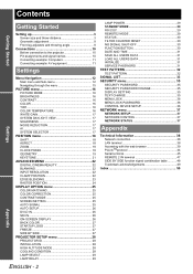
... - 2 LAMP POWER 29 STANDBY MODE 29 RS-232C 29 REMOTE2 MODE 29 STATUS 30 FILTER COUNTER RESET 30 NO SIGNAL SHUT-OFF 30 FUNCTION BUTTON 30 DATE AND TIME 31 SAVE ALL USERS DATA 31 LOAD ALL USERS DATA 31 INITIALIZE 31 SERVICE PASSWORD 31 TEST PATTERN 32 TEST PATTERN 32 SIGNAL LIST 33 SECURITY menu 35 SECURITY PASSWORD 35 SECURITY PASSWORD CHANGE 35 DISPLAY SETTING 35 TEXT CHANGE 35 MENU LOCK 36 MENU LOCK PASSWORD 36 CONTROL DEVICE SETUP 36 NETWORK menu 37 NETWORK SETUP 37 NETWORK CONTROL 37 NETWORK STATUS...
... - 2 LAMP POWER 29 STANDBY MODE 29 RS-232C 29 REMOTE2 MODE 29 STATUS 30 FILTER COUNTER RESET 30 NO SIGNAL SHUT-OFF 30 FUNCTION BUTTON 30 DATE AND TIME 31 SAVE ALL USERS DATA 31 LOAD ALL USERS DATA 31 INITIALIZE 31 SERVICE PASSWORD 31 TEST PATTERN 32 TEST PATTERN 32 SIGNAL LIST 33 SECURITY menu 35 SECURITY PASSWORD 35 SECURITY PASSWORD CHANGE 35 DISPLAY SETTING 35 TEXT CHANGE 35 MENU LOCK 36 MENU LOCK PASSWORD 36 CONTROL DEVICE SETUP 36 NETWORK menu 37 NETWORK SETUP 37 NETWORK CONTROL 37 NETWORK STATUS...
Functional Instructions
Page 3
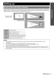
... calculation results are used when DLP projectors are approximate and may differ slightly from the actual measurements. • The throw ratio is based on the value during projection onto an 80-inch screen size. • Lens shift is not available when using the ET-DLE055, and so the height position (H) is SH/2. • See the operating instructions that is a loss...
... calculation results are used when DLP projectors are approximate and may differ slightly from the actual measurements. • The throw ratio is based on the value during projection onto an 80-inch screen size. • Lens shift is not available when using the ET-DLE055, and so the height position (H) is SH/2. • See the operating instructions that is a loss...
Functional Instructions
Page 13
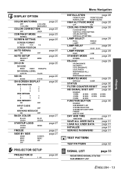
... ENGLISH - 13 Settings DISPLAY OPTION COLOR MATCHING OFF 3 COLORS 7 COLORS MEASURED COLOR CORRECTION OFF USER CONTRAST MODE NORMAL HIGH SCREEN SETTING SCREEN FORMAT 16:10 16:9 4:3 SCREEN POSITION AUTO SIGNAL ON AUTO SETUP DEFAULT USER DVI-D IN OFF WIDE DVI EDID EDID3 EDID1 EDID2(PC) DVI SIGNAL LEVEL 0-255:PC 16-235 SDI IN 64-940 4-1019 ON-SCREEN DISPLAY OSD POSITION 1 2 3 4 5 6 7 8 9 OSD DESIGN 1 2 3 4 5 6 OSD MEMORY ON OFF INPUT GUIDE ON OFF WARNING MESSAGE ON OFF...
... ENGLISH - 13 Settings DISPLAY OPTION COLOR MATCHING OFF 3 COLORS 7 COLORS MEASURED COLOR CORRECTION OFF USER CONTRAST MODE NORMAL HIGH SCREEN SETTING SCREEN FORMAT 16:10 16:9 4:3 SCREEN POSITION AUTO SIGNAL ON AUTO SETUP DEFAULT USER DVI-D IN OFF WIDE DVI EDID EDID3 EDID1 EDID2(PC) DVI SIGNAL LEVEL 0-255:PC 16-235 SDI IN 64-940 4-1019 ON-SCREEN DISPLAY OSD POSITION 1 2 3 4 5 6 7 8 9 OSD DESIGN 1 2 3 4 5 6 OSD MEMORY ON OFF INPUT GUIDE ON OFF WARNING MESSAGE ON OFF...
Functional Instructions
Page 16
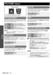
... More greenish COLOR TEMPERATURE You can adjust the contrast of the projected image. I , H or the ENTER button to 63 (Default: 32) NOTE: • With excessive unbalanced adjustment, such as extremely high with signal image. Select the required option and press I H Setting range: -31 to the default setting. • Adjust COLOR TEMPERATURE with extremely low setting, all the colours may be displayed abnormally. Setting range WHITE BALANCE HIGH: 0 to 255 (Default: 255) WHITE BALANCE LOW...
... More greenish COLOR TEMPERATURE You can adjust the contrast of the projected image. I , H or the ENTER button to 63 (Default: 32) NOTE: • With excessive unbalanced adjustment, such as extremely high with signal image. Select the required option and press I H Setting range: -31 to the default setting. • Adjust COLOR TEMPERATURE with extremely low setting, all the colours may be displayed abnormally. Setting range WHITE BALANCE HIGH: 0 to 255 (Default: 255) WHITE BALANCE LOW...
Functional Instructions
Page 17
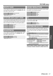
... of the projected image. ON OFF Active Deactive SYSTEM SELECTOR When the input signal is usually recommended. • Selecting options of the image. Press I H Setting range: 0 to adjust the value. OFF 1 2 3 Deactive Low Middle High SHARPNESS You can adjust the sharpness of compatible signals" in welllit rooms where the ambient light sources cannot be controlled, such as when a door opens or when window coverings fail to...
... of the projected image. ON OFF Active Deactive SYSTEM SELECTOR When the input signal is usually recommended. • Selecting options of the image. Press I H Setting range: 0 to adjust the value. OFF 1 2 3 Deactive Low Middle High SHARPNESS You can adjust the sharpness of compatible signals" in welllit rooms where the ambient light sources cannot be controlled, such as when a door opens or when window coverings fail to...

Functional Instructions
Page 18
... be cropped. Effective with the resolution of SCREEN SETTING in input signal, and automatically switch the aspect ratio between 4:3 and 16:9. Q THROUGH The image will not be displayed with S-VIDEO signals. Vertical adjustment F Moves up the image. Q VID AUTO Signals which contain video ID or S1 signal in DISPLAY OPTION menu. Q V-FIT The 16:9 (16:10)/15:9 image will be displayed in advance, and then change the aspect ratio according to...
... be cropped. Effective with the resolution of SCREEN SETTING in input signal, and automatically switch the aspect ratio between 4:3 and 16:9. Q THROUGH The image will not be displayed with S-VIDEO signals. Vertical adjustment F Moves up the image. Q VID AUTO Signals which contain video ID or S1 signal in DISPLAY OPTION menu. Q V-FIT The 16:9 (16:10)/15:9 image will be displayed in advance, and then change the aspect ratio according to...
Functional Instructions
Page 19
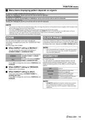
... H HV-FIT H DEFAULT Signals from S-VIDEO IN VID AUTO H S1 AUTO H VID AUTO(PRI.) H THROUGH H 16:9 H 4:3 H H-FIT H V-FIT H HV-FIT H VID AUTO Signals from other terminals VID AUTO H THROUGH H 16:9 H 4:3 H H-FIT H V-FIT H HV-FIT H VID AUTO NOTE: • If you can fine adjust the timing of the clock. (Signals from a connected computer. ZOOM You can control the digital zoom scale vertically and horizontally, and digital zoom area. See "SCREEN SETTING" on the...
... H HV-FIT H DEFAULT Signals from S-VIDEO IN VID AUTO H S1 AUTO H VID AUTO(PRI.) H THROUGH H 16:9 H 4:3 H H-FIT H V-FIT H HV-FIT H VID AUTO Signals from other terminals VID AUTO H THROUGH H 16:9 H 4:3 H H-FIT H V-FIT H HV-FIT H VID AUTO NOTE: • If you can fine adjust the timing of the clock. (Signals from a connected computer. ZOOM You can control the digital zoom scale vertically and horizontally, and digital zoom area. See "SCREEN SETTING" on the...

Functional Instructions
Page 22
... 12. Press I H to the selected input signal. See "Main menu and Sub-menu" on the screen. Setting range: 0 to change the setting properly. UPPER LOWER Q Setting range Models PT-DZ6710E/PT-DZ6700E PT-DW6300E PT-D6000E Vertical 0 - 599 0 - 399 0 - 383 Horizontal 0 - 959 0 - 639 0 - 511 INPUT RESOLUTION Input resolution adjustment achieves the best image when the screen flickers or halo is not 2:2 pulldown may be distorted during image projection using a VCR and so on. LEFT RIGHT...
... 12. Press I H to the selected input signal. See "Main menu and Sub-menu" on the screen. Setting range: 0 to change the setting properly. UPPER LOWER Q Setting range Models PT-DZ6710E/PT-DZ6700E PT-DW6300E PT-D6000E Vertical 0 - 599 0 - 399 0 - 383 Horizontal 0 - 959 0 - 639 0 - 511 INPUT RESOLUTION Input resolution adjustment achieves the best image when the screen flickers or halo is not 2:2 pulldown may be distorted during image projection using a VCR and so on. LEFT RIGHT...
Functional Instructions
Page 25
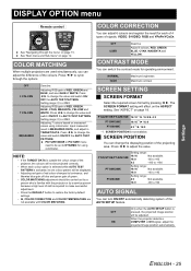
... restore the factory default settings. • AI, COLOR CORRECTION and COLOR TEMPERATURE are used simultaneously, you can adjust the difference of skill is activated, its one colour pattern will be adjusted. PICTURE MODE in TARGET DATA. J SCREEN POSITION You can change the value and switch ON/OFF the AUTO TEST PATTERN. When the projector detects a COMPUTER or DVI signal, adjust the projected image position automatically. DISPLAY OPTION menu Remote control COLOR CORRECTION You can adjust 6 colours and...
... restore the factory default settings. • AI, COLOR CORRECTION and COLOR TEMPERATURE are used simultaneously, you can adjust the difference of skill is activated, its one colour pattern will be adjusted. PICTURE MODE in TARGET DATA. J SCREEN POSITION You can change the value and switch ON/OFF the AUTO TEST PATTERN. When the projector detects a COMPUTER or DVI signal, adjust the projected image position automatically. DISPLAY OPTION menu Remote control COLOR CORRECTION You can adjust 6 colours and...
Functional Instructions
Page 26
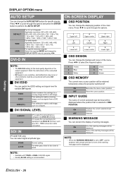
... can change the AUTO SETUP feature for the best quality depends on the output equipment. Refer the instructions of the menu. Press I H to select the required option. 1 Yellow 2 Blue 3 White 4 Green 5 Pink 6 Brown J OSD MEMORY The current menu cursor position will be displayed. NOTE: • When the WARNING MESSAGE is set to AV equipment via DVI-D IN terminal (TV scale) For connecting to OFF, use the projector...
... can change the AUTO SETUP feature for the best quality depends on the output equipment. Refer the instructions of the menu. Press I H to select the required option. 1 Yellow 2 Blue 3 White 4 Green 5 Pink 6 Brown J OSD MEMORY The current menu cursor position will be displayed. NOTE: • When the WARNING MESSAGE is set to AV equipment via DVI-D IN terminal (TV scale) For connecting to OFF, use the projector...
Functional Instructions
Page 27
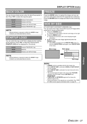
... of the PICTURE settings of the first image except CONTRAST and BRIGHTNESS. • COMPUTER and NETWORK signals will apply to an Authorised Service Centre. NOTE: • Special software is required to select the required option. Press the MENU button. STARTUP LOGO You can project the image and another source of the menu. STARTUP LOGO will be displayed. • The second image will not keep the adjusted aspect...
... of the PICTURE settings of the first image except CONTRAST and BRIGHTNESS. • COMPUTER and NETWORK signals will apply to an Authorised Service Centre. NOTE: • Special software is required to select the required option. Press the MENU button. STARTUP LOGO You can project the image and another source of the menu. STARTUP LOGO will be displayed. • The second image will not keep the adjusted aspect...
Functional Instructions
Page 29
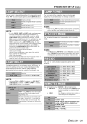
... the projector, projection will light. RESPONSE(ID ALL) Select ON or OFF. DEFAULT The pin assignment of the REMOTE 2 IN terminal is used for short periods of time, the lamps will need to be replaced more frequently. Settings PROJECTOR SETUP menu LAMP SELECT You can select a lamp lighting pattern for using the projector for a continuous period of 24 hours or more, this setting can be used to automatically switch the lamps that are turned...
... the projector, projection will light. RESPONSE(ID ALL) Select ON or OFF. DEFAULT The pin assignment of the REMOTE 2 IN terminal is used for short periods of time, the lamps will need to be replaced more frequently. Settings PROJECTOR SETUP menu LAMP SELECT You can select a lamp lighting pattern for using the projector for a continuous period of 24 hours or more, this setting can be used to automatically switch the lamps that are turned...
Functional Instructions
Page 30
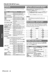
... BY SIDE Start the SIDE BY SIDE mode. NAME Displays the input signal name. OPTICS MODULE TEMP. NOTE: • See "Replacing the Auto Cleaning Filter (ACF)" in the operating instructions booklet that is detected. NO SIGNAL SHUT-OFF You can set the timer to 90 minutes at intervals of STATUS will be reset to "0". Press I H to select the required period from 10 to switch off the power of the projector after...
... BY SIDE Start the SIDE BY SIDE mode. NAME Displays the input signal name. OPTICS MODULE TEMP. NOTE: • See "Replacing the Auto Cleaning Filter (ACF)" in the operating instructions booklet that is detected. NO SIGNAL SHUT-OFF You can set the timer to 90 minutes at intervals of STATUS will be reset to "0". Press I H to select the required period from 10 to switch off the power of the projector after...
Functional Instructions
Page 33
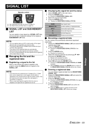
... the input signals and memory numbers. • If a menu is displayed, the signal will be registered at the instant they are used, the data of the registered data are numbered over 12 pages (A to the REGISTERED SIGNAL LIST without any change . Press the DEFAULT button. Displays REGISTERED SIGNAL LIST and confirm the data is applied to the projector, press the MENU button to register to the list When a new format input signal is...
... the input signals and memory numbers. • If a menu is displayed, the signal will be registered at the instant they are used, the data of the registered data are numbered over 12 pages (A to the REGISTERED SIGNAL LIST without any change . Press the DEFAULT button. Displays REGISTERED SIGNAL LIST and confirm the data is applied to the projector, press the MENU button to register to the list When a new format input signal is...

Functional Instructions
Page 34
... MENU button. You can return to L: 8 data items can restore the sub memory data when using signals from the screen after adjustment. indicates as BRIGHTNESS, CONTRAST or ASPECT. Displays the SUB MEMORY LIST. 2. If all the memories are numbered over 12 pages (A to the previous step by pressing the MENU button. 3. Location address Sub memory number: NOTE: • The memories are used, the data of the signal will be displayed...
... MENU button. You can return to L: 8 data items can restore the sub memory data when using signals from the screen after adjustment. indicates as BRIGHTNESS, CONTRAST or ASPECT. Displays the SUB MEMORY LIST. 2. If all the memories are numbered over 12 pages (A to the previous step by pressing the MENU button. 3. Location address Sub memory number: NOTE: • The memories are used, the data of the signal will be displayed...
Functional Instructions
Page 37
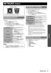
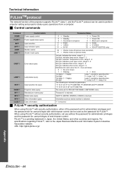
... screen will be displayed. ON: When using a DHCP server. Select OK and press the ENTER button. The random numbers are 8-byte values sent from a computer with the PJLinkTM protocol. Press the ENTER button. 3. WEB CONTROL PJLink CONTROL COMMAND CONTROL*1 COMMAND PORT STORE For when controlling from the projector when connecting. NETWORK SETUP Make the initial network settings before using the network connection. 1. Select the required item to change . 2. Enter correct IP ADDRESS numbers. NETWORK STATUS You can switch...
... screen will be displayed. ON: When using a DHCP server. Select OK and press the ENTER button. The random numbers are 8-byte values sent from a computer with the PJLinkTM protocol. Press the ENTER button. 3. WEB CONTROL PJLink CONTROL COMMAND CONTROL*1 COMMAND PORT STORE For when controlling from the projector when connecting. NETWORK SETUP Make the initial network settings before using the network connection. 1. Select the required item to change . 2. Enter correct IP ADDRESS numbers. NETWORK STATUS You can switch...

Functional Instructions
Page 41
... Items Input IP address Description Enter the required IP address, such as E-mail server, POP server or DNS server, then click Submit to check whether the connection is selected in the menu) See "FUNCTION BUTTON" on the top. See the operation instruction booklet that is provided with the projector. Items Time Zone Date Time Description Select the located time zone, then click Set time zone. Enter...
... Items Input IP address Description Enter the required IP address, such as E-mail server, POP server or DNS server, then click Submit to check whether the connection is selected in the menu) See "FUNCTION BUTTON" on the top. See the operation instruction booklet that is provided with the projector. Items Time Zone Date Time Description Select the located time zone, then click Set time zone. Enter...

Functional Instructions
Page 43
... your dealer. COVER OPEN The lamp unit cover is getting less. FILTER REMAIN The filter remaining is not attached securely. Displays the lamp lit hours. Consult your dealer OPTICS MODULE TEMP.SENSOR Trouble has occurred in the colour wheel or colour wheel or its drive circuit. Error information When Error (Detail) is high. J STATUS Q Projector status Click the Projector status tab on the power. Displays the firmware version of the projector. Displays the input switching status. Displays self diagnosis information...
... your dealer. COVER OPEN The lamp unit cover is getting less. FILTER REMAIN The filter remaining is not attached securely. Displays the lamp lit hours. Consult your dealer OPTICS MODULE TEMP.SENSOR Trouble has occurred in the colour wheel or colour wheel or its drive circuit. Error information When Error (Detail) is high. J STATUS Q Projector status Click the Projector status tab on the power. Displays the firmware version of the projector. Displays the input switching status. Displays self diagnosis information...
Functional Instructions
Page 44
... time 2nd digit: 0 = Lamp 1 off, 1 = Lamp 1 on 3rd digits (1 - 5 digits): Lamp 2 cumulative operating time 4th digit: 0 = Lamp 2 off, 1 = Lamp 2 on The following are returned as version number is a pending trademark in progress 12 = RGB2 22 = S-VIDEO 32 = SDI (PT-DZ6710E only) 30 = Shutter mode off (picture mute cancelled) 31 = Shutter mode on (picture mute) 1st byte: Indicates fan errors, range 0 - 2. 2nd byte: Indicates lamp errors, range 0 - 2. 3rd byte: Indicates Temperature errors, range 0 - 2. 4th byte: Indicates cover open errors, range 0 - 2. 5th byte: Indicates filter...
... time 2nd digit: 0 = Lamp 1 off, 1 = Lamp 1 on 3rd digits (1 - 5 digits): Lamp 2 cumulative operating time 4th digit: 0 = Lamp 2 off, 1 = Lamp 2 on The following are returned as version number is a pending trademark in progress 12 = RGB2 22 = S-VIDEO 32 = SDI (PT-DZ6710E only) 30 = Shutter mode off (picture mute cancelled) 31 = Shutter mode on (picture mute) 1st byte: Indicates fan errors, range 0 - 2. 2nd byte: Indicates lamp errors, range 0 - 2. 3rd byte: Indicates Temperature errors, range 0 - 2. 4th byte: Indicates cover open errors, range 0 - 2. 5th byte: Indicates filter...
Functional Instructions
Page 50
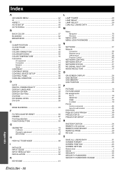
... 23 F FILTER COUNTER RESET 30 FREEZE 27 Front leg adjusters 9 FUNCTION BUTTON 30 G GEOMETRY 19 CURVED 20 Geometric adjustment 8 KEYSTONE 20 H HIGH ALTITUDE MODE 28 I INITIALIZE 31 INPUT GUIDE 26 INPUT RESOLUTION 22 INSTALLATION 28 K KEYSTONE 21 L LAMP POWER 29 LAMP RELAY 29 LAMP SELECT 29 LOAD ALL USERS DATA 31 M Menu Navigation 15 Structure 12 MENU LOCK 36 MENU LOCK PASSWORD 36 N NETWORK 37 Network Connection 38 Detailed set up 41 LAN terminal 38 Projector Control 40 NETWORK CONTROL 37 NETWORK SETUP 37 NETWORK STATUS 37 NO SIGNAL SHUT-OFF 30...
... 23 F FILTER COUNTER RESET 30 FREEZE 27 Front leg adjusters 9 FUNCTION BUTTON 30 G GEOMETRY 19 CURVED 20 Geometric adjustment 8 KEYSTONE 20 H HIGH ALTITUDE MODE 28 I INITIALIZE 31 INPUT GUIDE 26 INPUT RESOLUTION 22 INSTALLATION 28 K KEYSTONE 21 L LAMP POWER 29 LAMP RELAY 29 LAMP SELECT 29 LOAD ALL USERS DATA 31 M Menu Navigation 15 Structure 12 MENU LOCK 36 MENU LOCK PASSWORD 36 N NETWORK 37 Network Connection 38 Detailed set up 41 LAN terminal 38 Projector Control 40 NETWORK CONTROL 37 NETWORK SETUP 37 NETWORK STATUS 37 NO SIGNAL SHUT-OFF 30...


