
English Manual
Page 2
... accuracy of ICON Health & Fitness, Inc. 2 NordicTrack is not a medical device. Read all instructions in -home use the exercise cycle in general. 11. Keep the exercise cycle away from the exercise cycle at all parts regularly. Keep children under the exercise cycle to ensure that could become caught on a level surface. tions before using the exercise cycle; The pulse sensor is a registered trademark of heart rate readings. ICON assumes...
... accuracy of ICON Health & Fitness, Inc. 2 NordicTrack is not a medical device. Read all instructions in -home use the exercise cycle in general. 11. Keep the exercise cycle away from the exercise cycle at all parts regularly. Keep children under the exercise cycle to ensure that could become caught on a level surface. tions before using the exercise cycle; The pulse sensor is a registered trademark of heart rate readings. ICON assumes...
English Manual
Page 3
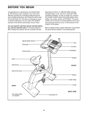
...-free at 1-888-825-2588, Monday through Friday, 6 a.m. The NordicTrack® SL 705 offers an impressive array of features designed to the exercise cycle (see the front cover of the decal). For your home. The serial number can be found on a decal attached to let you use the exercise cycle. until 6 p.m. The model number is included Leveling Foot Fan Console Handlebar Upright FRONT Wheel Pedal Strap Pedal...
...-free at 1-888-825-2588, Monday through Friday, 6 a.m. The NordicTrack® SL 705 offers an impressive array of features designed to the exercise cycle (see the front cover of the decal). For your home. The serial number can be found on a decal attached to let you use the exercise cycle. until 6 p.m. The model number is included Leveling Foot Fan Console Handlebar Upright FRONT Wheel Pedal Strap Pedal...

English Manual
Page 5
... Wire Harness. While another person lifts the rear of the Frame (1), attach the Rear Stabilizer (16) to the Frame with four M8 x 40mm Button Screws (54) and four M8 Split Washers (55). 2 1 16 3. Make sure that the curved sides of the Upper Wire ...Upright (2). Do not pinch the Upper Wire Harness (42) during this step. 59 55 Hole 3 42 2 5 Attach the Handlebar to the Lower Wire Harness (43). Be careful to avoid pinching the Wire Harnesses (42, 43). Slide the Upright onto the Frame (1). Make sure that the Upright (2) is turned so the top slopes down in the direction...
... Wire Harness. While another person lifts the rear of the Frame (1), attach the Rear Stabilizer (16) to the Frame with four M8 x 40mm Button Screws (54) and four M8 Split Washers (55). 2 1 16 3. Make sure that the curved sides of the Upper Wire ...Upright (2). Do not pinch the Upper Wire Harness (42) during this step. 59 55 Hole 3 42 2 5 Attach the Handlebar to the Lower Wire Harness (43). Be careful to avoid pinching the Wire Harnesses (42, 43). Slide the Upright onto the Frame (1). Make sure that the Upright (2) is turned so the top slopes down in the direction...

English Manual
Page 6
... this step. Carefully insert all excess wires into one of the holes in the side of the Seat. Move the Seat to avoid pinching the wires. 6. Next, locate the pulse wire extending from the Handlebar and connect it . Then, turn the Knob clockwise until the pin on the Console. Attach the Seat Bracket (7) to the Seat Carriage (11) with two M8 x 25mm Patch Screws (59). Ground 5 42 Wires 57 Pulse Wire...
... this step. Carefully insert all excess wires into one of the holes in the side of the Seat. Move the Seat to avoid pinching the wires. 6. Next, locate the pulse wire extending from the Handlebar and connect it . Then, turn the Knob clockwise until the pin on the Console. Attach the Seat Bracket (7) to the Seat Carriage (11) with two M8 x 25mm Patch Screws (59). Ground 5 42 Wires 57 Pulse Wire...
English Manual
Page 7
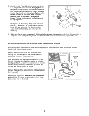
... steps below to use the exercise cycle. Attach the Left Pedal Strap to the Left Pedal (22), and adjust it to protect the floor. Reattach the access door. Access Door 4 Pin Wire Receiver Screws 7 Using an adjustable wrench, firmly tighten the Left Pedal counterclockwise into the Right Crank Arm. Make sure that the receiver is marked with the chest pulse sensor. make sure that all parts are pinched. You may need to install...
... steps below to use the exercise cycle. Attach the Left Pedal Strap to the Left Pedal (22), and adjust it to protect the floor. Reattach the access door. Access Door 4 Pin Wire Receiver Screws 7 Using an adjustable wrench, firmly tighten the Left Pedal counterclockwise into the Right Crank Arm. Make sure that the receiver is marked with the chest pulse sensor. make sure that all parts are pinched. You may need to install...
English Manual
Page 9
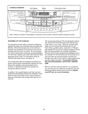
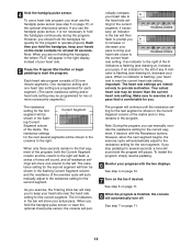
... trainer in your workout. Using the included audio cable, you through an effective workout. High-energy music provides added motivation. Explore www.iFIT.com for more enjoyable and effective. Note: For information about an optional chest pulse sensor, see page 19. In addition, the console features two heart rate programs that automatically change the resistance of a button. The console also offers six resistance and pace programs. Each program automatically changes the resistance of the exercise...
... trainer in your workout. Using the included audio cable, you through an effective workout. High-energy music provides added motivation. Explore www.iFIT.com for more enjoyable and effective. Note: For information about an optional chest pulse sensor, see page 19. In addition, the console features two heart rate programs that automatically change the resistance of a button. The console also offers six resistance and pace programs. Each program automatically changes the resistance of the exercise...
English Manual
Page 10
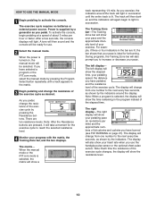
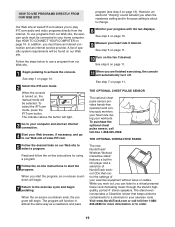
... Program Select button repeatedly until the entire track is ideal for use the handgrip pulse sensor or the optional chest pulse sensor. The track will then darken and the indicators will show the resistance level. 10 The Training Zone bar-The Training Zone bar will again begin pedaling at a speed of about 3 miles per mile) and the approximate numbers of the exercise cycle changes, the display will show the elapsed time, your pedaling speed, the distance...
... Program Select button repeatedly until the entire track is ideal for use the handgrip pulse sensor or the optional chest pulse sensor. The track will then darken and the indicators will show the resistance level. 10 The Training Zone bar-The Training Zone bar will again begin pedaling at a speed of about 3 miles per mile) and the approximate numbers of the exercise cycle changes, the display will show the elapsed time, your pedaling speed, the distance...
English Manual
Page 11
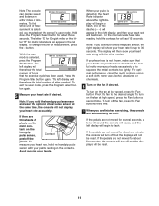
... pulse sensor and wear the optional chest pulse sensor at least 15 seconds. Note: If you must select the console's user mode. If the pedals are not moved for up to flash. If the pedals are not moved for about three seconds. While the user mode is selected, press the Program Start button. When your heart rate will begin to flash, one minute, the console will turn off, but the displays will be reset...
... pulse sensor and wear the optional chest pulse sensor at least 15 seconds. Note: If you must select the console's user mode. If the pedals are not moved for up to flash. If the pedals are not moved for about three seconds. While the user mode is selected, press the Program Start button. When your heart rate will begin to flash, one minute, the console will turn off, but the displays will be reset...
English Manual
Page 12
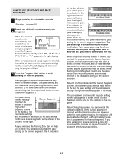
... program will last. 3 Press the Program Start button or begin pedaling to the resistance setting for the program. To restart the program, simply resume pedaling. 12 When a resistance and pace program is flashing, your pace. ing Current Segment column of different lengths. Current Segment ment will be shown in the bar will be selected. Make sure to the left display will show how long the program...
... program will last. 3 Press the Program Start button or begin pedaling to the resistance setting for the program. To restart the program, simply resume pedaling. 12 When a resistance and pace program is flashing, your pace. ing Current Segment column of different lengths. Current Segment ment will be shown in the bar will be selected. Make sure to the left display will show how long the program...
English Manual
Page 13
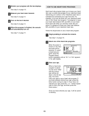
... 220. Once you to use a heart rate program. 1 Begin pedaling to keep your heart rate between 50% and 80% of your maximum heart rate during your workout. (Your maximum heart rate is estimated by subtracting your age, it will be saved in memory. 13 4 Monitor your age. See step 7 on , the manual mode will be selected. Follow the steps below to use a heart rate program. If you exercise; For example, if you...
... 220. Once you to use a heart rate program. 1 Begin pedaling to keep your heart rate between 50% and 80% of your maximum heart rate during your workout. (Your maximum heart rate is estimated by subtracting your age, it will be saved in memory. 13 4 Monitor your age. See step 7 on , the manual mode will be selected. Follow the steps below to use a heart rate program. If you exercise; For example, if you...
English Manual
Page 14
... resistance settings will peri- To restart the program, simply resume pedaling. 6 Monitor your heart rate near the current heart rate setting. The resistance setting for the second segment will help you should hold the handgrip pulse sensor or wear the optional chest pulse sensor, the console will move one heart rate setting are intend- Make sure to the right will flash, a series of the program, both the Current Segment column and the column to exercise...
... resistance settings will peri- To restart the program, simply resume pedaling. 6 Monitor your heart rate near the current heart rate setting. The resistance setting for the second segment will help you should hold the handgrip pulse sensor or wear the optional chest pulse sensor, the console will move one heart rate setting are intend- Make sure to the right will flash, a series of the program, both the Current Segment column and the column to exercise...
English Manual
Page 15
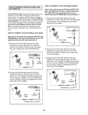
... OUT and PHONES jacks, see instruction A below . To use iFIT.com programs directly from our Web site, the exercise cycle must be connected to your portable CD player, portable stereo, home stereo, or computer with CD player. Plug one end of the Y-adapter. A PHONES LINE OUT LINE OUT PHONES Audio Cable Headphones B. Plug the other end of the cable into a 1/8" Y-adapter (available at electronics stores...
... OUT and PHONES jacks, see instruction A below . To use iFIT.com programs directly from our Web site, the exercise cycle must be connected to your portable CD player, portable stereo, home stereo, or computer with CD player. Plug one end of the Y-adapter. A PHONES LINE OUT LINE OUT PHONES Audio Cable Headphones B. Plug the other end of the cable into a 1/8" Y-adapter (available at electronics stores...
English Manual
Page 16
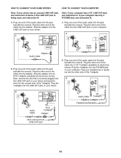
... CONNECT YOUR HOME STEREO HOW TO CONNECT YOUR COMPUTER Note: If your computer. Plug the adapter into the jack beneath the console. Plug one end of the cable into the jack beneath the console. A. Plug the other side of the audio cable into an RCA Y-adapter (available at electronics stores). Plug one end of the Y-adapter. B PHONES B CD VCR Amp LINE OUT Audio Cable RCA Y-adapter Adapter Audio Cable 1/8" Y-adapter Headphones/Speakers Wire removed...
... CONNECT YOUR HOME STEREO HOW TO CONNECT YOUR COMPUTER Note: If your computer. Plug the adapter into the jack beneath the console. Plug one end of the cable into the jack beneath the console. A. Plug the other side of the audio cable into an RCA Y-adapter (available at electronics stores). Plug one end of the Y-adapter. B PHONES B CD VCR Amp LINE OUT Audio Cable RCA Y-adapter Adapter Audio Cable 1/8" Y-adapter Headphones/Speakers Wire removed...

English Manual
Page 17
..., see instruction A below. Plug one end of the cable into the jack beneath the console. Next, remove the wire that is being used, see HOW TO CONNECT YOUR HOME STEREO on your VCR and plug the wire into the unused side of the audio cable into the adapter. IN VIDEO AUDIO IN CH 34 OUT RF OUT AUDIO OUT jack on page 16. A ANT. IN VIDEO AUDIO IN CH...
..., see instruction A below. Plug one end of the cable into the jack beneath the console. Next, remove the wire that is being used, see HOW TO CONNECT YOUR HOME STEREO on your VCR and plug the wire into the unused side of the audio cable into the adapter. IN VIDEO AUDIO IN CH 34 OUT RF OUT AUDIO OUT jack on page 16. A ANT. IN VIDEO AUDIO IN CH...
English Manual
Page 18
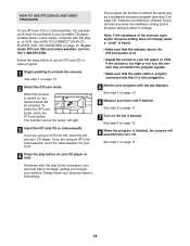
.... See step 5 on page 11. 7 Turn on your CD player or VCR. To select the iFIT.com mode, press the iFIT.com button. If you are using an iFIT.com CD, insert the CD into your personal trainer will be connected to your workout. HOW TO USE IFIT.COM CD AND VIDEO PROGRAMS To use an iFIT.com CD or video program. 1 Begin pedaling to activate the console. Note: If the resistance of...
.... See step 5 on page 11. 7 Turn on your CD player or VCR. To select the iFIT.com mode, press the iFIT.com button. If you are using an iFIT.com CD, insert the CD into your personal trainer will be connected to your workout. HOW TO USE IFIT.COM CD AND VIDEO PROGRAMS To use an iFIT.com CD or video program. 1 Begin pedaling to activate the console. Note: If the resistance of...
English Manual
Page 19
... the button will light. 3 Go to play iFIT.com audio and video programs directly from our Web site. See step 7 on page 10. 2 Select the iFIT.com mode. THE OPTIONAL CHEST PULSE SENSOR The optional chest pulse sensor provides hands-free operation and continuously monitors your heart rate during your exercise equipment without wires or cables. The program will function in almost the same way as a resistance and pace The new NordicTrack® Wireless Workout interactive...
... the button will light. 3 Go to play iFIT.com audio and video programs directly from our Web site. See step 7 on page 10. 2 Select the iFIT.com mode. THE OPTIONAL CHEST PULSE SENSOR The optional chest pulse sensor provides hands-free operation and continuously monitors your heart rate during your exercise equipment without wires or cables. The program will function in almost the same way as a resistance and pace The new NordicTrack® Wireless Workout interactive...
English Manual
Page 20
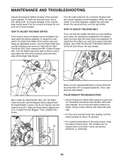
... the Screw. 24 46 Next, turn the Right Pedal (21) counterclockwise and remove it is adjusted to the highest level, the Drive Belt (47) may interfere with the Reed Switch. Do not hold the metal contacts for a moment. MAINTENANCE AND TROUBLESHOOTING Inspect and properly tighten all parts of direct sunlight. PULSE SENSOR TROUBLESHOOTING • Avoid moving your hands while using the pulse sensor. doing so may need to or away from the console...
... the Screw. 24 46 Next, turn the Right Pedal (21) counterclockwise and remove it is adjusted to the highest level, the Drive Belt (47) may interfere with the Reed Switch. Do not hold the metal contacts for a moment. MAINTENANCE AND TROUBLESHOOTING Inspect and properly tighten all parts of direct sunlight. PULSE SENSOR TROUBLESHOOTING • Avoid moving your hands while using the pulse sensor. doing so may need to or away from the console...
English Manual
Page 21
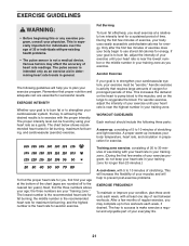
... this or any exercise program, consult your exercise program. The following three parts: A warm-up, consisting of 5 to 10 minutes of the chart (ages are rounded off to 30 minutes of exercising with pre-existing health problems. • The pulse sensor is the heart rate for fat burning, maximum fat burning, and cardiovascular (aerobic) exercise. The chart below shows recommended heart rates for aerobic exercise. Aerobic Exercise If your...
... this or any exercise program, consult your exercise program. The following three parts: A warm-up, consisting of 5 to 10 minutes of the chart (ages are rounded off to 30 minutes of exercising with pre-existing health problems. • The pulse sensor is the heart rate for fat burning, maximum fat burning, and cardiovascular (aerobic) exercise. The chart below shows recommended heart rates for aerobic exercise. Aerobic Exercise If your...
English Manual
Page 22
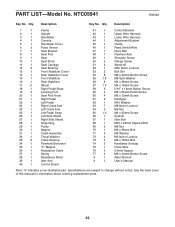
... 1 37 1 38 1 39 1 40 1 Frame Upright Handlebar Console Handlebar Cover Pulse Sensor Seat Bracket Seat Post Seat Seat Knob Seat Carriage Seat Bushing Front Stabilizer Cover Rear Stabilizer Cover Front Stabilizer Rear Stabilizer Wheel Right Pedal Strap Leveling Foot Seat Post Knob Right Pedal Left Pedal Right Crank Arm Left Crank Arm Left Pedal Strap Left Side Shield Right Side Shield Snap Ring Pulley Magnet Crank Assembly Thrust Washer Crank Bearing Flywheel/Generator "C" Magnet Resistance Cable Spring Resistance Motor Idler Arm Control Board 41 1 42 1 43 1 44 1 45...
... 1 37 1 38 1 39 1 40 1 Frame Upright Handlebar Console Handlebar Cover Pulse Sensor Seat Bracket Seat Post Seat Seat Knob Seat Carriage Seat Bushing Front Stabilizer Cover Rear Stabilizer Cover Front Stabilizer Rear Stabilizer Wheel Right Pedal Strap Leveling Foot Seat Post Knob Right Pedal Left Pedal Right Crank Arm Left Crank Arm Left Pedal Strap Left Side Shield Right Side Shield Snap Ring Pulley Magnet Crank Assembly Thrust Washer Crank Bearing Flywheel/Generator "C" Magnet Resistance Cable Spring Resistance Motor Idler Arm Control Board 41 1 42 1 43 1 44 1 45...

English Manual
Page 24
... MODEL NUMBER of the product (NTC05941) • the NAME of the product (NordicTrack® SL 705 exercise cycle) • the SERIAL NUMBER of the product (see the front cover of this manual) • the KEY NUMBER and DESCRIPTION of the part(s) (see pages 22 and 23) LIMITED WARRANTY WHAT IS COVERED-The entire NordicTrack® SL 705 exercise cycle ("Product") is warranted to be free of this limited warranty...
... MODEL NUMBER of the product (NTC05941) • the NAME of the product (NordicTrack® SL 705 exercise cycle) • the SERIAL NUMBER of the product (see the front cover of this manual) • the KEY NUMBER and DESCRIPTION of the part(s) (see pages 22 and 23) LIMITED WARRANTY WHAT IS COVERED-The entire NordicTrack® SL 705 exercise cycle ("Product") is warranted to be free of this limited warranty...


