Service Manual
Page 43
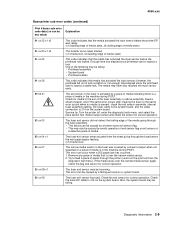
...POST. This error can be failing: • Printhead assembly • System board • Printhead cables This code indicates that media has activated the input sensor; Try to expect a stable lock. Diagnostic information 2-9 4060-xxx Base printer sub error codes (continued) First 6 bytes sub error code data (xx can... the printer (could run the print test from the sheet going through the fuser assembly. • This failure can occur when a 202 paper jam has occurred. 1. Enough time has elapsed since the printhead start to J14 on the system board. The fuser exit...
...POST. This error can be failing: • Printhead assembly • System board • Printhead cables This code indicates that media has activated the input sensor; Try to expect a stable lock. Diagnostic information 2-9 4060-xxx Base printer sub error codes (continued) First 6 bytes sub error code data (xx can... the printer (could run the print test from the sheet going through the fuser assembly. • This failure can occur when a 202 paper jam has occurred. 1. Enough time has elapsed since the printhead start to J14 on the system board. The fuser exit...
Service Manual
Page 64
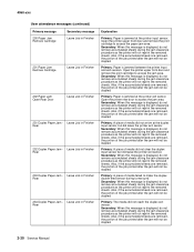
... of the job printed after the jam will not reprint the removed sheets. Secondary: When this message is jammed at the printer input sensor. 4060-xxx User attendance messages (continued) Primary message 200 Paper Jam Remove Cartridge Secondary message Leave Job in Finisher 201 Paper Jam Remove... Cartridge Leave Job in Finisher 202 Paper Jam Open Rear Door Leave Job in Finisher Rear 233 Duplex Paper Jam - Leave Job in Finisher 231 Duplex Paper Jam - ...
... of the job printed after the jam will not reprint the removed sheets. Secondary: When this message is jammed at the printer input sensor. 4060-xxx User attendance messages (continued) Primary message 200 Paper Jam Remove Cartridge Secondary message Leave Job in Finisher 201 Paper Jam Remove... Cartridge Leave Job in Finisher 202 Paper Jam Open Rear Door Leave Job in Finisher Rear 233 Duplex Paper Jam - Leave Job in Finisher 231 Duplex Paper Jam - ...
Service Manual
Page 97
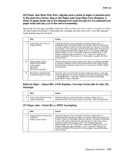
... gears, clutch and other linkage parts for correct operation, binding, broken parts, or interference from the sensor cable. If this does not fix the problem, replace the lower control board. A 202 paper jam message can help isolate the problem. If this does not fix the problem, replace the ...necessary. If incorrect, repair as necessary. The voltage measures approximately 0 V dc. 4060-xxx 202 Paper Jam Open Rear Door displays and a sheet of paper is jammed prior to the pass thru sensor flag or 202 Paper Jam Open Rear Door displays, a sheet of paper feeds out to J3 on the...
... gears, clutch and other linkage parts for correct operation, binding, broken parts, or interference from the sensor cable. If this does not fix the problem, replace the lower control board. A 202 paper jam message can help isolate the problem. If this does not fix the problem, replace the ...necessary. If incorrect, repair as necessary. The voltage measures approximately 0 V dc. 4060-xxx 202 Paper Jam Open Rear Door displays and a sheet of paper is jammed prior to the pass thru sensor flag or 202 Paper Jam Open Rear Door displays, a sheet of paper feeds out to J3 on the...
Service Manual
Page 107
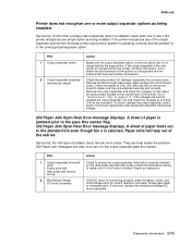
... autoconnects of the redrive. If incorrect, replace the output expander assembly mechanical linkage. 202 Paper Jam Open Rear Door message displays. 4060-xxx Printer does not recognize one to the pass thru sensor flag. 202 Paper Jam Open Rear Door message displays. If the output expander is not loose ...or broken. If the voltages are attached securely and correctly. They can help isolate the problem. 202 Paper Jam messages can also occur prior ...
... autoconnects of the redrive. If incorrect, replace the output expander assembly mechanical linkage. 202 Paper Jam Open Rear Door message displays. 4060-xxx Printer does not recognize one to the pass thru sensor flag. 202 Paper Jam Open Rear Door message displays. If the output expander is not loose ...or broken. If the voltages are attached securely and correctly. They can help isolate the problem. 202 Paper Jam messages can also occur prior ...
Service Manual
Page 150
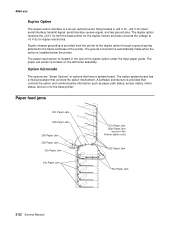
... a ground spring attached to the frame and base of the duplex option under the input paper guide. The paper exit sensor is located in the finisher option only) 202 Paper Jam 23x Paper Jam 3-22 Service Manual Paper feed jams 201 Paper Jam 200 Paper Jam 260 Paper Jam 250 ... when the option is provided from the base printer for the duplex motors and also converts the voltage to the base printer. The paper input sensor is located on to +5 V dc for duplex electronics. A software architecture is a six pin autoconnector that provides a +24 V dc, +24 V dc return, serial interface ...
... a ground spring attached to the frame and base of the duplex option under the input paper guide. The paper exit sensor is located in the finisher option only) 202 Paper Jam 23x Paper Jam 3-22 Service Manual Paper feed jams 201 Paper Jam 200 Paper Jam 260 Paper Jam 250 ... when the option is provided from the base printer for the duplex motors and also converts the voltage to the base printer. The paper input sensor is located on to +5 V dc for duplex electronics. A software architecture is a six pin autoconnector that provides a +24 V dc, +24 V dc return, serial interface ...
Service Manual
Page 151
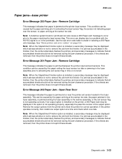
...can be displayed which advises whether or not to activating the input sensor flag, the sensor not detecting paper over the sensor, or paper arriving at the printer input sensor. See "Base printer sub error codes" on the printer, a 202 Paper Jam may be removed during the jam clearance procedure. Note...the fuser assembly in the printhead. Error Message 201 Paper Jam - If an output option is not operating properly, especially the pass thru sensor of the output option. If the sheets are removed, then the printer does not reprint these sheets. Diagnostic aids 3-23 If a job...
...can be displayed which advises whether or not to activating the input sensor flag, the sensor not detecting paper over the sensor, or paper arriving at the printer input sensor. See "Base printer sub error codes" on the printer, a 202 Paper Jam may be removed during the jam clearance procedure. Note...the fuser assembly in the printhead. Error Message 201 Paper Jam - If an output option is not operating properly, especially the pass thru sensor of the output option. If the sheets are removed, then the printer does not reprint these sheets. Diagnostic aids 3-23 If a job...
Service Manual
Page 182
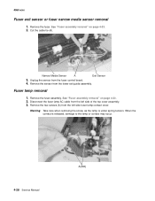
... removing the screw, as the lamp is released, damage to the lamp or contact may occur. 4-28 Service Manual A(202) Remove the fuser. When the contact is under spring tension. Unplug the sensor from the left side of the top cover assembly. 3. Fuser lamp removal 1. See "Fuser assembly removal" on page 4-23...
... removing the screw, as the lamp is released, damage to the lamp or contact may occur. 4-28 Service Manual A(202) Remove the fuser. When the contact is under spring tension. Unplug the sensor from the left side of the top cover assembly. 3. Fuser lamp removal 1. See "Fuser assembly removal" on page 4-23...
Service Manual
Page 206
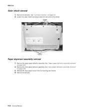
Remove the inner paper deflector assembly. Loosen the outer shield mounting screws (A) and remove the shield. Remove the left door. A(202) A(202) Paper alignment assembly removal 1. See "Inner paper deflector assembly removal" on page 4-63. 2. Release the input paper sensor from its mounting and remove. 4. Remove the left door. 4-52 Service Manual See "Upper paper deflector assembly removal" on page 4-33. 3. See "Left door removal" on page 4-9. 2. 4060-xxx Outer shield removal 1. Remove the upper paper deflector assembly.
Remove the inner paper deflector assembly. Loosen the outer shield mounting screws (A) and remove the shield. Remove the left door. A(202) A(202) Paper alignment assembly removal 1. See "Inner paper deflector assembly removal" on page 4-63. 2. Release the input paper sensor from its mounting and remove. 4. Remove the left door. 4-52 Service Manual See "Upper paper deflector assembly removal" on page 4-33. 3. See "Left door removal" on page 4-9. 2. 4060-xxx Outer shield removal 1. Remove the upper paper deflector assembly.
Service Manual
Page 325
... adjustment 4-4 parts catalog 7-16 removal 4-52 4060-xxx autocompensator, integrated tray parts catalog 7-13 pick roll installation 4-39 removal 4-35 autoconnect connections, top 5-1 B base sensor test 3-16 bevel gear installation 4-17 removal 4-16 bezel, operator panel removal 4-49 button test 3-8 C cable diagrams 7-34, 7-36, 7-38 cables cover closed switch...Check Finisher 2-32 281 Paper Jam - Remove Cartridge 2-30 201 Paper Jam - Open Rear Door 2-30 231 Duplex Paper Jam - Remove Cartridge 2-30 202 Paper Jam - Check Finisher 2-32 282 Staple Jam - Front 2-31 237 Duplex Paper Jam -
... adjustment 4-4 parts catalog 7-16 removal 4-52 4060-xxx autocompensator, integrated tray parts catalog 7-13 pick roll installation 4-39 removal 4-35 autoconnect connections, top 5-1 B base sensor test 3-16 bevel gear installation 4-17 removal 4-16 bezel, operator panel removal 4-49 button test 3-8 C cable diagrams 7-34, 7-36, 7-38 cables cover closed switch...Check Finisher 2-32 281 Paper Jam - Remove Cartridge 2-30 201 Paper Jam - Open Rear Door 2-30 231 Duplex Paper Jam - Remove Cartridge 2-30 202 Paper Jam - Check Finisher 2-32 282 Staple Jam - Front 2-31 237 Duplex Paper Jam -


