Lenovo K4 Series User Guide V1.0
Page 7
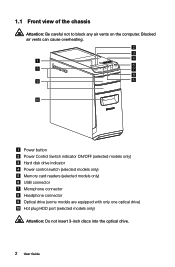
1.1 Front view of the chassis Attention: Be careful not to block any air vents on the computer. Blocked air vents can cause overheating. Power button Power Control Switch indicator ON/OFF (selected models only) Hard disk drive indicator Power control switch (selected models only) Memory card readers (selected models only) USB connector Microphone connector Headphone connector Optical drive (some models are equipped with only one optical drive) Hot plug HDD port (selected models only) Attention: Do not insert 3-inch discs into the optical drive. 2 User Guide
1.1 Front view of the chassis Attention: Be careful not to block any air vents on the computer. Blocked air vents can cause overheating. Power button Power Control Switch indicator ON/OFF (selected models only) Hard disk drive indicator Power control switch (selected models only) Memory card readers (selected models only) USB connector Microphone connector Headphone connector Optical drive (some models are equipped with only one optical drive) Hot plug HDD port (selected models only) Attention: Do not insert 3-inch discs into the optical drive. 2 User Guide
Lenovo K4 Series User Guide V1.0
Page 34
Chapter Hardware Replacement Guide This chapter contains the following topics: Identifying internal components Identifying parts on the system board Removing the computer cover Removing the front bezel Replacing a memory module Replacing a hard disk drive Replacing an optical drive Replacing a graphics card Replacing the TV-Tuner card Replacing the keyboard and mouse User Guide 29
Chapter Hardware Replacement Guide This chapter contains the following topics: Identifying internal components Identifying parts on the system board Removing the computer cover Removing the front bezel Replacing a memory module Replacing a hard disk drive Replacing an optical drive Replacing a graphics card Replacing the TV-Tuner card Replacing the keyboard and mouse User Guide 29
Lenovo K4 Series User Guide V1.0
Page 35
...copy of the TV-Tuner card in this guide, CRUs and FRUs will often be obtained online from the Lenovo® Support Web site at: http://consumersupport.lenovo.com. 30 User Guide Note: Trained service personnel should refer to as trained service personnel who are replacing ... card. This guide contains instructions for replacing the following parts: • Memory modules • Hard disk drive • Optical disk drive • Graphics card • TV-Tuner card Safety information for step-by Lenovo®. The description of the Safety and Warranty Guide can also be referred...
...copy of the TV-Tuner card in this guide, CRUs and FRUs will often be obtained online from the Lenovo® Support Web site at: http://consumersupport.lenovo.com. 30 User Guide Note: Trained service personnel should refer to as trained service personnel who are replacing ... card. This guide contains instructions for replacing the following parts: • Memory modules • Hard disk drive • Optical disk drive • Graphics card • TV-Tuner card Safety information for step-by Lenovo®. The description of the Safety and Warranty Guide can also be referred...

Lenovo K4 Series User Guide V1.0
Page 37
... its anti-static packaging and install it . • Do not place parts on the computer cover or other computer components with care, and handle adapters, memory modules, system boards, and microprocessors by their edges. This will reduce static electricity in order to install the new part. When replacing a part, do not...
... its anti-static packaging and install it . • Do not place parts on the computer cover or other computer components with care, and handle adapters, memory modules, system boards, and microprocessors by their edges. This will reduce static electricity in order to install the new part. When replacing a part, do not...
Lenovo K4 Series User Guide V1.0
Page 39
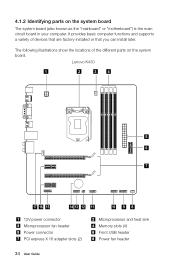
... locations of devices that are factory-installed or that you can install later. Lenovo K430 1 2 3 4 5 6 7 17 16 15 14 13 12 11 10 9 8 12V power connector Microprocessor fan header Power connector PCI express X 16 adapter slots (2) Microprocessor and heat sink Memory slots (4) Front USB header Power fan header 34 User Guide It provides...
... locations of devices that are factory-installed or that you can install later. Lenovo K430 1 2 3 4 5 6 7 17 16 15 14 13 12 11 10 9 8 12V power connector Microprocessor fan header Power connector PCI express X 16 adapter slots (2) Microprocessor and heat sink Memory slots (4) Front USB header Power fan header 34 User Guide It provides...
Lenovo K4 Series User Guide V1.0
Page 40
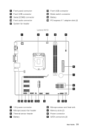
Front panel connector Front USB connector Serial (COM2) connector Front audio connector System fan header Front USB connector Mode switch connector Battery PCI express X 1 adapter slots (2) Lenovo K410 1 2 3 4 5 6 7 8 9 20 19 18 17 16 15 14 13 12V power connector Microprocessor fan header Thermal sensor header Battery 12 11 10 Microprocessor and heat sink Memory slots (2) Power connector SATA connectors (3) User Guide 35
Front panel connector Front USB connector Serial (COM2) connector Front audio connector System fan header Front USB connector Mode switch connector Battery PCI express X 1 adapter slots (2) Lenovo K410 1 2 3 4 5 6 7 8 9 20 19 18 17 16 15 14 13 12V power connector Microprocessor fan header Thermal sensor header Battery 12 11 10 Microprocessor and heat sink Memory slots (2) Power connector SATA connectors (3) User Guide 35
Lenovo K4 Series User Guide V1.0
Page 43
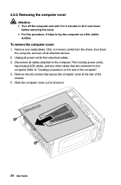
To remove the computer cover: 1. This includes power cords, input/output (I/O) cables, and any media (disks, CDs, or memory cards) from electrical outlets. 3. Remove the two screws that are connected to the computer. Slide the computer cover out to remove it helps to lay ...
To remove the computer cover: 1. This includes power cords, input/output (I/O) cables, and any media (disks, CDs, or memory cards) from electrical outlets. 3. Remove the two screws that are connected to the computer. Slide the computer cover out to remove it helps to lay ...
Lenovo K4 Series User Guide V1.0
Page 45
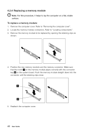
... be replaced by opening the retaining clips as shown. 4. Locate the memory module connectors. Make sure that the notch on the memory module aligns correctly with the connector key on a flat, stable surface. Position the new memory module over the memory connector. Remove the memory module to "Removing the computer cover". 2. Remove the computer cover...
... be replaced by opening the retaining clips as shown. 4. Locate the memory module connectors. Make sure that the notch on the memory module aligns correctly with the connector key on a flat, stable surface. Position the new memory module over the memory connector. Remove the memory module to "Removing the computer cover". 2. Remove the computer cover...
Lenovo K4 Series User Guide V1.0
Page 53
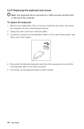
... be replaced using the same method. 48 User Guide Locate the connector for the keyboard. To replace the keyboard: 1. Remove any media (disks, CDs, or memory cards) from the drives, shut down the computer, and turn off all power cords from the computer and connect the new keyboard cable to the...
... be replaced using the same method. 48 User Guide Locate the connector for the keyboard. To replace the keyboard: 1. Remove any media (disks, CDs, or memory cards) from the drives, shut down the computer, and turn off all power cords from the computer and connect the new keyboard cable to the...


