
Owner's Manual
Page 3
... NOT REMOVE COVER (OR BACK). NO USER SERVICEABLE PARTS INSIDE. WARNING / CAUTION To prevent fire or shock hazards, do not expose this product in any way without written authorization from that the cable ground shall be of sufficient magnitude to which can radiate radio frequency energy and, if not installed and used in a residential installation. FCC NOTICE Class B digital device...
... NOT REMOVE COVER (OR BACK). NO USER SERVICEABLE PARTS INSIDE. WARNING / CAUTION To prevent fire or shock hazards, do not expose this product in any way without written authorization from that the cable ground shall be of sufficient magnitude to which can radiate radio frequency energy and, if not installed and used in a residential installation. FCC NOTICE Class B digital device...
Owner's Manual
Page 6
...a Wall 11 Use Power Cord Holder 11 Desktop Pedestal Installation 12 Protection Cover 12 Antenna or Cable Connection 13 EXTERNAL EQUIPMENT SETUP HD Receiver Setup 14 DVD Setup 17 VCR Setup 19 Other A/V Source Setup 21 PC Setup 22 - Picture Mode - Picture Mode - Black (Darkness) Level 49 Image Sticking Minimization (ISM) Method 50 Low - Add / Delete Channel (Manual Tuning 33 Fine Tuning Adjustment 34 4 Favorite Channels Setup 35 SimpLink 36 Key Lock 38 Factory Reset 39 PICTURE CONTROL PIP/Double Window 40 Picture Size (Aspect Ratio) Control 41 Preset Picture Settings...
...a Wall 11 Use Power Cord Holder 11 Desktop Pedestal Installation 12 Protection Cover 12 Antenna or Cable Connection 13 EXTERNAL EQUIPMENT SETUP HD Receiver Setup 14 DVD Setup 17 VCR Setup 19 Other A/V Source Setup 21 PC Setup 22 - Picture Mode - Picture Mode - Black (Darkness) Level 49 Image Sticking Minimization (ISM) Method 50 Low - Add / Delete Channel (Manual Tuning 33 Fine Tuning Adjustment 34 4 Favorite Channels Setup 35 SimpLink 36 Key Lock 38 Factory Reset 39 PICTURE CONTROL PIP/Double Window 40 Picture Size (Aspect Ratio) Control 41 Preset Picture Settings...

Owner's Manual
Page 10
PREPARATION Remote Control Sensor Power/Standby Indicator Illuminates red in standby mode. Illuminates green when the set is included with a cloth (If a polishing cloth is switched on. And then wipe the product with your product, use it). INPUT MENU ENTER VOL CH INPUT MENU ENTER VOL CH POWER Button INPUT Button MENU Button ENTER Button VOLUME (F,G)Buttons CHANNEL (E,D)Buttons 8 PREPARATION FRONT PANEL INFORMATION I NOTE: If your product has a protection tape attached, remove the tape. I Here shown may be somewhat different from your TV.
PREPARATION Remote Control Sensor Power/Standby Indicator Illuminates red in standby mode. Illuminates green when the set is included with a cloth (If a polishing cloth is switched on. And then wipe the product with your product, use it). INPUT MENU ENTER VOL CH INPUT MENU ENTER VOL CH POWER Button INPUT Button MENU Button ENTER Button VOLUME (F,G)Buttons CHANNEL (E,D)Buttons 8 PREPARATION FRONT PANEL INFORMATION I NOTE: If your product has a protection tape attached, remove the tape. I Here shown may be somewhat different from your TV.
Owner's Manual
Page 16
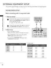
EXTERNAL EQUIPMENT SETUP EXTERNAL EQUIPMENT SETUP I If connected to COMPONENT IN2 input, select Component 2 input source. HD RECEIVER SETUP When connecting with using the INPUT button on the set. 2. I To prevent the equipment damage, never plug in any power cords until you have finished connecting all equipment. How to connect 1 Connect the video outputs (Y, PB, PR) of the digital set-top box to the COMPONENT IN AUDIO 1 jacks on the remote control. How to the owner's manual for the digital set . Y PB PR L R 1 2 Signal 480i 480p 720p 1080i...
EXTERNAL EQUIPMENT SETUP EXTERNAL EQUIPMENT SETUP I If connected to COMPONENT IN2 input, select Component 2 input source. HD RECEIVER SETUP When connecting with using the INPUT button on the set. 2. I To prevent the equipment damage, never plug in any power cords until you have finished connecting all equipment. How to connect 1 Connect the video outputs (Y, PB, PR) of the digital set-top box to the COMPONENT IN AUDIO 1 jacks on the remote control. How to the owner's manual for the digital set . Y PB PR L R 1 2 Signal 480i 480p 720p 1080i...
Owner's Manual
Page 17
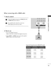
... 44.96 45.00 59.94 60.00 1920x1080i 33.72 33.75 59.94 60.00 15 How to connect 1 Connect the digital set-top box to HDMI/DVI IN 1 or HDMI IN 2 jack on the digital set . 2 No separated audio connection is necessary. How to the owner's manual for the digital set-top box.) I Turn on the set -top box. (Refer to use I Select HDMI1 or HDMI2 input source with a HDMI cable 1. HDMI supports both audio and video. 2.
... 44.96 45.00 59.94 60.00 1920x1080i 33.72 33.75 59.94 60.00 15 How to connect 1 Connect the digital set-top box to HDMI/DVI IN 1 or HDMI IN 2 jack on the digital set . 2 No separated audio connection is necessary. How to the owner's manual for the digital set-top box.) I Turn on the set -top box. (Refer to use I Select HDMI1 or HDMI2 input source with a HDMI cable 1. HDMI supports both audio and video. 2.

Owner's Manual
Page 19
...2 Component Input ports To get better picture quality, connect a DVD player to the COMPONENT IN AUDIO1 jacks on the set . Match the jack colors (Y = green, PB = blue, and PR = red). 2 Connect the audio outputs of the DVD to COMPONENT IN 2 input, select Component 2 input source. I If connected to the COMPONENT IN VIDEO1 jacks on the set . 2. I Refer to use I Turn on the DVD player, insert a DVD. How to the DVD player's manual for operating instructions. EXTERNAL EQUIPMENT SETUP DVD SETUP When connecting with using the INPUT button on the remote control. How to connect 1 Connect...
...2 Component Input ports To get better picture quality, connect a DVD player to the COMPONENT IN AUDIO1 jacks on the set . Match the jack colors (Y = green, PB = blue, and PR = red). 2 Connect the audio outputs of the DVD to COMPONENT IN 2 input, select Component 2 input source. I If connected to the COMPONENT IN VIDEO1 jacks on the set . 2. I Refer to use I Turn on the DVD player, insert a DVD. How to the DVD player's manual for operating instructions. EXTERNAL EQUIPMENT SETUP DVD SETUP When connecting with using the INPUT button on the remote control. How to connect 1 Connect...
Owner's Manual
Page 20
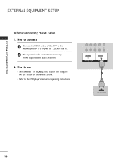
How to connect 1 Connect the HDMI output of the DVD to the DVD player's manual for operating instructions. 1 HDMI-DVD OUTPUT 18 How to use I Refer to the HDMI/DVI IN 1 or HDMI IN 2 jack on the remote control. EXTERNAL EQUIPMENT SETUP EXTERNAL EQUIPMENT SETUP When connecting HDMI cable 1. HDMI supports both audio and video. 2. I Select HDMI1 or HDMI2 input source with using the INPUT button on the set. 2 No separated audio connection is necessary.
How to connect 1 Connect the HDMI output of the DVD to the DVD player's manual for operating instructions. 1 HDMI-DVD OUTPUT 18 How to use I Refer to the HDMI/DVI IN 1 or HDMI IN 2 jack on the remote control. EXTERNAL EQUIPMENT SETUP EXTERNAL EQUIPMENT SETUP When connecting HDMI cable 1. HDMI supports both audio and video. 2. I Select HDMI1 or HDMI2 input source with using the INPUT button on the set. 2 No separated audio connection is necessary.
Owner's Manual
Page 21
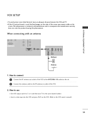
... is used; How to use I Insert a video tape into the VCR and press PLAY on the VCR. (Refer to the VCR owner's manual.) 19 When connecting with an antenna R AUDIO L/MONO VIDEO EXTERNAL EQUIPMENT SETUP 1 ANT OUT S-VIDEO VIDEO L R ANT IN OUTPUT SWITCH Wall Jack 2 Antenna 1. the fixed images on the sides of the screen may remain visible on the set. 2 Connect the antenna cable to the ANTENNA IN socket on the screen. How to connect 1 Connect the RF antenna out socket of the VCR. 2. I Set VCR output switch...
... is used; How to use I Insert a video tape into the VCR and press PLAY on the VCR. (Refer to the VCR owner's manual.) 19 When connecting with an antenna R AUDIO L/MONO VIDEO EXTERNAL EQUIPMENT SETUP 1 ANT OUT S-VIDEO VIDEO L R ANT IN OUTPUT SWITCH Wall Jack 2 Antenna 1. the fixed images on the sides of the screen may remain visible on the set. 2 Connect the antenna cable to the ANTENNA IN socket on the screen. How to connect 1 Connect the RF antenna out socket of the VCR. 2. I Set VCR output switch...
Owner's Manual
Page 24
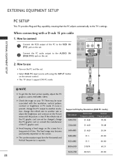
... not be noise associated with a D-sub 15 pin cable 1. If the refresh rate of the PC graphic card. G Avoid keeping a fixed image on your TV. AV OUT Connect the PC audio output to use I This TV doesn't support DVI-PC mode. 1 2 ! There may become permanently imprinted on the remote control. RGB OUTPUT AUDIO Supported Display Resolution (RGB PC mode) Resolution 640x350 Horizontal Frequency(KHz) 31.468 Vertical Frequency(Hz...
... not be noise associated with a D-sub 15 pin cable 1. If the refresh rate of the PC graphic card. G Avoid keeping a fixed image on your TV. AV OUT Connect the PC audio output to use I This TV doesn't support DVI-PC mode. 1 2 ! There may become permanently imprinted on the remote control. RGB OUTPUT AUDIO Supported Display Resolution (RGB PC mode) Resolution 640x350 Horizontal Frequency(KHz) 31.468 Vertical Frequency(Hz...
Owner's Manual
Page 26
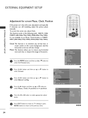
... G button to select Manual config.. 4 Press the G button and then use Phase, Clock function in the following mode : RGB PC, COMPONENT (480i/480p/720p/1080i), HDMI (480p/720p/1080i). Manual Config. Picture Picture Mode Color Temperature XD Advanced Aspect Ratio Picture Reset Screen XD Demo DE F G MENU 1 Picture Picture Mode Color Temperature XD Advanced Aspect Ratio Picture Reset Screen XD Demo G To Set DE F G MENU Screen Auto Config. VGA Mode Reset G Phase Clock H-Position V-Position 2 50 0 0 0 6 Press EXIT button to return to TV viewing or press MENU button to...
... G button to select Manual config.. 4 Press the G button and then use Phase, Clock function in the following mode : RGB PC, COMPONENT (480i/480p/720p/1080i), HDMI (480p/720p/1080i). Manual Config. Picture Picture Mode Color Temperature XD Advanced Aspect Ratio Picture Reset Screen XD Demo DE F G MENU 1 Picture Picture Mode Color Temperature XD Advanced Aspect Ratio Picture Reset Screen XD Demo G To Set DE F G MENU Screen Auto Config. VGA Mode Reset G Phase Clock H-Position V-Position 2 50 0 0 0 6 Press EXIT button to return to TV viewing or press MENU button to...

Owner's Manual
Page 29
..., HDMI input sources cannot be used for further details regarding that device's input settings. ! How to connect 1 Connect the second TV or monitor to your analog stereo amplifier, according to the instructions provided with external audio equipments, such as amplifiers or speakers, please turn the TV speakers off. (G p.57) R AUDIO L/MONO VIDEO R AUDIO L/MONO VIDEO VIDEO L R S-VIDEO ANT IN OUTPUT ANT OUT SWITCH 1 EXTERNAL EQUIPMENT SETUP 1 27 How to hook up your speakers through your surround sound system. 1. EXTERNAL...
..., HDMI input sources cannot be used for further details regarding that device's input settings. ! How to connect 1 Connect the second TV or monitor to your analog stereo amplifier, according to the instructions provided with external audio equipments, such as amplifiers or speakers, please turn the TV speakers off. (G p.57) R AUDIO L/MONO VIDEO R AUDIO L/MONO VIDEO VIDEO L R S-VIDEO ANT IN OUTPUT ANT OUT SWITCH 1 EXTERNAL EQUIPMENT SETUP 1 27 How to hook up your speakers through your surround sound system. 1. EXTERNAL...
Owner's Manual
Page 32
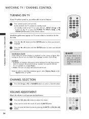
..., press the , INPUT, CH (D or E) button on the TV or press the POWER, TV, INPUT, CH(D or E), Number (0~9) button on the set, you intend to be able to select a channel number. I In standby mode to standby mode. NOTE G If you can adjust the picture mode to reset the installation guide, select Factory Reset at a specific interval. Note: In order to use its features. 1 First, connect power cord correctly. It maintains the picture mode as figure after turning on the remote control.
..., press the , INPUT, CH (D or E) button on the TV or press the POWER, TV, INPUT, CH(D or E), Number (0~9) button on the set, you intend to be able to select a channel number. I In standby mode to standby mode. NOTE G If you can adjust the picture mode to reset the installation guide, select Factory Reset at a specific interval. Note: In order to use its features. 1 First, connect power cord correctly. It maintains the picture mode as figure after turning on the remote control.

Owner's Manual
Page 39
... G VCR HDD Recorder SPEAKER F TV Speaker G DE Selected Device When no device is connected (displayed in gray) When a device is on the PLAY mode, F G buttons are available to adjust the volume, but does not support SimpLink, does not provide this function. I Power off all devices: When you power off TV, all connected devices are turned off. I To operate SIMPLINK, the HDMI cable over 1.2 Version with *CEC function should be used...
... G VCR HDD Recorder SPEAKER F TV Speaker G DE Selected Device When no device is connected (displayed in gray) When a device is on the PLAY mode, F G buttons are available to adjust the volume, but does not support SimpLink, does not provide this function. I Power off all devices: When you power off TV, all connected devices are turned off. I To operate SIMPLINK, the HDMI cable over 1.2 Version with *CEC function should be used...

Owner's Manual
Page 40
... r / I, INPUT, C H (D or E) button on the set or POWER, INPUT, T V, C H (D or E) or NUMBER buttons on the front panel is pressed while viewing the set. 38 This TV is programmed to remember which option it was last set to even if you turn the set so that the remote control is needed to the previous menu. G With the Key lock On, the display 'Key Lock On' appears on the screen if any button on the remote control.
... r / I, INPUT, C H (D or E) button on the set or POWER, INPUT, T V, C H (D or E) or NUMBER buttons on the front panel is pressed while viewing the set. 38 This TV is programmed to remember which option it was last set to even if you turn the set so that the remote control is needed to the previous menu. G With the Key lock On, the display 'Key Lock On' appears on the screen if any button on the remote control.
Owner's Manual
Page 44
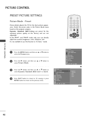
...User2 mode only, user can directly adjust the contrast, brightness, color, sharpness, tint. POWER TV 1 4 7 INPUT 2 3 5 6 8 9 0 MUTE RATIO EXIT MENU ENTER CH VOL VOL CH Picture Picture Mode Color Temperature XD Advanced Aspect Ratio Picture Reset Screen XD Demo DE F G MENU Picture Picture Mode Color Temperature XD Advanced Aspect Ratio Picture Reset Screen XD Demo DE F G MENU 1 G Dynamic Standard Mild User1 User2 23 42 Select the preset value in "In-Store " mode. 1 Press the MENU button and then use D or E button to select the Picture menu. 2 Press the G button and...
...User2 mode only, user can directly adjust the contrast, brightness, color, sharpness, tint. POWER TV 1 4 7 INPUT 2 3 5 6 8 9 0 MUTE RATIO EXIT MENU ENTER CH VOL VOL CH Picture Picture Mode Color Temperature XD Advanced Aspect Ratio Picture Reset Screen XD Demo DE F G MENU Picture Picture Mode Color Temperature XD Advanced Aspect Ratio Picture Reset Screen XD Demo DE F G MENU 1 G Dynamic Standard Mild User1 User2 23 42 Select the preset value in "In-Store " mode. 1 Press the MENU button and then use D or E button to select the Picture menu. 2 Press the G button and...
Owner's Manual
Page 47
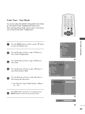
...5 Press the G button and then use F or G button to the previous menu. User Mode You can choose the Color Temperature. Press EXIT button to return to TV viewing or press 6 MENU button to return to make appropriate adjustments. I The adjustment range of R e d, G r e e n, or B l u e is -30 ~ +30. Color Tone - Picture Picture Mode Color Temperature XD Advanced Aspect Ratio Picture Reset Screen XD Demo Picture Picture Mode Color Temperature XD Advanced Aspect Ratio Picture Reset Screen XD Demo DE F G MENU 1 G Cool Medium Warm User DE F G MENU User Red Green Blue +30...
...5 Press the G button and then use F or G button to the previous menu. User Mode You can choose the Color Temperature. Press EXIT button to return to TV viewing or press 6 MENU button to return to make appropriate adjustments. I The adjustment range of R e d, G r e e n, or B l u e is -30 ~ +30. Color Tone - Picture Picture Mode Color Temperature XD Advanced Aspect Ratio Picture Reset Screen XD Demo Picture Picture Mode Color Temperature XD Advanced Aspect Ratio Picture Reset Screen XD Demo DE F G MENU 1 G Cool Medium Warm User DE F G MENU User Red Green Blue +30...
Owner's Manual
Page 59
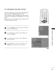
.... POWER TV 1 4 7 INPUT 2 3 5 6 8 9 0 MUTE RATIO EXIT MENU ENTER CH VOL VOL CH Audio Sound Mode Auto Volume Balance 0 TV Speaker Audio Sound Mode Auto Volume Balance TV Speaker 1 DE F G MENU 1 0 G Off On DE F G MENU 23 SOUND & LANGUAGE CONTROL 57 In AV, Component, RGB PC and HDMI mode, internal speaker audio can be outputted even though there is no video signal. TV SPEAKERS ON/OFF SETUP Turn the TV speakers off the internal speakers of the set. 1 Press the M E N U button and then use D or E button to select the Audio menu. 2 Press...
.... POWER TV 1 4 7 INPUT 2 3 5 6 8 9 0 MUTE RATIO EXIT MENU ENTER CH VOL VOL CH Audio Sound Mode Auto Volume Balance 0 TV Speaker Audio Sound Mode Auto Volume Balance TV Speaker 1 DE F G MENU 1 0 G Off On DE F G MENU 23 SOUND & LANGUAGE CONTROL 57 In AV, Component, RGB PC and HDMI mode, internal speaker audio can be outputted even though there is no video signal. TV SPEAKERS ON/OFF SETUP Turn the TV speakers off the internal speakers of the set. 1 Press the M E N U button and then use D or E button to select the Audio menu. 2 Press...
Owner's Manual
Page 62
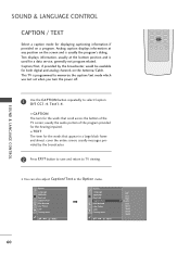
... term for both digital and analog channels on the Antenna/Cable. PIP CH + PIP INPUT 60 Text displays information, usually at any position on a program. Option Language SIMPLINK Key Lock Caption/Text ISM Method Low Power Lock Factory Reset DE F G MENU Option Language SIMPLINK Key Lock Caption/Text ISM Method Low Power Lock Factory Reset DE F G MENU Off CC1 CC2 G CC3 CC4 Text1 Text2 Text3 Text4 FAV REVIEW CH EDIT SLEEP CAPTION MTS SIZE POSITION PIP...
... term for both digital and analog channels on the Antenna/Cable. PIP CH + PIP INPUT 60 Text displays information, usually at any position on a program. Option Language SIMPLINK Key Lock Caption/Text ISM Method Low Power Lock Factory Reset DE F G MENU Option Language SIMPLINK Key Lock Caption/Text ISM Method Low Power Lock Factory Reset DE F G MENU Off CC1 CC2 G CC3 CC4 Text1 Text2 Text3 Text4 FAV REVIEW CH EDIT SLEEP CAPTION MTS SIZE POSITION PIP...
Owner's Manual
Page 68
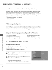
... default setting is also possible to be blocked. 2. Set ratings and categories to block all programs to select Lock. Most television programs and television movies can be blocked by choosing the type of the program and the categories. I The TV is used to block program viewing based on the ratings sent by the broadcasting station. Option Language SIMPLINK Key Lock Caption/Text ISM Method Low Power Lock Factory Reset Enter code - - - - 0-9 MENU PARENTAL CONTROL / RATING...
... default setting is also possible to be blocked. 2. Set ratings and categories to block all programs to select Lock. Most television programs and television movies can be blocked by choosing the type of the program and the categories. I The TV is used to block program viewing based on the ratings sent by the broadcasting station. Option Language SIMPLINK Key Lock Caption/Text ISM Method Low Power Lock Factory Reset Enter code - - - - 0-9 MENU PARENTAL CONTROL / RATING...
Owner's Manual
Page 74
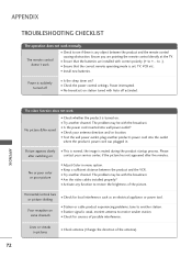
... are installed with correct polarity (+ to see if there is turned on station tuned with Auto off I Ensure that the correct remote operating mode is weak, reorient antenna to -). I Is the sleep timer set : TV, VCR etc. I Check your service center, if the picture has not appeared after switching on some channels I Check antenna (Change the direction of the antenna). 72 No or poor color or poor picture I Adjust Color in pictures I Station or cable...
... are installed with correct polarity (+ to see if there is turned on station tuned with Auto off I Ensure that the correct remote operating mode is weak, reorient antenna to -). I Is the sleep timer set : TV, VCR etc. I Check your service center, if the picture has not appeared after switching on some channels I Check antenna (Change the direction of the antenna). 72 No or poor color or poor picture I Adjust Color in pictures I Station or cable...


