

Product Guide
Page 5
Contents 1 Desktop Board Features Supported Operating Systems 11 Desktop Board Components 12 Processor ...14 Intel® H55 Express Chipset 14 Main Memory...15 Graphics Subsystem 15 Integrated Graphics 15 Analog Display (VGA 15 High-Definition Multimedia Interface* (HDMI 16 Digital Visual Interface (DVI-D 16 PCI Express* x16 ...
Contents 1 Desktop Board Features Supported Operating Systems 11 Desktop Board Components 12 Processor ...14 Intel® H55 Express Chipset 14 Main Memory...15 Graphics Subsystem 15 Integrated Graphics 15 Analog Display (VGA 15 High-Definition Multimedia Interface* (HDMI 16 Digital Visual Interface (DVI-D 16 PCI Express* x16 ...
Product Guide
Page 6
Intel Desktop Board DH55TC Product Guide 2 Installing and Replacing Desktop Board Components Before You Begin 27 ...36 Connecting the Processor Fan Heat Sink Cable 36 Removing the Processor 36 Installing and Removing System Memory 37 Guidelines for Dual Channel Memory Configuration 37 Two or Four DIMMs 37 Three DIMMs 38 Installing DIMMs 39 Removing DIMMs 41 ...56 3 Updating the BIOS Updating the BIOS with the Intel® Express BIOS Update Utility 63 Updating the BIOS with the ISO Image BIOS Update File or the Iflash Memory Update Utility 64 Obtaining the BIOS Update File 64 Updating...
Intel Desktop Board DH55TC Product Guide 2 Installing and Replacing Desktop Board Components Before You Begin 27 ...36 Connecting the Processor Fan Heat Sink Cable 36 Removing the Processor 36 Installing and Removing System Memory 37 Guidelines for Dual Channel Memory Configuration 37 Two or Four DIMMs 37 Three DIMMs 38 Installing DIMMs 39 Removing DIMMs 41 ...56 3 Updating the BIOS Updating the BIOS with the Intel® Express BIOS Update Utility 63 Updating the BIOS with the ISO Image BIOS Update File or the Iflash Memory Update Utility 64 Obtaining the BIOS Update File 64 Updating...
Product Guide
Page 7
Installing the I/O Shield 29 5. Intel Desktop Board DH55TC Mounting Screw Hole Locations 30 6. Example Dual Channel Memory Configuration with Four DIMMs 38 16. Installing an Intel Z-U130 USB Solid-State Drive (or Compatible Device 45 23. Lower the Load Plate 35 12. ...Card 43 21. Installing a PCI Express x16 Graphics Card 42 20. Removing the Battery 61 29. Installing a DIMM 40 19. Intel Desktop Board DH55TC Components 12 2. Contents A Error Messages and Indicators BIOS Error Codes 67 BIOS Error Messages 68 B Regulatory Compliance Safety Standards 69 ...
Installing the I/O Shield 29 5. Intel Desktop Board DH55TC Mounting Screw Hole Locations 30 6. Example Dual Channel Memory Configuration with Four DIMMs 38 16. Installing an Intel Z-U130 USB Solid-State Drive (or Compatible Device 45 23. Lower the Load Plate 35 12. ...Card 43 21. Installing a PCI Express x16 Graphics Card 42 20. Removing the Battery 61 29. Installing a DIMM 40 19. Intel Desktop Board DH55TC Components 12 2. Contents A Error Messages and Indicators BIOS Error Codes 67 BIOS Error Messages 68 B Regulatory Compliance Safety Standards 69 ...

Product Guide
Page 9
... • Support for DDR3 1333 MHz and DDR3 1066 MHz DIMMs • Support for 1 Gb and 2 Gb memory technology • Support for up to 16 GB of Intel® Desktop Board DH55TC. Table 1. Feature Summary Form Factor Processor Chipset Memory Graphics Audio MicroATX (243.84 millimeters [9.60 inches] x 243.84 millimeters [9.60 inches]) •...
... • Support for DDR3 1333 MHz and DDR3 1066 MHz DIMMs • Support for 1 Gb and 2 Gb memory technology • Support for up to 16 GB of Intel® Desktop Board DH55TC. Table 1. Feature Summary Form Factor Processor Chipset Memory Graphics Audio MicroATX (243.84 millimeters [9.60 inches] x 243.84 millimeters [9.60 inches]) •...
Product Guide
Page 15
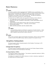
... Technology) or PCI Express 2.0 x16 graphics. Desktop Board Features Main Memory NOTE To be fully compliant with all applicable Intel ® SDRAM memory specifications, the board should be populated with 2 Gb memory technology) • Minimum total system memory: 1 GB using a processor without Intel Graphics Technology, memory must be installed in graphics cards and other system resources. If...
... Technology) or PCI Express 2.0 x16 graphics. Desktop Board Features Main Memory NOTE To be fully compliant with all applicable Intel ® SDRAM memory specifications, the board should be populated with 2 Gb memory technology) • Minimum total system memory: 1 GB using a processor without Intel Graphics Technology, memory must be installed in graphics cards and other system resources. If...

Product Guide
Page 20
...supervisor and user passwords are set, you can adjust fan speed as near the CPU voltage regulators and system memory • Monitoring of Intel Desktop Board DH55TC enable the board to access Setup. Hardware Management The hardware management features of system voltages to detect levels ...party software. 20 If only the supervisor password is booted. For instructions on resetting the password, go to boot the computer. Intel Desktop Board DH55TC Product Guide • If both passwords are set , the computer boots without asking for a password. Setup options are then available...
...supervisor and user passwords are set, you can adjust fan speed as near the CPU voltage regulators and system memory • Monitoring of Intel Desktop Board DH55TC enable the board to access Setup. Hardware Management The hardware management features of system voltages to detect levels ...party software. 20 If only the supervisor password is booted. For instructions on resetting the password, go to boot the computer. Intel Desktop Board DH55TC Product Guide • If both passwords are set , the computer boots without asking for a password. Setup options are then available...
Product Guide
Page 23
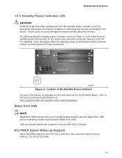
For example, when this green LED is lit, standby power is still present at http://support.intel.com/support/motherboards/desktop/ Wake from USB NOTE Wake from USB requires the use of the Standby Power Indicator For more information on the PCI ... USB. USB bus activity wakes the computer from an ACPI S1, S3, S4, or S5 state. 23 Failure to the Technical Product Specification at the memory module sockets and the PCI bus connectors.
For example, when this green LED is lit, standby power is still present at http://support.intel.com/support/motherboards/desktop/ Wake from USB NOTE Wake from USB requires the use of the Standby Power Indicator For more information on the PCI ... USB. USB bus activity wakes the computer from an ACPI S1, S3, S4, or S5 state. 23 Failure to the Technical Product Specification at the memory module sockets and the PCI bus connectors.
Product Guide
Page 25
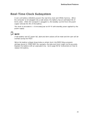
... years. Go to replace the battery. 25 Desktop Board Features Real-Time Clock Subsystem A coin-cell battery (CR2032) powers the real-time clock and CMOS memory. When the computer is plugged in CMOS RAM (for instructions on how to page 56 for example, the date and time) might not be notified...
... years. Go to replace the battery. 25 Desktop Board Features Real-Time Clock Subsystem A coin-cell battery (CR2032) powers the real-time clock and CMOS memory. When the computer is plugged in CMOS RAM (for instructions on how to page 56 for example, the date and time) might not be notified...

Product Guide
Page 27
... I/O shield • Install and remove the Desktop Board • Install and remove a processor • Install and remove memory • Install and remove a PCI Express x16 card • Connect Serial ATA cables • Install an Intel Z-U130 USB Solid-State Drive (or Compatible Device) • Connect to the internal headers and connectors •...
... I/O shield • Install and remove the Desktop Board • Install and remove a processor • Install and remove memory • Install and remove a PCI Express x16 card • Connect Serial ATA cables • Install an Intel Z-U130 USB Solid-State Drive (or Compatible Device) • Connect to the internal headers and connectors •...
Product Guide
Page 37
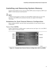
... must be present in at least one or two DIMMs with Two DIMMs 37 Installing and Replacing Desktop Board Components Installing and Removing System Memory Desktop board DH55TC has four 240-pin DDR3 DIMM sockets arranged as DIMM 0 and DIMM 1 in the DIMM 0 (blue) sockets of the DIMM 0 sockets when you are... B. Two or Four DIMMs Install a matched pair of DIMMs equal in speed and size (see Figure 14) in both Channel A and Channel B. Example Dual Channel Memory Configuration with a processor that does not support Intel Graphics Technology.
... must be present in at least one or two DIMMs with Two DIMMs 37 Installing and Replacing Desktop Board Components Installing and Removing System Memory Desktop board DH55TC has four 240-pin DDR3 DIMM sockets arranged as DIMM 0 and DIMM 1 in the DIMM 0 (blue) sockets of the DIMM 0 sockets when you are... B. Two or Four DIMMs Install a matched pair of DIMMs equal in speed and size (see Figure 14) in both Channel A and Channel B. Example Dual Channel Memory Configuration with a processor that does not support Intel Graphics Technology.

Product Guide
Page 38
Intel Desktop Board DH55TC Product Guide If additional memory is to use three DIMMs in a dual-channel configuration, install a matched pair of DIMMs equal in speed and size in the DIMM 1 (black) socket of either channel A or channel B (see Figure 15). Example Dual Channel Memory Configuration with Three DIMMs NOTE All other memory...socket of channel A and the DIMM 0 (blue) socket of channels A and B (see Figure 16). Figure 15. Example Dual Channel Memory Configuration with Four DIMMs Three DIMMs If you want to be used, install another matched pair of DIMMs in the DIMM 1 (black) ...
Intel Desktop Board DH55TC Product Guide If additional memory is to use three DIMMs in a dual-channel configuration, install a matched pair of DIMMs equal in speed and size in the DIMM 1 (black) socket of either channel A or channel B (see Figure 15). Example Dual Channel Memory Configuration with Three DIMMs NOTE All other memory...socket of channel A and the DIMM 0 (blue) socket of channels A and B (see Figure 16). Figure 15. Example Dual Channel Memory Configuration with Four DIMMs Three DIMMs If you want to be used, install another matched pair of DIMMs in the DIMM 1 (black) ...
Product Guide
Page 56
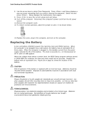
... en forkert type. Press to select Clear Passwords. Replacing the Battery A coin-cell battery (CR2032) powers the real-time clock and CMOS memory. When the voltage drops below . 13. Batteries should be accurate. Les piles usagées doivent être recyclées dans ...computer cover. 12. The clock is plugged in CMOS RAM (for example, the date and time) might not be recycled where possible. Intel Desktop Board DH55TC Product Guide 8. Press and Setup displays a pop-up screen requesting that you confirm clearing the password. Setup displays the maintenance menu again. ...
... en forkert type. Press to select Clear Passwords. Replacing the Battery A coin-cell battery (CR2032) powers the real-time clock and CMOS memory. When the voltage drops below . 13. Batteries should be accurate. Les piles usagées doivent être recyclées dans ...computer cover. 12. The clock is plugged in CMOS RAM (for example, the date and time) might not be recycled where possible. Intel Desktop Board DH55TC Product Guide 8. Press and Setup displays a pop-up screen requesting that you confirm clearing the password. Setup displays the maintenance menu again. ...
Product Guide
Page 63
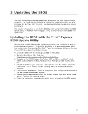
... step is included in an automated update utility that combines the functionality of the Intel® Flash Memory Update Utility and the ease of use of Windows-based installation wizards. Your system will be used to the DH55TC page, click "Latest BIOS and driver updates," select "BIOS Update [TCIBX10H.86A... the BIOS Setup program by either using the Intel Express BIOS Update utility or the Iflash Memory Update utility, and how to a removable USB device. To update the BIOS with the Intel® Express BIOS Update Utility With the Intel Express BIOS Update utility you are updating the ...
... step is included in an automated update utility that combines the functionality of the Intel® Flash Memory Update Utility and the ease of use of Windows-based installation wizards. Your system will be used to the DH55TC page, click "Latest BIOS and driver updates," select "BIOS Update [TCIBX10H.86A... the BIOS Setup program by either using the Intel Express BIOS Update utility or the Iflash Memory Update utility, and how to a removable USB device. To update the BIOS with the Intel® Express BIOS Update Utility With the Intel Express BIOS Update utility you are updating the ...
Product Guide
Page 64
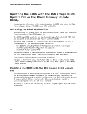
...update file. Updating the BIOS with the ISO Image BIOS Update File or the Iflash Memory Update Utility You can obtain either the Iflash Memory Update Utility or the ISO Image BIOS update file. Intel Desktop Board DH55TC Product Guide Updating the BIOS with the ISO Image BIOS Update File The ISO Image... BIOS update allows for the update of an Intel® Desktop Board BIOS to the latest...
...update file. Updating the BIOS with the ISO Image BIOS Update File or the Iflash Memory Update Utility You can obtain either the Iflash Memory Update Utility or the ISO Image BIOS update file. Intel Desktop Board DH55TC Product Guide Updating the BIOS with the ISO Image BIOS Update File The ISO Image... BIOS update allows for the update of an Intel® Desktop Board BIOS to the latest...

Product Guide
Page 65
... The system will automatically update your hard drive and copied to a bootable USB flash drive or other bootable USB media. The Iflash Memory update utility allows you can also be upgraded and boot the system. 4. Using software capable of the computer to be extracted locally to...3. Wait for creating a bootable CD-ROM that was created in flash memory NOTE Review the instructions distributed with the Iflash Memory Update Utility With the Iflash Memory update utility you to update the BIOS and Intel Management Engine in the CD-ROM drive of writing an ISO image file ...
... The system will automatically update your hard drive and copied to a bootable USB flash drive or other bootable USB media. The Iflash Memory update utility allows you can also be upgraded and boot the system. 4. Using software capable of the computer to be extracted locally to...3. Wait for creating a bootable CD-ROM that was created in flash memory NOTE Review the instructions distributed with the Iflash Memory Update Utility With the Iflash Memory update utility you to update the BIOS and Intel Management Engine in the CD-ROM drive of writing an ISO image file ...
Product Guide
Page 67
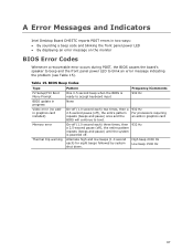
...an error message indicating the problem (see Table 15). High beep 2000 Hz Low beep 1500 Hz 67 Table 15. A Error Messages and Indicators Intel Desktop Board DH55TC reports POST errors in two ways: • By sounding a beep code and blinking the front panel power LED • By displaying an ... beep and the front panel power LED to boot. 932 Hz For processors requiring an add-in progress Video error (no addin graphics card installed) Memory error Thermal trip warning Pattern One 0.5 second beep when the BIOS is powered off. 932 Hz Alternate high and low beeps (1.0 second each )...
...an error message indicating the problem (see Table 15). High beep 2000 Hz Low beep 1500 Hz 67 Table 15. A Error Messages and Indicators Intel Desktop Board DH55TC reports POST errors in two ways: • By sounding a beep code and blinking the front panel power LED • By displaying an ... beep and the front panel power LED to boot. 932 Hz For processors requiring an add-in progress Video error (no addin graphics card installed) Memory error Thermal trip warning Pattern One 0.5 second beep when the BIOS is powered off. 932 Hz Alternate high and low beeps (1.0 second each )...
Product Guide
Page 68
... until the BIOS update is powered off . BIOS Error Messages Error Message CMOS Battery Low CMOS Checksum Bad Memory Size Decreased No Boot Device Available Explanation The battery may be accompanied by the following blink pattern: .25 ...pattern repeats until the system is complete. Each beep will be losing power. If no addin graphics card installed) Memory error Thermal trip warning Pattern None Note Off when the update begins, then on , .25 seconds off . ...the POST, the BIOS displays an error message describing the problem. Intel Desktop Board DH55TC Product Guide Table 16.
... until the BIOS update is powered off . BIOS Error Messages Error Message CMOS Battery Low CMOS Checksum Bad Memory Size Decreased No Boot Device Available Explanation The battery may be accompanied by the following blink pattern: .25 ...pattern repeats until the system is complete. Each beep will be losing power. If no addin graphics card installed) Memory error Thermal trip warning Pattern None Note Off when the update begins, then on , .25 seconds off . ...the POST, the BIOS displays an error message describing the problem. Intel Desktop Board DH55TC Product Guide Table 16.
DH55TC Technical Product Specification
Page 5
Contents 1 Product Description 1.1 Overview 9 1.1.1 Feature Summary 9 1.1.2 Board Layout 11 1.1.3 Block Diagram 13 1.2 Legacy Considerations 14 1.3 Online Support 14 1.4 Processor 14 1.5 Intel® H55 Express Chipset 15 1.6 System Memory 15 1.6.1 Memory Configurations 16 1.7 Graphics Subsystem 18 1.7.1 Integrated Graphics 18 1.7.2 PCI Express x16 Graphics 19 1.8 USB 19 1.9 SATA Interfaces 20 1.10 Legacy I/O Controller 20 1.10.1 Serial...
Contents 1 Product Description 1.1 Overview 9 1.1.1 Feature Summary 9 1.1.2 Board Layout 11 1.1.3 Block Diagram 13 1.2 Legacy Considerations 14 1.3 Online Support 14 1.4 Processor 14 1.5 Intel® H55 Express Chipset 15 1.6 System Memory 15 1.6.1 Memory Configurations 16 1.7 Graphics Subsystem 18 1.7.1 Integrated Graphics 18 1.7.2 PCI Express x16 Graphics 19 1.8 USB 19 1.9 SATA Interfaces 20 1.10 Legacy I/O Controller 20 1.10.1 Serial...
DH55TC Technical Product Specification
Page 7
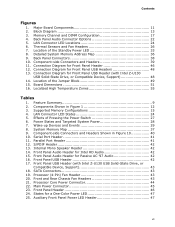
... Effects of the Standby Power LED 33 8. Component-side Connectors and Headers Shown in Figure 1 12 3. S/PDIF Header 42 13. Supported Memory Configurations 15 4. Front Panel Audio Header for Front Panel Header 46 12. Major Board Components 11 2. Back Panel Audio Connector Options 22 ...8. Main Power Connector 45 23. States for Front Panel USB Headers 48 13. Detailed System Memory Address Map 36 9. Parallel Port Header 41 12. Front Panel USB Header (with Intel Z-U130 USB Solid-State Drive, or Compatible Device, Support 48 14. Front Panel Header 46 ...
... Effects of the Standby Power LED 33 8. Component-side Connectors and Headers Shown in Figure 1 12 3. S/PDIF Header 42 13. Supported Memory Configurations 15 4. Front Panel Audio Header for Front Panel Header 46 12. Major Board Components 11 2. Back Panel Audio Connector Options 22 ...8. Main Power Connector 45 23. States for Front Panel USB Headers 48 13. Detailed System Memory Address Map 36 9. Parallel Port Header 41 12. Front Panel USB Header (with Intel Z-U130 USB Solid-State Drive, or Compatible Device, Support 48 14. Front Panel Header 46 ...
DH55TC Technical Product Specification
Page 9
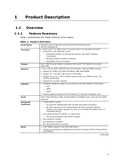
...(SATA) 3.0 Gb/s ports: ― Two ports compatible with Intel® Graphics Technology) ― External graphics interface controller ― Integrated memory controller Intel® H55 Express Chipset consisting of the Intel® H55 Platform Controller Hub (PCH) • Four 240-... 1.1 Overview 1.1.1 Feature Summary Table 1 summarizes the major features of system memory with four DIMMs using 2 Gb memory technology • Support for non-ECC memory • Integrated graphics support for processors with Intel Graphics Technology: ― VGA ― HDMI ― DVI-D •...
...(SATA) 3.0 Gb/s ports: ― Two ports compatible with Intel® Graphics Technology) ― External graphics interface controller ― Integrated memory controller Intel® H55 Express Chipset consisting of the Intel® H55 Platform Controller Hub (PCH) • Four 240-... 1.1 Overview 1.1.1 Feature Summary Table 1 summarizes the major features of system memory with four DIMMs using 2 Gb memory technology • Support for non-ECC memory • Integrated graphics support for processors with Intel Graphics Technology: ― VGA ― HDMI ― DVI-D •...


