
Product Guide
Page 6
Intel Desktop Board DH55TC Product Guide 2 Installing and Replacing Desktop Board Components Before You Begin 27 ... a PCI Express x16 Graphics Card 41 Removing a PCI Express x16 Graphics Card 42 Connecting Serial ATA (SATA) Cables 44 Installing an Intel® Z-U130 USB Solid-State Drive (or Compatible Device 45 Connecting to the Internal Headers 46 Front ... Configuration Jumper 54 Clearing Passwords 55 Replacing the Battery 56 3 Updating the BIOS Updating the BIOS with the Intel® Express BIOS Update Utility 63 Updating the BIOS with the ISO Image BIOS Update File or the Iflash...
Intel Desktop Board DH55TC Product Guide 2 Installing and Replacing Desktop Board Components Before You Begin 27 ... a PCI Express x16 Graphics Card 41 Removing a PCI Express x16 Graphics Card 42 Connecting Serial ATA (SATA) Cables 44 Installing an Intel® Z-U130 USB Solid-State Drive (or Compatible Device 45 Connecting to the Internal Headers 46 Front ... Configuration Jumper 54 Clearing Passwords 55 Replacing the Battery 56 3 Updating the BIOS Updating the BIOS with the Intel® Express BIOS Update Utility 63 Updating the BIOS with the ISO Image BIOS Update File or the Iflash...
Product Guide
Page 10
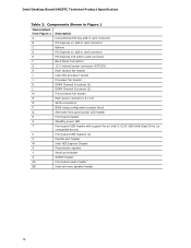
... • Six Serial ATA (SATA) 3.0 Gb/s ports, two ports compatible with eSATA adapters • One serial port header • One parallel port header • One PS/2 back panel connector Intel® 82578DC Gigabit (10/100...ports are implemented with stacked back panel connectors ― Six ports are implemented with integrated status LEDs • Intel® BIOS resident in an SPI Flash device • Support for Advanced Configuration and Power Interface (ACPI), ... • Support for Platform Environmental Control Interface (PECI) 10 Intel Desktop Board DH55TC Product Guide Table 1.
... • Six Serial ATA (SATA) 3.0 Gb/s ports, two ports compatible with eSATA adapters • One serial port header • One parallel port header • One PS/2 back panel connector Intel® 82578DC Gigabit (10/100...ports are implemented with stacked back panel connectors ― Six ports are implemented with integrated status LEDs • Intel® BIOS resident in an SPI Flash device • Support for Advanced Configuration and Power Interface (ACPI), ... • Support for Platform Environmental Control Interface (PECI) 10 Intel Desktop Board DH55TC Product Guide Table 1.
Product Guide
Page 14
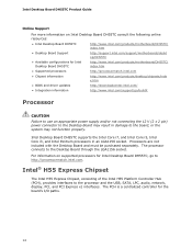
...to the processor and the USB, SATA, LPC, audio, network, display, PCI, and PCI Express x1 interfaces. Intel® H55 Express Chipset The Intel H55 Express Chipset, consisting of the Intel H55 Platform Controller Hub (PCH), ...Intel Desktop Board DH55TC consult the following online resources: • Intel Desktop Board DH55TC http://www.intel.com/products/motherboard/DH55TC/ index.htm • Desktop Board Support http://support.intel.com/support/motherboards/deskt op/DH55TC • Available configurations for Intel Desktop Board DH55TC http://www.intel.com/products/motherboard/DH55TC...
...to the processor and the USB, SATA, LPC, audio, network, display, PCI, and PCI Express x1 interfaces. Intel® H55 Express Chipset The Intel H55 Express Chipset, consisting of the Intel H55 Platform Controller Hub (PCH), ...Intel Desktop Board DH55TC consult the following online resources: • Intel Desktop Board DH55TC http://www.intel.com/products/motherboard/DH55TC/ index.htm • Desktop Board Support http://support.intel.com/support/motherboards/deskt op/DH55TC • Available configurations for Intel Desktop Board DH55TC http://www.intel.com/products/motherboard/DH55TC...
Product Guide
Page 18
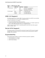
... internal SATA connectors through the PCH, four for internal storage (black connectors) and two for internal as well as follows: • Six ports via stacked back panel connectors • Six front panel ports via three dual-port internal headers; Expandability Intel Desktop Board DH55TC provides ...State Drive (or compatible device) USB 2.0 support requires both an operating system and drivers that allow the use of EHCI-compatible drivers. Intel Desktop Board DH55TC Product Guide Table 3. LAN Connector LEDs LED A (Link/Activity) B (Link Speed) LED Color Green N/A Green Yellow LED State ...
... internal SATA connectors through the PCH, four for internal storage (black connectors) and two for internal as well as follows: • Six ports via stacked back panel connectors • Six front panel ports via three dual-port internal headers; Expandability Intel Desktop Board DH55TC provides ...State Drive (or compatible device) USB 2.0 support requires both an operating system and drivers that allow the use of EHCI-compatible drivers. Intel Desktop Board DH55TC Product Guide Table 3. LAN Connector LEDs LED A (Link/Activity) B (Link Speed) LED Color Green N/A Green Yellow LED State ...
Product Guide
Page 19
... in Chapter 3 starting on page 63. BIOS The BIOS provides the Power-On Self-Test (POST), the BIOS Setup program, and the PCI Express and SATA auto-configuration utilities.
... in Chapter 3 starting on page 63. BIOS The BIOS provides the Power-On Self-Test (POST), the BIOS Setup program, and the PCI Express and SATA auto-configuration utilities.

Product Guide
Page 44
Attach one end of the SATA connectors on page 27. 2. Connecting a Serial ATA Cable 44 Intel Desktop Board DH55TC Product Guide Connecting Serial ATA (SATA) Cables SATA cables support the Serial ATA protocol. Each cable can be used to the SATA drive (Figure 21, B). For correct cable function: 1. Figure 21. Observe the precautions in "Before You Begin" on the board (Figure 21, A) and attach the other end of the cable to connect one of the SATA cable to one internal SATA drive to the Desktop Board.
Attach one end of the SATA connectors on page 27. 2. Connecting a Serial ATA Cable 44 Intel Desktop Board DH55TC Product Guide Connecting Serial ATA (SATA) Cables SATA cables support the Serial ATA protocol. Each cable can be used to the SATA drive (Figure 21, B). For correct cable function: 1. Figure 21. Observe the precautions in "Before You Begin" on the board (Figure 21, A) and attach the other end of the cable to connect one of the SATA cable to one internal SATA drive to the Desktop Board.
DH55TC Technical Product Specification
Page 5
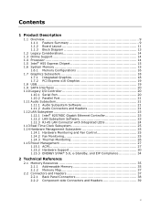
... Layout 11 1.1.3 Block Diagram 13 1.2 Legacy Considerations 14 1.3 Online Support 14 1.4 Processor 14 1.5 Intel® H55 Express Chipset 15 1.6 System Memory 15 1.6.1 Memory Configurations 16 1.7 Graphics Subsystem 18 1.7.1 Integrated Graphics 18 1.7.2 PCI Express x16 Graphics 19 1.8 USB 19 1.9 SATA Interfaces 20 1.10 Legacy I/O Controller 20 1.10.1 Serial Port 20 1.10.2 Parallel Port...
... Layout 11 1.1.3 Block Diagram 13 1.2 Legacy Considerations 14 1.3 Online Support 14 1.4 Processor 14 1.5 Intel® H55 Express Chipset 15 1.6 System Memory 15 1.6.1 Memory Configurations 16 1.7 Graphics Subsystem 18 1.7.1 Integrated Graphics 18 1.7.2 PCI Express x16 Graphics 19 1.8 USB 19 1.9 SATA Interfaces 20 1.10 Legacy I/O Controller 20 1.10.1 Serial Port 20 1.10.2 Parallel Port...
DH55TC Technical Product Specification
Page 7
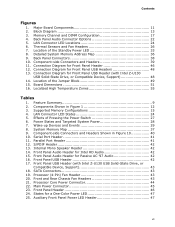
... Zones 55 Tables 1. S/PDIF Header 42 13. Front Panel USB Header 42 17. SATA Connectors 43 19. Processor (4-Pin) Fan Header 43 20. States for Front Panel USB Header (with Intel Z-U130 USB Solid-State Drive, or Compatible Device, Support 43 18. Component-side Connectors... Components 11 2. Supported Memory Configurations 15 4. Wake-up Devices and Events 29 8. System Memory Map 37 9. Front Panel USB Header (with Intel Z-U130 USB Solid-State Drive, or Compatible Device, Support 48 14. Back Panel Connectors 38 10. Front and Rear Chassis Fan Headers 43 21...
... Zones 55 Tables 1. S/PDIF Header 42 13. Front Panel USB Header 42 17. SATA Connectors 43 19. Processor (4-Pin) Fan Header 43 20. States for Front Panel USB Header (with Intel Z-U130 USB Solid-State Drive, or Compatible Device, Support 43 18. Component-side Connectors... Components 11 2. Supported Memory Configurations 15 4. Wake-up Devices and Events 29 8. System Memory Map 37 9. Front Panel USB Header (with Intel Z-U130 USB Solid-State Drive, or Compatible Device, Support 48 14. Back Panel Connectors 38 10. Front and Rear Chassis Fan Headers 43 21...
DH55TC Technical Product Specification
Page 9
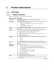
...or compatible device) • Six internal Serial ATA (SATA) 3.0 Gb/s ports: ― Two ports compatible with eSATA dongles • One serial port header • One parallel port header • One back panel PS/2 connector • Intel® BIOS resident in the SPI Flash device &#...• Twelve USB 2.0 ports: ― Six ports are implemented with stacked back panel connectors ― Six front panel ports are implemented with Intel Graphics Technology: ― VGA ― HDMI ― DVI-D • Discrete graphics support for Advanced Configuration and Power Interface (ACPI), Plug...
...or compatible device) • Six internal Serial ATA (SATA) 3.0 Gb/s ports: ― Two ports compatible with eSATA dongles • One serial port header • One parallel port header • One back panel PS/2 connector • Intel® BIOS resident in the SPI Flash device &#...• Twelve USB 2.0 ports: ― Six ports are implemented with stacked back panel connectors ― Six front panel ports are implemented with Intel Graphics Technology: ― VGA ― HDMI ― DVI-D • Discrete graphics support for Advanced Configuration and Power Interface (ACPI), Plug...
DH55TC Technical Product Specification
Page 12
... fan header K DIMM Channel A sockets (2) L DIMM Channel B sockets (2) M Front chassis fan header N Main power connector (2 x 12) O SATA connectors P BIOS setup configuration jumper block Q Alternate front panel power LED header R Front panel header S Standby power LED T Front panel USB header with... support for an Intel Z-U130 USB Solid-State Drive (or compatible device) U Front panel USB headers (2) V Parallel port header W Intel H55 Express Chipset X Piezoelectric speaker Y Serial port header Z S/PDIF header...
... fan header K DIMM Channel A sockets (2) L DIMM Channel B sockets (2) M Front chassis fan header N Main power connector (2 x 12) O SATA connectors P BIOS setup configuration jumper block Q Alternate front panel power LED header R Front panel header S Standby power LED T Front panel USB header with... support for an Intel Z-U130 USB Solid-State Drive (or compatible device) U Front panel USB headers (2) V Parallel port header W Intel H55 Express Chipset X Piezoelectric speaker Y Serial port header Z S/PDIF header...

DH55TC Technical Product Specification
Page 15
... two rows of SDRAM) and "SS" refers to single-sided memory modules (containing one row of the Intel H55 Platform Controller Hub (PCH) provides interfaces to the processor and the USB, SATA, LPC, audio, network, display, Conventional PCI, and PCI Express x1 interfaces. This allows the BIOS to... read the SPD data and program the chipset to http://www.intel.com/products/desktop/chipsets/index.htm Chapter 2 1.6 System Memory...
... two rows of SDRAM) and "SS" refers to single-sided memory modules (containing one row of the Intel H55 Platform Controller Hub (PCH) provides interfaces to the processor and the USB, SATA, LPC, audio, network, display, Conventional PCI, and PCI Express x1 interfaces. This allows the BIOS to... read the SPD data and program the chipset to http://www.intel.com/products/desktop/chipsets/index.htm Chapter 2 1.6 System Memory...
DH55TC Technical Product Specification
Page 20
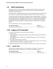
... connectivity (red connectors). For information about The location of the SATA connectors Refer to Figure 10, page 39 20 The SATA controller can operate in both legacy and native modes. Intel Desktop Board DH55TC Technical Product Specification 1.9 SATA Interfaces The board provides six internal SATA connectors through the PCH, four for internal storage (black connectors) and...
... connectivity (red connectors). For information about The location of the SATA connectors Refer to Figure 10, page 39 20 The SATA controller can operate in both legacy and native modes. Intel Desktop Board DH55TC Technical Product Specification 1.9 SATA Interfaces The board provides six internal SATA connectors through the PCH, four for internal storage (black connectors) and...
DH55TC Technical Product Specification
Page 40
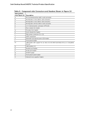
Intel Desktop Board DH55TC Technical Product Specification Table 9. Component-side Connectors and Headers Shown in Figure 10 Item/callout from Figure 10 A B C D E F G H I J K L Description PCI Conventional bus add-in card ... connector (ATX12V) Rear chassis fan header Processor fan header Front chassis fan header Main power connector (2 x 12) SATA connectors Alternate front panel power LED header Front panel header M USB header with support for an Intel Z-U130 USB Solid-State Drive (or compatible device) N USB headers (2) O Parallel port header P Serial port header Q S/PDIF...
Intel Desktop Board DH55TC Technical Product Specification Table 9. Component-side Connectors and Headers Shown in Figure 10 Item/callout from Figure 10 A B C D E F G H I J K L Description PCI Conventional bus add-in card ... connector (ATX12V) Rear chassis fan header Processor fan header Front chassis fan header Main power connector (2 x 12) SATA connectors Alternate front panel power LED header Front panel header M USB header with support for an Intel Z-U130 USB Solid-State Drive (or compatible device) N USB headers (2) O Parallel port header P Serial port header Q S/PDIF...
DH55TC Technical Product Specification
Page 43
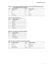
... Fan Headers Pin 4-Wire Support Pin 3-Wire Support 1 Ground 3 Ground 2 +12 V 2 FAN_POWER 3 FAN_TACH 1 FAN_TACH 4 FAN_CONTROL N/A N/A 43 Technical Reference Table 17. Front Panel USB Header (with Intel Z-U130 USB Solid-State Drive, or Compatible Device, Support) Pin Signal Name Pin Signal Name 1 +5 VDC 3 D− 5 D+ 7 Ground 9 KEY (no pin) 2 +5 VDC 4 D− 6 D+ 8 Ground 10...
... Fan Headers Pin 4-Wire Support Pin 3-Wire Support 1 Ground 3 Ground 2 +12 V 2 FAN_POWER 3 FAN_TACH 1 FAN_TACH 4 FAN_CONTROL N/A N/A 43 Technical Reference Table 17. Front Panel USB Header (with Intel Z-U130 USB Solid-State Drive, or Compatible Device, Support) Pin Signal Name Pin Signal Name 1 +5 VDC 3 D− 5 D+ 7 Ground 9 KEY (no pin) 2 +5 VDC 4 D− 6 D+ 8 Ground 10...

DH55TC Technical Product Specification
Page 46
...Out Description Hard Drive Activity LED 1 HD_PWR Out Hard disk LED pull-up to an onboard SATA connector, or the use of an Intel Z-U130 Solid-State Drive (or compatible device). 46 Proper LED function requires a SATA hard drive or optical drive connected to +5 V 3 HDA# Out Hard disk active LED ... storage device. Connection Diagram for the front panel header. Table 23 lists the signal names of the front panel header. Intel Desktop Board DH55TC Technical Product Specification 2.2.2.4 Front Panel Header This section describes the functions of the front panel header.
...Out Description Hard Drive Activity LED 1 HD_PWR Out Hard disk LED pull-up to an onboard SATA connector, or the use of an Intel Z-U130 Solid-State Drive (or compatible device). 46 Proper LED function requires a SATA hard drive or optical drive connected to +5 V 3 HDA# Out Hard disk active LED ... storage device. Connection Diagram for the front panel header. Table 23 lists the signal names of the front panel header. Intel Desktop Board DH55TC Technical Product Specification 2.2.2.4 Front Panel Header This section describes the functions of the front panel header.
DH55TC Technical Product Specification
Page 63
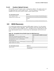
... BIOS Recovery Media Type Can be used for BIOS recovery. Optical drive connected to the SATA interface Yes USB removable drive (a USB Flash Drive, for BIOS recovery? The Intel Integrator's Toolkit that can be damaged. Table 34. This splash screen can and cannot ...bio file at the root level. For information about BIOS recovery Refer to http://developer.intel.com/design/motherbd/software/itk/ http://developer.intel.com/products/motherboard/DH55TC/ tools.htm and http://developer.intel.com/design/motherbd/software.htm 3.5 BIOS Recovery It is unlikely that anything will interrupt...
... BIOS Recovery Media Type Can be used for BIOS recovery. Optical drive connected to the SATA interface Yes USB removable drive (a USB Flash Drive, for BIOS recovery? The Intel Integrator's Toolkit that can be damaged. Table 34. This splash screen can and cannot ...bio file at the root level. For information about BIOS recovery Refer to http://developer.intel.com/design/motherbd/software/itk/ http://developer.intel.com/products/motherboard/DH55TC/ tools.htm and http://developer.intel.com/design/motherbd/software.htm 3.5 BIOS Recovery It is unlikely that anything will interrupt...
DH55TC Technical Product Specification
Page 70
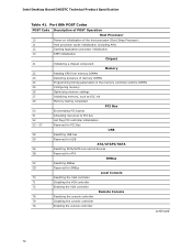
Intel Desktop Board DH55TC Technical Product Specification Table 41. Port 80h POST Codes POST Code Description of POST Operation Host Processor 10 Power-on initialization of the host processor (... 52 Hot Plug PCI controller initialization 53 - 57 Reserved for PCI Bus USB 58 Resetting USB bus 59 Reserved for USB ATA/ATAPI/SATA 5A Resetting PATA/SATA bus and all devices 5B Reserved for ATA SMBus 5C Resetting SMBus 5D Reserved for SMBus Local Console 70 Resetting the VGA controller 71...
Intel Desktop Board DH55TC Technical Product Specification Table 41. Port 80h POST Codes POST Code Description of POST Operation Host Processor 10 Power-on initialization of the host processor (... 52 Hot Plug PCI controller initialization 53 - 57 Reserved for PCI Bus USB 58 Resetting USB bus 59 Reserved for USB ATA/ATAPI/SATA 5A Resetting PATA/SATA bus and all devices 5B Reserved for ATA SMBus 5C Resetting SMBus 5D Reserved for SMBus Local Console 70 Resetting the VGA controller 71...
DH55TC Technical Product Specification
Page 73
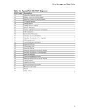
... the keyboard 90 Resetting keyboard 94 Clearing keyboard input buffer 95 Keyboard Self Test EB Calling Video BIOS 58 Resetting USB bus 5A Resetting PATA/SATA bus and all devices 92 Detecting the presence of the keyboard 90 Resetting keyboard 94 Clearing keyboard input buffer 5A Resetting PATA...
... the keyboard 90 Resetting keyboard 94 Clearing keyboard input buffer 95 Keyboard Self Test EB Calling Video BIOS 58 Resetting USB bus 5A Resetting PATA/SATA bus and all devices 92 Detecting the presence of the keyboard 90 Resetting keyboard 94 Clearing keyboard input buffer 5A Resetting PATA...
Simplified Chinese Product Guide
Page 14
.../support/go/buildit 处理器 12 V(2 x 2 DH55TC LGA1156 i7 i5 i3 LGA1156 DH55TC http://processormatch.intel.com。 英特尔® H55 Express 芯片组 英特尔 H55 Express Intel H55 Platform Controller Hub H55 PCH USB、SATA、LPC PCI 以及 PCI Express x1 PCH 是主...
.../support/go/buildit 处理器 12 V(2 x 2 DH55TC LGA1156 i7 i5 i3 LGA1156 DH55TC http://processormatch.intel.com。 英特尔® H55 Express 芯片组 英特尔 H55 Express Intel H55 Platform Controller Hub H55 PCH USB、SATA、LPC PCI 以及 PCI Express x1 PCH 是主...


