

Product Guide
Page 5
Contents 1 Desktop Board Features Supported Operating Systems 11 Desktop Board Components 12 Processor ...14 Intel® H55 Express Chipset 14 Main Memory...15 Graphics Subsystem 15 Integrated Graphics 15 Analog Display (VGA 15 High-Definition Multimedia Interface* (HDMI 16 Digital Visual ... 17 USB 2.0 Support 18 Serial ATA Support 18 Expandability...18 Legacy I/O ...19 BIOS ...19 Serial ATA Auto Configuration 19 PCI*/PCI Express Auto Configuration 19 Security Passwords 19 Hardware Management 20 Hardware Monitoring and Fan Speed Control 20 Fan Monitoring 20 Power Management 21 ...
Contents 1 Desktop Board Features Supported Operating Systems 11 Desktop Board Components 12 Processor ...14 Intel® H55 Express Chipset 14 Main Memory...15 Graphics Subsystem 15 Integrated Graphics 15 Analog Display (VGA 15 High-Definition Multimedia Interface* (HDMI 16 Digital Visual ... 17 USB 2.0 Support 18 Serial ATA Support 18 Expandability...18 Legacy I/O ...19 BIOS ...19 Serial ATA Auto Configuration 19 PCI*/PCI Express Auto Configuration 19 Security Passwords 19 Hardware Management 20 Hardware Monitoring and Fan Speed Control 20 Fan Monitoring 20 Power Management 21 ...
Product Guide
Page 6
Intel Desktop Board DH55TC Product Guide 2 Installing and Replacing Desktop Board Components Before You Begin 27 Installation Precautions 28 Prevent Power Supply Overload 28 Observe Safety and Regulatory Requirements ... Dual Channel Memory Configuration 37 Two or Four DIMMs 37 Three DIMMs 38 Installing DIMMs 39 Removing DIMMs 41 Installing and Removing PCI Express x16 Graphics Cards 41 Installing a PCI Express x16 Graphics Card 41 Removing a PCI Express x16 Graphics Card 42 Connecting Serial ATA (SATA) Cables 44 Installing an Intel® Z-U130...
Intel Desktop Board DH55TC Product Guide 2 Installing and Replacing Desktop Board Components Before You Begin 27 Installation Precautions 28 Prevent Power Supply Overload 28 Observe Safety and Regulatory Requirements ... Dual Channel Memory Configuration 37 Two or Four DIMMs 37 Three DIMMs 38 Installing DIMMs 39 Removing DIMMs 41 Installing and Removing PCI Express x16 Graphics Cards 41 Installing a PCI Express x16 Graphics Card 41 Removing a PCI Express x16 Graphics Card 42 Connecting Serial ATA (SATA) Cables 44 Installing an Intel® Z-U130...
Product Guide
Page 7
... Sink Power Cable to the Processor Fan Header 36 14. Example Dual Channel Memory Configuration with Three DIMMs 38 17. Connecting a Serial ATA Cable 44 22. Intel Desktop Board DH55TC China RoHS Material Self Declaration Table 77 vii Example Dual Channel Memory Configuration with Four DIMMs 38 16. Installing the I/O Shield 29 5. Lift the Load Plate...
... Sink Power Cable to the Processor Fan Header 36 14. Example Dual Channel Memory Configuration with Three DIMMs 38 17. Connecting a Serial ATA Cable 44 22. Intel Desktop Board DH55TC China RoHS Material Self Declaration Table 77 vii Example Dual Channel Memory Configuration with Four DIMMs 38 16. Installing the I/O Shield 29 5. Lift the Load Plate...
Product Guide
Page 15
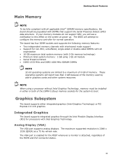
... DIMMs NOTE 32-bit operating systems are limited to configure the memory controller for the POST whenever a monitor is enabled for normal operation. The VGA port is attached, regardless of memory. Desktop Board Features Main Memory NOTE To be fully compliant with all applicable Intel ® SDRAM memory specifications, the board should be installed in graphics...
... DIMMs NOTE 32-bit operating systems are limited to configure the memory controller for the POST whenever a monitor is enabled for normal operation. The VGA port is attached, regardless of memory. Desktop Board Features Main Memory NOTE To be fully compliant with all applicable Intel ® SDRAM memory specifications, the board should be installed in graphics...

Product Guide
Page 27
...an antistatic wrist strap and attaching it to record information about your computer, such as model, serial numbers, installed options, and configuration information. • Electrostatic discharge (ESD) can damage components. Disconnect the computer from its power source and from any telecommunications ...remove the Desktop Board • Install and remove a processor • Install and remove memory • Install and remove a PCI Express x16 card • Connect Serial ATA cables • Install an Intel Z-U130 USB Solid-State Drive (or Compatible Device) • Connect to the internal ...
...an antistatic wrist strap and attaching it to record information about your computer, such as model, serial numbers, installed options, and configuration information. • Electrostatic discharge (ESD) can damage components. Disconnect the computer from its power source and from any telecommunications ...remove the Desktop Board • Install and remove a processor • Install and remove memory • Install and remove a PCI Express x16 card • Connect Serial ATA cables • Install an Intel Z-U130 USB Solid-State Drive (or Compatible Device) • Connect to the internal ...
Product Guide
Page 37
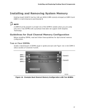
...Memory Configuration with a processor that does not support Intel Graphics Technology. Two or Four DIMMs Install a matched pair of DIMMs equal in speed and size (see Figure 14) in both Channel A and Channel B. Installing and Replacing Desktop Board Components Installing and Removing System Memory Desktop board DH55TC... has four 240-pin DDR3 DIMM sockets arranged as DIMM 0 and DIMM 1 in the DIMM 0 (blue) sockets of channels A and B. Guidelines for Dual Channel Memory Configuration Before installing DIMMs, read and ...
...Memory Configuration with a processor that does not support Intel Graphics Technology. Two or Four DIMMs Install a matched pair of DIMMs equal in speed and size (see Figure 14) in both Channel A and Channel B. Installing and Replacing Desktop Board Components Installing and Removing System Memory Desktop board DH55TC... has four 240-pin DDR3 DIMM sockets arranged as DIMM 0 and DIMM 1 in the DIMM 0 (blue) sockets of channels A and B. Guidelines for Dual Channel Memory Configuration Before installing DIMMs, read and ...

Product Guide
Page 38
... Channel Memory Configuration with Three DIMMs NOTE All other memory configurations will result in single channel memory operation. 38 Figure 15. Example Dual Channel Memory Configuration with Four DIMMs Three DIMMs If you want to be used, install another matched pair of DIMMs in the DIMM 1 (black) sockets of channels A and B (see Figure 16). Intel Desktop Board DH55TC Product...
... Channel Memory Configuration with Three DIMMs NOTE All other memory configurations will result in single channel memory operation. 38 Figure 15. Example Dual Channel Memory Configuration with Four DIMMs Three DIMMs If you want to be used, install another matched pair of DIMMs in the DIMM 1 (black) sockets of channels A and B (see Figure 16). Intel Desktop Board DH55TC Product...
Product Guide
Page 64
...Board BIOS to the latest production release regardless of the operating system installed on the Intel World Wide Web site at: http://support.intel.com/support/motherboards/desktop Navigate to the DH55TC page, click "Latest BIOS and driver updates," select "BIOS Update [TCIBX10H.86A...update file contains: • New BIOS file (including the Intel® Management Engine Firmware Image) • Intel® Integrator Toolkit Configuration File (optional) • Intel Flash Memory Update Utility You can obtain either the Iflash Memory Update Utility or the ISO Image BIOS update file. The ISO...
...Board BIOS to the latest production release regardless of the operating system installed on the Intel World Wide Web site at: http://support.intel.com/support/motherboards/desktop Navigate to the DH55TC page, click "Latest BIOS and driver updates," select "BIOS Update [TCIBX10H.86A...update file contains: • New BIOS file (including the Intel® Management Engine Firmware Image) • Intel® Integrator Toolkit Configuration File (optional) • Intel Flash Memory Update Utility You can obtain either the Iflash Memory Update Utility or the ISO Image BIOS update file. The ISO...
DH55TC Technical Product Specification
Page 5
Contents 1 Product Description 1.1 Overview 9 1.1.1 Feature Summary 9 1.1.2 Board Layout 11 1.1.3 Block Diagram 13 1.2 Legacy Considerations 14 1.3 Online Support 14 1.4 Processor 14 1.5 Intel® H55 Express Chipset 15 1.6 System Memory 15 1.6.1 Memory Configurations 16 1.7 Graphics Subsystem 18 1.7.1 Integrated Graphics 18 1.7.2 PCI Express x16 Graphics 19 1.8 USB 19 1.9 SATA Interfaces 20 1.10 Legacy I/O Controller 20 1.10.1 Serial Port...
Contents 1 Product Description 1.1 Overview 9 1.1.1 Feature Summary 9 1.1.2 Board Layout 11 1.1.3 Block Diagram 13 1.2 Legacy Considerations 14 1.3 Online Support 14 1.4 Processor 14 1.5 Intel® H55 Express Chipset 15 1.6 System Memory 15 1.6.1 Memory Configurations 16 1.7 Graphics Subsystem 18 1.7.1 Integrated Graphics 18 1.7.2 PCI Express x16 Graphics 19 1.8 USB 19 1.9 SATA Interfaces 20 1.10 Legacy I/O Controller 20 1.10.1 Serial Port...
DH55TC Technical Product Specification
Page 7
...Summary 9 2. Components Shown in Figure 10 40 10. Supported Memory Configurations 15 4. Wake-up Devices and Events 29 8. Processor Core Power Connector 44 22. Contents Figures 1. Major Board Components 11 2. Detailed System Memory Address Map 36 9. Connection Diagram for Front Panel Header 46...Mono Speaker Header 42 14. Front Panel Audio Header for Intel HD Audio 42 15. Front and Rear Chassis Fan Headers 43 21. Memory Channel and DIMM Configuration 17 4. Component-side Connectors and Headers 39 11. System Memory Map 37 9. Main Power Connector 45 23.
...Summary 9 2. Components Shown in Figure 10 40 10. Supported Memory Configurations 15 4. Wake-up Devices and Events 29 8. Processor Core Power Connector 44 22. Contents Figures 1. Major Board Components 11 2. Detailed System Memory Address Map 36 9. Connection Diagram for Front Panel Header 46...Mono Speaker Header 42 14. Front Panel Audio Header for Intel HD Audio 42 15. Front and Rear Chassis Fan Headers 43 21. Memory Channel and DIMM Configuration 17 4. Component-side Connectors and Headers 39 11. System Memory Map 37 9. Main Power Connector 45 23.
DH55TC Technical Product Specification
Page 9
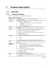
...1 Product Description 1.1 Overview 1.1.1 Feature Summary Table 1 summarizes the major features of system memory with four DIMMs using 2 Gb memory technology • Support for non-ECC memory • Integrated graphics support for processors with Intel Graphics Technology: ― VGA ― HDMI ― DVI-D • Discrete graphics ... port header • One parallel port header • One back panel PS/2 connector • Intel® BIOS resident in the SPI Flash device • Support for Advanced Configuration and Power Interface (ACPI), Plug and Play, and SMBIOS continued 9
...1 Product Description 1.1 Overview 1.1.1 Feature Summary Table 1 summarizes the major features of system memory with four DIMMs using 2 Gb memory technology • Support for non-ECC memory • Integrated graphics support for processors with Intel Graphics Technology: ― VGA ― HDMI ― DVI-D • Discrete graphics ... port header • One parallel port header • One back panel PS/2 connector • Intel® BIOS resident in the SPI Flash device • Support for Advanced Configuration and Power Interface (ACPI), Plug and Play, and SMBIOS continued 9
DH55TC Technical Product Specification
Page 14
... up-to support the Intel Core i7, Intel Core i5, Intel Core i3, and Intel Pentium processors in the future. Intel Desktop Board DH55TC Desktop Board Support Available configurations for this World Wide Web site: http://www.intel.com/products/motherboard/DH55TC/index.htm http://www.intel.com/support/motherboards/desktop http://www.intel.com/products/motherboard/DH55TC/index.htm http://processormatch...
... up-to support the Intel Core i7, Intel Core i5, Intel Core i3, and Intel Pentium processors in the future. Intel Desktop Board DH55TC Desktop Board Support Available configurations for this World Wide Web site: http://www.intel.com/products/motherboard/DH55TC/index.htm http://www.intel.com/support/motherboards/desktop http://www.intel.com/products/motherboard/DH55TC/index.htm http://processormatch...

DH55TC Technical Product Specification
Page 15
... performance. The PCH is installed, the BIOS will attempt to accurately configure memory settings for the board's I/O paths. Table 3. Product Description 1.5 Intel® H55 Express Chipset The Intel H55 Express Chipset consisting of the Intel H55 Platform Controller Hub (PCH) provides interfaces to single-sided memory modules (containing one row of SDRAM). 15 Refer to http...
... performance. The PCH is installed, the BIOS will attempt to accurately configure memory settings for the board's I/O paths. Table 3. Product Description 1.5 Intel® H55 Express Chipset The Intel H55 Express Chipset consisting of the Intel H55 Platform Controller Hub (PCH) provides interfaces to single-sided memory modules (containing one row of SDRAM). 15 Refer to http...
DH55TC Technical Product Specification
Page 16
.... This mode is installed or the memory capacities are used between channels, the slowest memory timing will be equal. Memory Configuration Examples Refer to the other but the installed memory capacity for each channel must be used when only a single DIMM is equivalent to the other . Intel Desktop Board DH55TC Technical Product Specification For information about ... This...
.... This mode is installed or the memory capacities are used between channels, the slowest memory timing will be equal. Memory Configuration Examples Refer to the other but the installed memory capacity for each channel must be used when only a single DIMM is equivalent to the other . Intel Desktop Board DH55TC Technical Product Specification For information about ... This...

DH55TC Technical Product Specification
Page 17
Memory Channel and DIMM Configuration NOTE When using a processor without Intel Graphics Technology: there must always be memory installed into any or both of the DIMM 0 (blue) memory slots for the system to boot. 17 Figure 3. Product Description Figure 3 illustrates the memory channel and DIMM configuration.
Memory Channel and DIMM Configuration NOTE When using a processor without Intel Graphics Technology: there must always be memory installed into any or both of the DIMM 0 (blue) memory slots for the system to boot. 17 Figure 3. Product Description Figure 3 illustrates the memory channel and DIMM configuration.

DH55TC Technical Product Specification
Page 35
...PCI Conventional bus add-in cards, PCI Express configuration space, BIOS (SPI Flash device), and chipset overhead resides above the 4 GB boundary. 2 Technical Reference 2.1 Memory Resources 2.1.1 Addressable Memory The board utilizes 16 GB of the system memory map. On a system that is no overlap...side bus interrupts (17 MB) • PCI Express configuration space (256 MB) • PCH base address registers PCI Express ports (up to an equivalent sized logical address range located just above the top of system memory installed, it is allocated for other system critical functions....
...PCI Conventional bus add-in cards, PCI Express configuration space, BIOS (SPI Flash device), and chipset overhead resides above the 4 GB boundary. 2 Technical Reference 2.1 Memory Resources 2.1.1 Addressable Memory The board utilizes 16 GB of the system memory map. On a system that is no overlap...side bus interrupts (17 MB) • PCI Express configuration space (256 MB) • PCH base address registers PCI Express ports (up to an equivalent sized logical address range located just above the top of system memory installed, it is allocated for other system critical functions....
DH55TC Technical Product Specification
Page 52
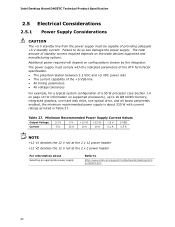
... processor (see Section 1.4 on page 14 for a typical system configuration of providing adequate +5 V standby current. Failure to http://www.intel.com/support/motherboards/desktop/sb/C S-026472.htm 52 Intel Desktop Board DH55TC Technical Product Specification 2.5 Electrical Considerations 2.5.1 Power Supply Considerations CAUTION The... timing parameters • All voltage tolerances For example, for information on supported processors), up to 16 GB DDR3 memory, integrated graphics, one hard disk drive, one optical drive, and all board peripherals enabled, the minimum recommended power...
... processor (see Section 1.4 on page 14 for a typical system configuration of providing adequate +5 V standby current. Failure to http://www.intel.com/support/motherboards/desktop/sb/C S-026472.htm 52 Intel Desktop Board DH55TC Technical Product Specification 2.5 Electrical Considerations 2.5.1 Power Supply Considerations CAUTION The... timing parameters • All voltage tolerances For example, for information on supported processors), up to 16 GB DDR3 memory, integrated graphics, one hard disk drive, one optical drive, and all board peripherals enabled, the minimum recommended power...

DH55TC Technical Product Specification
Page 59
The initial production BIOSs are identified as TCIBX10H.86A. The BIOS Setup program can be used to put the board in configure mode. 59 The SPI Flash contains the BIOS Setup program, POST, LAN EEPROM information, Plug and Play support, and other firmware. Section 2.3 on page ... Boot Exit NOTE The maintenance menu is displayed only when the board is in configure mode. 3 Overview of BIOS Features 3.1 Introduction The board uses an Intel BIOS that is stored in a 64 Mbit (8,192 KB) Serial Peripheral Interface Flash Memory (SPI Flash) device which can be updated using a set of BIOS and a...
The initial production BIOSs are identified as TCIBX10H.86A. The BIOS Setup program can be used to put the board in configure mode. 59 The SPI Flash contains the BIOS Setup program, POST, LAN EEPROM information, Plug and Play support, and other firmware. Section 2.3 on page ... Boot Exit NOTE The maintenance menu is displayed only when the board is in configure mode. 3 Overview of BIOS Features 3.1 Introduction The board uses an Intel BIOS that is stored in a 64 Mbit (8,192 KB) Serial Peripheral Interface Flash Memory (SPI Flash) device which can be updated using a set of BIOS and a...

DH55TC Technical Product Specification
Page 60
...Security Clears passwords and displays processor information Displays processor and memory configuration Configures advanced features available through the chipset Configures Memory and Processor overrides Sets passwords and security features Power Configures power management features Boot Selects boot options Exit Saves ...a field (i.e., date/time) Executes command or selects the submenu Load the default configuration values for menu screens. Intel Desktop Board DH55TC Technical Product Specification Table 32 lists the BIOS Setup program menu features. Table 32. Table 33....
...Security Clears passwords and displays processor information Displays processor and memory configuration Configures advanced features available through the chipset Configures Memory and Processor overrides Sets passwords and security features Power Configures power management features Boot Selects boot options Exit Saves ...a field (i.e., date/time) Executes command or selects the submenu Load the default configuration values for menu screens. Intel Desktop Board DH55TC Technical Product Specification Table 32 lists the BIOS Setup program menu features. Table 32. Table 33....
DH55TC Technical Product Specification
Page 61
...under the Additional Information header under the Main BIOS page. 3.3 Legacy USB Support Legacy USB support enables USB devices to be used to configure the operating system. (Keyboards and mice are not recognized during this period if Legacy USB support was set to Enabled. Legacy USB support... such as the BIOS revision level • Fixed-system data, such as peripherals, serial numbers, and asset tags • Resource data, such as memory size, cache size, and processor speed • Dynamic data, such as follows: 1. Legacy USB support operates as event detection and error logging Non...
...under the Additional Information header under the Main BIOS page. 3.3 Legacy USB Support Legacy USB support enables USB devices to be used to configure the operating system. (Keyboards and mice are not recognized during this period if Legacy USB support was set to Enabled. Legacy USB support... such as the BIOS revision level • Fixed-system data, such as peripherals, serial numbers, and asset tags • Resource data, such as memory size, cache size, and processor speed • Dynamic data, such as follows: 1. Legacy USB support operates as event detection and error logging Non...


