
Product Guide
Page 15
... memory specifications, the board should be installed in graphics cards and other system resources. The BIOS will see a notification to boot. The board has four DIMM sockets and supports the following memory features: • Two independent memory channels with interleaved mode ...Support for processors with DIMMs that support the Serial Presence Detect (SPD) data structure. Integrated Graphics The board supports integrated graphics through the Intel Flexible Display Interface (FDI) for non-ECC, unbuffered, single-sided or double-sided DIMMs with x8 organization • 16 GB maximum ...
... memory specifications, the board should be installed in graphics cards and other system resources. The BIOS will see a notification to boot. The board has four DIMM sockets and supports the following memory features: • Two independent memory channels with interleaved mode ...Support for processors with DIMMs that support the Serial Presence Detect (SPD) data structure. Integrated Graphics The board supports integrated graphics through the Intel Flexible Display Interface (FDI) for non-ECC, unbuffered, single-sided or double-sided DIMMs with x8 organization • 16 GB maximum ...
Product Guide
Page 19
... provides the Power-On Self-Test (POST), the BIOS Setup program, and the PCI Express and SATA auto-configuration utilities. The BIOS can boot the computer. You do not need to run the BIOS Setup program after installing a Serial ATA device. You do not need to run the..., pressing at the password prompt of Setup gives the user restricted access to Setup. 19 The BIOS is set for the BIOS Setup and for booting the computer, with serialized IRQ support for PCI Conventional bus systems • PS/2-style keyboard/mouse interface • Intelligent power management, including a ...
... provides the Power-On Self-Test (POST), the BIOS Setup program, and the PCI Express and SATA auto-configuration utilities. The BIOS can boot the computer. You do not need to run the BIOS Setup program after installing a Serial ATA device. You do not need to run the..., pressing at the password prompt of Setup gives the user restricted access to Setup. 19 The BIOS is set for the BIOS Setup and for booting the computer, with serialized IRQ support for PCI Conventional bus systems • PS/2-style keyboard/mouse interface • Intelligent power management, including a ...

Product Guide
Page 20
... acceptable values • Thermally monitored closed-loop fan control for viewing and changing depending on page 55. Intel Desktop Board DH55TC Product Guide • If both passwords are set, you must enter either password to boot the computer. For instructions on resetting the password, go to Clearing Passwords on whether the supervisor or...
... acceptable values • Thermally monitored closed-loop fan control for viewing and changing depending on page 55. Intel Desktop Board DH55TC Product Guide • If both passwords are set, you must enter either password to boot the computer. For instructions on resetting the password, go to Clearing Passwords on whether the supervisor or...

Product Guide
Page 21
... Power Connectors ATX12V-compliant power supplies can be set by using the Last Power State feature in before power was in the BIOS Setup program's Boot menu. When resuming from serial port Software Support ACPI ACPI gives the operating system direct control over the power management and Plug and Play functions...
... Power Connectors ATX12V-compliant power supplies can be set by using the Last Power State feature in before power was in the BIOS Setup program's Boot menu. When resuming from serial port Software Support ACPI ACPI gives the operating system direct control over the power management and Plug and Play functions...

Product Guide
Page 55
... to the computer. Installing and Replacing Desktop Board Components The three-pin BIOS jumper block enables board configuration to boot. 7. Use this menu to clear passwords. Table 14 shows the jumper settings for booting. Jumper Settings for the BIOS Setup Program Modes Jumper Setting Mode Normal (default) (1-2) Description The BIOS uses the...
... to the computer. Installing and Replacing Desktop Board Components The three-pin BIOS jumper block enables board configuration to boot. 7. Use this menu to clear passwords. Table 14 shows the jumper settings for booting. Jumper Settings for the BIOS Setup Program Modes Jumper Setting Mode Normal (default) (1-2) Description The BIOS uses the...
Product Guide
Page 63
... runs the update program. 6. Double-click the executable file from the location on your hard drive. (You can also save this file to the DH55TC page, click "Latest BIOS and driver updates," select "BIOS Update [TCIBX10H.86A]," and download the Express BIOS Update utility file. 3. Updating the ... key after the Power-On Self-Test (POST) memory test begins and before the operating system boot begins. To update the BIOS with the Intel® Express BIOS Update Utility With the Intel Express BIOS Update utility you how to view and change the BIOS settings for multiple identical systems.)...
... runs the update program. 6. Double-click the executable file from the location on your hard drive. (You can also save this file to the DH55TC page, click "Latest BIOS and driver updates," select "BIOS Update [TCIBX10H.86A]," and download the Express BIOS Update utility file. 3. Updating the ... key after the Power-On Self-Test (POST) memory test begins and before the operating system boot begins. To update the BIOS with the Intel® Express BIOS Update Utility With the Intel Express BIOS Update utility you how to view and change the BIOS settings for multiple identical systems.)...

Product Guide
Page 65
At the "Welcome to the Intel Desktop Board BIOS Upgrade CD-ROM" page, press any key to continue booting from CD-ROM" prompt appears, press the Enter key. The Iflash Memory update utility allows you can also be upgraded and boot the system. 4. When the "Press ENTER to confirm the BIOS upgrade operation. 6. ... the BIOS and Intel Management Engine in the CD-ROM drive of writing an ISO image file to CD, burn the data to a blank CD. Using software capable of the computer to be extracted locally to your BIOS. NOTE Copying the ISO Image BIOS file to CD will boot from a bootable ...
At the "Welcome to the Intel Desktop Board BIOS Upgrade CD-ROM" page, press any key to continue booting from CD-ROM" prompt appears, press the Enter key. The Iflash Memory update utility allows you can also be upgraded and boot the system. 4. When the "Press ENTER to confirm the BIOS upgrade operation. 6. ... the BIOS and Intel Management Engine in the CD-ROM drive of writing an ISO image file to CD, burn the data to a blank CD. Using software capable of the computer to be extracted locally to your BIOS. NOTE Copying the ISO Image BIOS file to CD will boot from a bootable ...
Product Guide
Page 66
Recovering the BIOS It is unlikely that anything will be damaged. Configure the BIOS or use the F10 option during POST to boot to a bootable USB flash drive or other bootable USB media. 2. Uncompress the BIOS update file and copy the .BIO file, IFLASH.EXE, and .ITK ...recovering from the USB device and manually update the BIOS. Due to http://support.intel.com/support/motherboards/desktop/sb/CS-022312.htm 66 however, if an interruption occurs, the BIOS could be required. Intel Desktop Board DH55TC Product Guide CAUTION Do not interrupt the process or the system may not function ...
Recovering the BIOS It is unlikely that anything will be damaged. Configure the BIOS or use the F10 option during POST to boot to a bootable USB flash drive or other bootable USB media. 2. Uncompress the BIOS update file and copy the .BIO file, IFLASH.EXE, and .ITK ...recovering from the USB device and manually update the BIOS. Due to http://support.intel.com/support/motherboards/desktop/sb/CS-022312.htm 66 however, if an interruption occurs, the BIOS could be required. Intel Desktop Board DH55TC Product Guide CAUTION Do not interrupt the process or the system may not function ...
Product Guide
Page 67
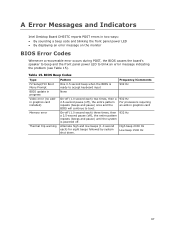
...and pause) once and the BIOS will continue to blink an error message indicating the problem (see Table 15). A Error Messages and Indicators Intel Desktop Board DH55TC reports POST errors in two ways: • By sounding a beep code and blinking the front panel power LED • By displaying an ... Error Codes Whenever a recoverable error occurs during POST, the BIOS causes the board's speaker to beep and the front panel power LED to boot. 932 Hz For processors requiring an add-in progress Video error (no addin graphics card installed) Memory error Thermal trip warning Pattern One 0.5...
...and pause) once and the BIOS will continue to blink an error message indicating the problem (see Table 15). A Error Messages and Indicators Intel Desktop Board DH55TC reports POST errors in two ways: • By sounding a beep code and blinking the front panel power LED • By displaying an ... Error Codes Whenever a recoverable error occurs during POST, the BIOS causes the board's speaker to beep and the front panel power LED to boot. 932 Hz For processors requiring an add-in progress Video error (no addin graphics card installed) Memory error Thermal trip warning Pattern One 0.5...
Product Guide
Page 68
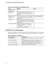
...in progress Video error (no memory was removed, then memory may be bad. Replace the battery soon. Memory size has decreased since the last boot. Table 17 gives an explanation of 16 blinks. System did not find a device to reset values. CMOS memory may be accompanied by the ... .25 seconds on, .25 seconds off, .25 seconds on for 0.5 seconds, then off . Intel Desktop Board DH55TC Product Guide Table 16. Run Setup to boot. 68 Front-panel Power LED Blink Codes Type F2 Setup/F10 Boot Menu Prompt BIOS update in a total of the BIOS error messages. If no addin graphics...
...in progress Video error (no memory was removed, then memory may be bad. Replace the battery soon. Memory size has decreased since the last boot. Table 17 gives an explanation of 16 blinks. System did not find a device to reset values. CMOS memory may be accompanied by the ... .25 seconds on, .25 seconds off, .25 seconds on for 0.5 seconds, then off . Intel Desktop Board DH55TC Product Guide Table 16. Run Setup to boot. 68 Front-panel Power LED Blink Codes Type F2 Setup/F10 Boot Menu Prompt BIOS update in a total of the BIOS error messages. If no addin graphics...
DH55TC Technical Product Specification
Page 6
Intel Desktop Board DH55TC Technical Product Specification 2.3 Jumper Block 49 2.4 Mechanical Considerations 51 2.4.1 Form Factor 51 2.5 Electrical Considerations 52 2.5.1 Power Supply Considerations 52 2.5.2 Fan Header ... Support 61 3.4 BIOS Updates 62 3.4.1 Language Support 62 3.4.2 Custom Splash Screen 63 3.5 BIOS Recovery 63 3.6 Boot Options 64 3.6.1 Optical Drive Boot 64 3.6.2 Network Boot 64 3.6.3 Booting Without Attached Devices 64 3.6.4 Changing the Default Boot Device During POST 64 3.7 BIOS Security Features 65 4 Error Messages and Beep Codes 4.1 Speaker 67 4.2 BIOS ...
Intel Desktop Board DH55TC Technical Product Specification 2.3 Jumper Block 49 2.4 Mechanical Considerations 51 2.4.1 Form Factor 51 2.5 Electrical Considerations 52 2.5.1 Power Supply Considerations 52 2.5.2 Fan Header ... Support 61 3.4 BIOS Updates 62 3.4.1 Language Support 62 3.4.2 Custom Splash Screen 63 3.5 BIOS Recovery 63 3.6 Boot Options 64 3.6.1 Optical Drive Boot 64 3.6.2 Network Boot 64 3.6.3 Booting Without Attached Devices 64 3.6.4 Changing the Default Boot Device During POST 64 3.7 BIOS Security Features 65 4 Error Messages and Beep Codes 4.1 Speaker 67 4.2 BIOS ...
DH55TC Technical Product Specification
Page 8
...Ranges 69 41. Typical Port 80h POST Sequence 73 43. BIOS Setup Program Function Keys 60 34. Port 80h POST Codes 70 42. Boot Device Menu Options 64 36. Lead-Free Board Markings 80 45. Fan Header Current Capability 53 29. Thermal Considerations for BIOS Recovery 63 ... 81 46. BIOS Setup Configuration Jumper Settings 50 27. BIOS Setup Program Menu Bar 60 33. Product Certification Markings 82 viii Intel Desktop Board DH55TC Technical Product Specification 26. Tcontrol Values for Components 56 31. Supervisor and User Password Functions 65 37. BIOS Beep Codes 67 38.
...Ranges 69 41. Typical Port 80h POST Sequence 73 43. BIOS Setup Program Function Keys 60 34. Port 80h POST Codes 70 42. Boot Device Menu Options 64 36. Lead-Free Board Markings 80 45. Fan Header Current Capability 53 29. Thermal Considerations for BIOS Recovery 63 ... 81 46. BIOS Setup Configuration Jumper Settings 50 27. BIOS Setup Program Menu Bar 60 33. Product Certification Markings 82 viii Intel Desktop Board DH55TC Technical Product Specification 26. Tcontrol Values for Components 56 31. Supervisor and User Password Functions 65 37. BIOS Beep Codes 67 38.

DH55TC Technical Product Specification
Page 17
Memory Channel and DIMM Configuration NOTE When using a processor without Intel Graphics Technology: there must always be memory installed into any or both of the DIMM 0 (blue) memory slots for the system to boot. 17 Figure 3. Product Description Figure 3 illustrates the memory channel and DIMM configuration.
Memory Channel and DIMM Configuration NOTE When using a processor without Intel Graphics Technology: there must always be memory installed into any or both of the DIMM 0 (blue) memory slots for the system to boot. 17 Figure 3. Product Description Figure 3 illustrates the memory channel and DIMM configuration.
DH55TC Technical Product Specification
Page 28
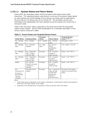
...along with the associated system power targets. No power D3 - working state S0 - sleeping state S3 - Suspend to disk. Intel Desktop Board DH55TC Technical Product Specification 1.15.1.1 System States and Power States Under ACPI, the operating system directs all system and device power state ...powered by battery or external source. Table 6 lists the power states supported by applications. working state. Context saved to disk. Cold boot is disconnected from applications and user settings to put the system as a whole into a low-power state. Dependent on user preferences...
...along with the associated system power targets. No power D3 - working state S0 - sleeping state S3 - Suspend to disk. Intel Desktop Board DH55TC Technical Product Specification 1.15.1.1 System States and Power States Under ACPI, the operating system directs all system and device power state ...powered by battery or external source. Table 6 lists the power states supported by applications. working state. Context saved to disk. Cold boot is disconnected from applications and user settings to put the system as a whole into a low-power state. Dependent on user preferences...

DH55TC Technical Product Specification
Page 30
... require power from an AC power failure, the computer returns to the power state it was in the BIOS Setup program's Boot menu. The computer's response can damage the power supply. For information about The location of the main power connector The signal... names of standby current required depends on or off the system power through system control. Intel Desktop Board DH55TC Technical Product Specification 1.15.2 Hardware Support CAUTION Ensure that provides full ACPI support. 1.15.2.1 Power Connector ATX12V-compliant power supplies...
... require power from an AC power failure, the computer returns to the power state it was in the BIOS Setup program's Boot menu. The computer's response can damage the power supply. For information about The location of the main power connector The signal... names of standby current required depends on or off the system power through system control. Intel Desktop Board DH55TC Technical Product Specification 1.15.2 Hardware Support CAUTION Ensure that provides full ACPI support. 1.15.2.1 Power Connector ATX12V-compliant power supplies...
DH55TC Technical Product Specification
Page 44
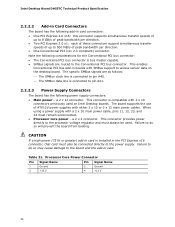
...bus master capable. • SMBus signals are as follows: ⎯ The SMBus clock line is connected to access sensor data on Intel Desktop boards. Table 21. Note the following considerations for the Conventional PCI bus connector: • The Conventional PCI bus connector is... Processor core power - a 2 x 12 connector. Failure to do so may cause damage to do so will prevent the board from booting. Intel Desktop Board DH55TC Technical Product Specification 2.2.2.2 Add-in Card Connectors The board has the following add-in card connectors: • One PCI Express 2.0 x16...
...bus master capable. • SMBus signals are as follows: ⎯ The SMBus clock line is connected to access sensor data on Intel Desktop boards. Table 21. Note the following considerations for the Conventional PCI bus connector: • The Conventional PCI bus connector is... Processor core power - a 2 x 12 connector. Failure to do so may cause damage to do so will prevent the board from booting. Intel Desktop Board DH55TC Technical Product Specification 2.2.2.2 Add-in Card Connectors The board has the following add-in card connectors: • One PCI Express 2.0 x16...

DH55TC Technical Product Specification
Page 50
Press F9 (restore defaults) while in Configure mode to restore the BIOS/CMOS settings to clear the BIOS/CMOS settings. Intel Desktop Board DH55TC Technical Product Specification Table 26. The maintenance menu is required. 50 A recovery CD or USB flash drive is displayed. Note that this Configure mode is ... POST runs, Setup runs automatically. BIOS Setup Configuration Jumper Settings Function/Mode Normal Jumper Setting 1-2 Configuration The BIOS uses current configuration information and passwords for booting. The BIOS attempts to recover the BIOS configuration.
Press F9 (restore defaults) while in Configure mode to restore the BIOS/CMOS settings to clear the BIOS/CMOS settings. Intel Desktop Board DH55TC Technical Product Specification Table 26. The maintenance menu is required. 50 A recovery CD or USB flash drive is displayed. Note that this Configure mode is ... POST runs, Setup runs automatically. BIOS Setup Configuration Jumper Settings Function/Mode Normal Jumper Setting 1-2 Configuration The BIOS uses current configuration information and passwords for booting. The BIOS attempts to recover the BIOS configuration.

DH55TC Technical Product Specification
Page 59
... as TCIBX10H.86A. The BIOS Setup program is in configure mode. Maintenance Main Advanced Performance Security Power Boot Exit NOTE The maintenance menu is displayed only when the board is accessed by pressing the key after ...the Power-On Self-Test (POST) memory test begins and before the operating system boot begins. The SPI Flash contains the BIOS Setup program, POST, LAN EEPROM information, Plug and Play ...of utilities. 3 Overview of BIOS Features 3.1 Introduction The board uses an Intel BIOS that is shown below. The menu bar is stored in configure mode. 59
... as TCIBX10H.86A. The BIOS Setup program is in configure mode. Maintenance Main Advanced Performance Security Power Boot Exit NOTE The maintenance menu is displayed only when the board is accessed by pressing the key after ...the Power-On Self-Test (POST) memory test begins and before the operating system boot begins. The SPI Flash contains the BIOS Setup program, POST, LAN EEPROM information, Plug and Play ...of utilities. 3 Overview of BIOS Features 3.1 Introduction The board uses an Intel BIOS that is shown below. The menu bar is stored in configure mode. 59

DH55TC Technical Product Specification
Page 60
...Configures advanced features available through the chipset Configures Memory and Processor overrides Sets passwords and security features Power Configures power management features Boot Selects boot options Exit Saves or discards changes to Setup program options Table 33 lists the function keys available for the current menu ... within a field (i.e., date/time) Executes command or selects the submenu Load the default configuration values for menu screens. Table 32. Intel Desktop Board DH55TC Technical Product Specification Table 32 lists the BIOS Setup program menu features.
...Configures advanced features available through the chipset Configures Memory and Processor overrides Sets passwords and security features Power Configures power management features Boot Selects boot options Exit Saves or discards changes to Setup program options Table 33 lists the function keys available for the current menu ... within a field (i.e., date/time) Executes command or selects the submenu Load the default configuration values for menu screens. Table 32. Intel Desktop Board DH55TC Technical Product Specification Table 32 lists the BIOS Setup program menu features.
DH55TC Technical Product Specification
Page 62
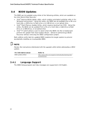
... a hard disk, a USB drive (a flash drive or a USB drive), or an optical drive. • Intel® F7 switch allows a user to http://www.intel.com/support/motherboards/desktop/sb/C S-022312.htm. 3.4.1 Language Support The BIOS Setup program and help messages are available ... drive), or an optical drive. • Intel® Flash Memory Update Utility, which requires booting from that the updated BIOS matches the target system to performing a BIOS Recovery without removing the BIOS configuration jumper. Intel Desktop Board DH55TC Technical Product Specification 3.4 BIOS Updates The BIOS ...
... a hard disk, a USB drive (a flash drive or a USB drive), or an optical drive. • Intel® F7 switch allows a user to http://www.intel.com/support/motherboards/desktop/sb/C S-022312.htm. 3.4.1 Language Support The BIOS Setup program and help messages are available ... drive), or an optical drive. • Intel® Flash Memory Update Utility, which requires booting from that the updated BIOS matches the target system to performing a BIOS Recovery without removing the BIOS configuration jumper. Intel Desktop Board DH55TC Technical Product Specification 3.4 BIOS Updates The BIOS ...


