
Product Guide
Page 3
...) for installation in homes, offices, schools, computer rooms, and similar locations. may not be supported without further evaluation by Intel. iii Intended Audience The Product Guide is not intended for Intel® Desktop Board DH55TC. Use Only for Intended Applications All Intel Desktop Boards are used in this Product Guide are arranged as follows: 1 Desktop Board Features: a summary of this manual: CAUTION Cautions warn the user about BIOS error messages and beep codes...
...) for installation in homes, offices, schools, computer rooms, and similar locations. may not be supported without further evaluation by Intel. iii Intended Audience The Product Guide is not intended for Intel® Desktop Board DH55TC. Use Only for Intended Applications All Intel Desktop Boards are used in this Product Guide are arranged as follows: 1 Desktop Board Features: a summary of this manual: CAUTION Cautions warn the user about BIOS error messages and beep codes...

Product Guide
Page 5
... Intel® H55 Express Chipset 14 Main Memory...15 Graphics Subsystem 15 Integrated Graphics 15 Analog Display (VGA 15 High-Definition Multimedia Interface* (HDMI 16 Digital Visual Interface (DVI-D 16 PCI Express* x16 Graphics 16 Audio Subsystem 16 LAN Subsystem 17 USB 2.0 Support 18 Serial ATA Support 18 Expandability...18 Legacy I/O ...19 BIOS ...19 Serial ATA Auto Configuration 19 PCI*/PCI Express Auto Configuration 19 Security Passwords 19 Hardware Management 20 Hardware Monitoring and Fan Speed Control 20 Fan Monitoring 20 Power Management 21 Software Support 21 ACPI...
... Intel® H55 Express Chipset 14 Main Memory...15 Graphics Subsystem 15 Integrated Graphics 15 Analog Display (VGA 15 High-Definition Multimedia Interface* (HDMI 16 Digital Visual Interface (DVI-D 16 PCI Express* x16 Graphics 16 Audio Subsystem 16 LAN Subsystem 17 USB 2.0 Support 18 Serial ATA Support 18 Expandability...18 Legacy I/O ...19 BIOS ...19 Serial ATA Auto Configuration 19 PCI*/PCI Express Auto Configuration 19 Security Passwords 19 Hardware Management 20 Hardware Monitoring and Fan Speed Control 20 Fan Monitoring 20 Power Management 21 Software Support 21 ACPI...
Product Guide
Page 6
...PCI Express x16 Graphics Card 42 Connecting Serial ATA (SATA) Cables 44 Installing an Intel® Z-U130 USB Solid-State Drive (or Compatible Device 45 Connecting to the Internal Headers 46 Front Panel Audio Header 47 Internal Mono Speaker Header 47 S/PDIF Header 48 Parallel Port Header 48 Alternate Front Panel Power LED Header 49 Front Panel Header 49 Front Panel USB 2.0 Headers 50 Serial Header 51 Connecting to the Audio System 51 Connecting Chassis Fan and Power Supply Cables 52 Connecting Chassis Fan Cables 52 Connecting Power Supply Cables 53 Setting the BIOS Configuration...
...PCI Express x16 Graphics Card 42 Connecting Serial ATA (SATA) Cables 44 Installing an Intel® Z-U130 USB Solid-State Drive (or Compatible Device 45 Connecting to the Internal Headers 46 Front Panel Audio Header 47 Internal Mono Speaker Header 47 S/PDIF Header 48 Parallel Port Header 48 Alternate Front Panel Power LED Header 49 Front Panel Header 49 Front Panel USB 2.0 Headers 50 Serial Header 51 Connecting to the Audio System 51 Connecting Chassis Fan and Power Supply Cables 52 Connecting Chassis Fan Cables 52 Connecting Power Supply Cables 53 Setting the BIOS Configuration...
Product Guide
Page 7
... vii Connecting the Processor Fan Heat Sink Power Cable to the Processor Fan Header 36 14. Lower the Load Plate 35 12. Example Dual Channel Memory Configuration with Three DIMMs 38 17. Connecting a Serial ATA Cable 44 22. LAN Connector LEDs 17 3. Unlatch the Socket Lever 31 7. Remove the Processor from the Protective Cover 34 10. Internal Headers 46 24. Connecting Power Supply Cables 53 27. Use DDR3 DIMMs 39 18. Intel Desktop Board DH55TC Mounting Screw Hole Locations 30 6. Installing the I/O Shield 29 5. Remove the Socket...
... vii Connecting the Processor Fan Heat Sink Power Cable to the Processor Fan Header 36 14. Lower the Load Plate 35 12. Example Dual Channel Memory Configuration with Three DIMMs 38 17. Connecting a Serial ATA Cable 44 22. LAN Connector LEDs 17 3. Unlatch the Socket Lever 31 7. Remove the Processor from the Protective Cover 34 10. Internal Headers 46 24. Connecting Power Supply Cables 53 27. Use DDR3 DIMMs 39 18. Intel Desktop Board DH55TC Mounting Screw Hole Locations 30 6. Installing the I/O Shield 29 5. Remove the Socket...
Product Guide
Page 8
... Panel Audio Header Signal Names for Intel HD Audio 47 5. Parallel Port Header 48 9. Serial Port Header 51 14. BIOS Error Messages 68 18. BIOS Beep Codes 67 16. Safety Standards 69 19. Front Panel Audio Signal Names for AC '97 Audio 47 6. Intel Desktop Board DH55TC Product Guide Tables 1. Feature Summary 9 2. LAN Connector LEDs 18 4. Internal Mono Speaker Header 47 7. S/PDIF Header Signal Names 48 8. Alternate Front Panel Power LED Header Signal Names 49 10. Front Panel Header Signal Names 49 11. Jumper Settings for the BIOS Setup Program Modes...
... Panel Audio Header Signal Names for Intel HD Audio 47 5. Parallel Port Header 48 9. Serial Port Header 51 14. BIOS Error Messages 68 18. BIOS Beep Codes 67 16. Safety Standards 69 19. Front Panel Audio Signal Names for AC '97 Audio 47 6. Intel Desktop Board DH55TC Product Guide Tables 1. Feature Summary 9 2. LAN Connector LEDs 18 4. Internal Mono Speaker Header 47 7. S/PDIF Header Signal Names 48 8. Alternate Front Panel Power LED Header Signal Names 49 10. Front Panel Header Signal Names 49 11. Jumper Settings for the BIOS Setup Program Modes...
Product Guide
Page 10
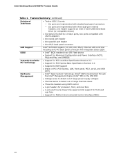
... 3-wire (linear) fan speed control support for front and rear fans • Support for Platform Environmental Control Interface (PECI) 10 one header supports an Intel Z-U130 USB Solid-State Drive (or compatible device) • Six Serial ATA (SATA) 3.0 Gb/s ports, two ports compatible with eSATA adapters • One serial port header • One parallel port header • One PS/2 back panel connector Intel® 82578DC Gigabit (10/100/1000 Mb/s) Ethernet LAN controller including an RJ-45 back panel connector with three dual-port internal headers; Intel Desktop Board DH55TC...
... 3-wire (linear) fan speed control support for front and rear fans • Support for Platform Environmental Control Interface (PECI) 10 one header supports an Intel Z-U130 USB Solid-State Drive (or compatible device) • Six Serial ATA (SATA) 3.0 Gb/s ports, two ports compatible with eSATA adapters • One serial port header • One parallel port header • One PS/2 back panel connector Intel® 82578DC Gigabit (10/100/1000 Mb/s) Ethernet LAN controller including an RJ-45 back panel connector with three dual-port internal headers; Intel Desktop Board DH55TC...
Product Guide
Page 19
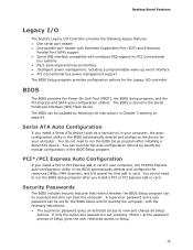
... PCI Express and SATA auto-configuration utilities. The BIOS is set for the BIOS Setup and for booting the computer, with the following legacy features: • One serial port header • One parallel port header with Extended Capabilities Port (ECP) and Enhanced Parallel Port (EPP) support • Serial IRQ interface compatible with serialized IRQ support for PCI Conventional bus systems • PS/2-style keyboard/mouse interface • Intelligent power management, including a programmable wake-up event interface • PCI Conventional bus power management support...
... PCI Express and SATA auto-configuration utilities. The BIOS is set for the BIOS Setup and for booting the computer, with the following legacy features: • One serial port header • One parallel port header with Extended Capabilities Port (ECP) and Enhanced Parallel Port (EPP) support • Serial IRQ interface compatible with serialized IRQ support for PCI Conventional bus systems • PS/2-style keyboard/mouse interface • Intelligent power management, including a programmable wake-up event interface • PCI Conventional bus power management support...

Product Guide
Page 21
.... • Each fan header is wired to RAM) • +5 V standby power indicator LED • Wake from USB • PCI Power Management Event signal (PME#) wakeup support • PCI Express WAKE# signal support • Wake from PS/2 devices • Wake from serial port Software Support ACPI ACPI gives the operating system direct control over the power management and Plug and Play functions of the fans is as needed. 21 The use of the power connectors. The Desktop Board has two power connectors. Desktop Board Features Power Management Power management is...
.... • Each fan header is wired to RAM) • +5 V standby power indicator LED • Wake from USB • PCI Power Management Event signal (PME#) wakeup support • PCI Express WAKE# signal support • Wake from PS/2 devices • Wake from serial port Software Support ACPI ACPI gives the operating system direct control over the power management and Plug and Play functions of the fans is as needed. 21 The use of the power connectors. The Desktop Board has two power connectors. Desktop Board Features Power Management Power management is...

Product Guide
Page 27
... Disconnect the computer from its power source and from any telecommunications links, networks, or modems before you how to: • Install the I/O shield • Install and remove the Desktop Board • Install and remove a processor • Install and remove memory • Install and remove a PCI Express x16 card • Connect Serial ATA cables • Install an Intel Z-U130 USB Solid-State Drive (or Compatible Device) • Connect to the internal headers and connectors • Connect to a metal part of the procedures described in...
... Disconnect the computer from its power source and from any telecommunications links, networks, or modems before you how to: • Install the I/O shield • Install and remove the Desktop Board • Install and remove a processor • Install and remove memory • Install and remove a PCI Express x16 card • Connect Serial ATA cables • Install an Intel Z-U130 USB Solid-State Drive (or Compatible Device) • Connect to the internal headers and connectors • Connect to a metal part of the procedures described in...
Product Guide
Page 41
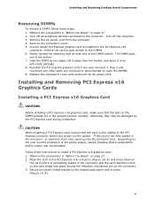
Turn off all peripheral devices connected to the chassis back panel with a screw (Figure 19, B). 41 Gently spread the retaining clips at each end of the socket. 7. Hold the DIMM by the PCI Express card during installation. Installing and Removing PCI Express x16 Graphics Cards Installing a PCI Express x16 Graphics Card CAUTION Before installing a PCI Express x16 graphics card, make sure that the card is fully seated in the PCI Express connector before you removed or disconnected to reach the DIMMs. 9. The...
Turn off all peripheral devices connected to the chassis back panel with a screw (Figure 19, B). 41 Gently spread the retaining clips at each end of the socket. 7. Hold the DIMM by the PCI Express card during installation. Installing and Removing PCI Express x16 Graphics Cards Installing a PCI Express x16 Graphics Card CAUTION Before installing a PCI Express x16 graphics card, make sure that the card is fully seated in the PCI Express connector before you removed or disconnected to reach the DIMMs. 9. The...

Product Guide
Page 55
... board is set to boot. 7. Observe the precautions in the computer and the configuration jumper block is installed in "Before You Begin" on pins 2-3 as shown below. 6. Turn off all peripheral devices connected to clear passwords. Disconnect the computer's power cord from the AC power source (wall outlet or power adapter). 3. Setup displays the Maintenance menu. 55 Remove the computer cover. 4. Jumper Settings for the BIOS Setup Program Modes Jumper Setting Mode Normal (default) (1-2) Description The BIOS uses the current configuration...
... board is set to boot. 7. Observe the precautions in the computer and the configuration jumper block is installed in "Before You Begin" on pins 2-3 as shown below. 6. Turn off all peripheral devices connected to clear passwords. Disconnect the computer's power cord from the AC power source (wall outlet or power adapter). 3. Setup displays the Maintenance menu. 55 Remove the computer cover. 4. Jumper Settings for the BIOS Setup Program Modes Jumper Setting Mode Normal (default) (1-2) Description The BIOS uses the current configuration...
Product Guide
Page 63
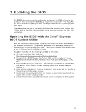
... the last Express BIOS Update window. 5. The BIOS file is required. This is useful if you how to update the BIOS by pressing the key after the Power-On Self-Test (POST) memory test begins and before the operating system boot begins. Go to the DH55TC page, click "Latest BIOS and driver updates," select "BIOS Update [TCIBX10H.86A]," and download the Express BIOS Update utility file. 3. Navigate to the Intel World Wide Web site: http://support.intel.com/support/motherboards/desktop/ 2. This...
... the last Express BIOS Update window. 5. The BIOS file is required. This is useful if you how to update the BIOS by pressing the key after the Power-On Self-Test (POST) memory test begins and before the operating system boot begins. Go to the DH55TC page, click "Latest BIOS and driver updates," select "BIOS Update [TCIBX10H.86A]," and download the Express BIOS Update utility file. 3. Navigate to the Intel World Wide Web site: http://support.intel.com/support/motherboards/desktop/ 2. This...
DH55TC Technical Product Specification
Page 7
... Rear Chassis Fan Headers 43 21. Major Board Components 11 2. Back Panel Connectors 38 10. Connection Diagram for a One-Color Power LED 47 25. Front Panel Audio Header for Front Panel USB Headers 48 13. Memory Channel and DIMM Configuration 17 4. Internal Mono Speaker Header 42 14. Front Panel USB Header 42 17. States for Front Panel USB Header (with Intel Z-U130 USB Solid-State Drive, or Compatible Device, Support 43 18. Back Panel Audio Connector Options 22 5. Component-side Connectors and Headers 39 11. Board Dimensions 51 16. Localized High Temperature Zones...
... Rear Chassis Fan Headers 43 21. Major Board Components 11 2. Back Panel Connectors 38 10. Connection Diagram for a One-Color Power LED 47 25. Front Panel Audio Header for Front Panel USB Headers 48 13. Memory Channel and DIMM Configuration 17 4. Internal Mono Speaker Header 42 14. Front Panel USB Header 42 17. States for Front Panel USB Header (with Intel Z-U130 USB Solid-State Drive, or Compatible Device, Support 43 18. Back Panel Audio Connector Options 22 5. Component-side Connectors and Headers 39 11. Board Dimensions 51 16. Localized High Temperature Zones...
DH55TC Technical Product Specification
Page 8
.... Environmental Specifications 57 32. BIOS Error Messages 68 40. Product Certification Markings 82 viii Thermal Considerations for Components 56 31. Port 80h POST Code Ranges 69 41. Typical Port 80h POST Sequence 73 43. Safety Standards 75 44. AcceptableDrives/Media Types for BIOS Recovery 63 35. Minimum Recommended Power Supply Current Values 52 28. Boot Device Menu Options 64 36. Front-panel Power LED Blink Codes 68 39. Intel Desktop Board DH55TC Technical Product Specification 26.
.... Environmental Specifications 57 32. BIOS Error Messages 68 40. Product Certification Markings 82 viii Thermal Considerations for Components 56 31. Port 80h POST Code Ranges 69 41. Typical Port 80h POST Sequence 73 43. Safety Standards 75 44. AcceptableDrives/Media Types for BIOS Recovery 63 35. Minimum Recommended Power Supply Current Values 52 28. Boot Device Menu Options 64 36. Front-panel Power LED Blink Codes 68 39. Intel Desktop Board DH55TC Technical Product Specification 26.
DH55TC Technical Product Specification
Page 48
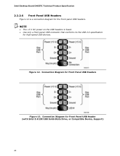
Connection Diagram for Front Panel USB Headers Figure 13. Connection Diagram for Front Panel USB Header (with Intel Z-U130 USB Solid-State Drive, or Compatible Device, Support) 48 Intel Desktop Board DH55TC Technical Product Specification 2.2.2.6 Front Panel USB Headers Figure 12 is fused. • Use only a front panel USB connector that conforms to the USB 2.0 specification for the front panel USB headers. Figure 12. NOTE • The +5 V DC power on the USB headers is a connection diagram for high-speed USB devices.
Connection Diagram for Front Panel USB Headers Figure 13. Connection Diagram for Front Panel USB Header (with Intel Z-U130 USB Solid-State Drive, or Compatible Device, Support) 48 Intel Desktop Board DH55TC Technical Product Specification 2.2.2.6 Front Panel USB Headers Figure 12 is fused. • Use only a front panel USB connector that conforms to the USB 2.0 specification for the front panel USB headers. Figure 12. NOTE • The +5 V DC power on the USB headers is a connection diagram for high-speed USB devices.
DH55TC Technical Product Specification
Page 68
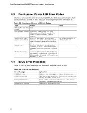
... . CMOS memory may be losing power. Note For processors requiring an add-in a total of each. Table 39. Replace the battery soon. Intel Desktop Board DH55TC Technical Product Specification 4.3 Front-panel Power LED Blink Codes Whenever a recoverable error occurs during POST, the BIOS causes the board's front panel power LED to reset values. Thermal trip warning Each beep will result in graphics card 4.4 BIOS Error Messages Table 39 lists the error messages and provides a brief description of 16 blinks. No Boot Device...
... . CMOS memory may be losing power. Note For processors requiring an add-in a total of each. Table 39. Replace the battery soon. Intel Desktop Board DH55TC Technical Product Specification 4.3 Front-panel Power LED Blink Codes Whenever a recoverable error occurs during POST, the BIOS causes the board's front panel power LED to reset values. Thermal trip warning Each beep will result in graphics card 4.4 BIOS Error Messages Table 39 lists the error messages and provides a brief description of 16 blinks. No Boot Device...
DH55TC Technical Product Specification
Page 69
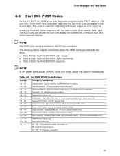
... Host Processors: 1F is an unrecoverable CPU error. 20 - 2F Memory/Chipset: 2F is no memory detected or no useful memory detected. 30 - 3F Recovery: 3F indicated recovery failure. 40 - 4F Reserved for future use (new output console codes). 90 - 9F Input devices: Keyboard/Mouse. 9F is an unrecoverable error. Table 40. Start with PCI. 60 - 6F 70 - 7F Reserved for future use. 50 - 5F I /O port 80h. B0 - If the POST...
... Host Processors: 1F is an unrecoverable CPU error. 20 - 2F Memory/Chipset: 2F is no memory detected or no useful memory detected. 30 - 3F Recovery: 3F indicated recovery failure. 40 - 4F Reserved for future use (new output console codes). 90 - 9F Input devices: Keyboard/Mouse. 9F is an unrecoverable error. Table 40. Start with PCI. 60 - 6F 70 - 7F Reserved for future use. 50 - 5F I /O port 80h. B0 - If the POST...
DH55TC Technical Product Specification
Page 73
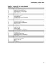
... POST Code Description 21 Initializing a chipset component 22 Reading SPD from memory DIMMs 23 Detecting presence of memory DIMMs 25 Configuring memory 28 Testing memory 34 Loading recovery capsule E4 Entered DXE phase 12 Starting application processor initialization 13 SMM initialization 50 Enumerating PCI busses 51 Allocating resourced to PCI bus 92 Detecting the presence of the keyboard 90 Resetting keyboard 94 Clearing keyboard input buffer 95 Keyboard Self Test EB Calling Video BIOS...
... POST Code Description 21 Initializing a chipset component 22 Reading SPD from memory DIMMs 23 Detecting presence of memory DIMMs 25 Configuring memory 28 Testing memory 34 Loading recovery capsule E4 Entered DXE phase 12 Starting application processor initialization 13 SMM initialization 50 Enumerating PCI busses 51 Allocating resourced to PCI bus 92 Detecting the presence of the keyboard 90 Resetting keyboard 94 Clearing keyboard input buffer 95 Keyboard Self Test EB Calling Video BIOS...
DH55TC Specification Update
Page 6
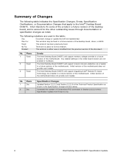
... BIOS. Plans 1 Doc 2 Doc Specification Changes Updated Section 2.2.2.2 and Section 2.2.2.6 of the motherboard. Summary of the motherboard does not provide such header. Corrected the number of Conventional PCI connectors in a future revision of the motherboard. No. 1 Plans Fixed 2 Fixed 3 Fixed Errata The Intel Desktop Board DH55TC will support triggering Intel® Remote PC Assist Technology via a header in a future revision of the desktop board, and to one. 6 Intel Desktop Board DH55TC Specification Update The Intel Desktop Board DH55TC will support memory voltage...
... BIOS. Plans 1 Doc 2 Doc Specification Changes Updated Section 2.2.2.2 and Section 2.2.2.6 of the motherboard. Summary of the motherboard does not provide such header. Corrected the number of Conventional PCI connectors in a future revision of the motherboard. No. 1 Plans Fixed 2 Fixed 3 Fixed Errata The Intel Desktop Board DH55TC will support triggering Intel® Remote PC Assist Technology via a header in a future revision of the desktop board, and to one. 6 Intel Desktop Board DH55TC Specification Update The Intel Desktop Board DH55TC will support memory voltage...
DH55TC Specification Update
Page 7
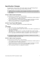
... Conventional PCI (rev 2.3 compliant) connectors. Intel Desktop Board DH55TC Specification Update 7 NOTES • The +5 V DC power on the USB headers is a connection diagram for high-speed USB devices. • USB Header 2 (FP USB 2) has Pin 10 routed to the HDD LED to support specific USB SSD devices. Corrected the number of Conventional PCI connectors in Section 2.2.2.2 of this Specification Update from three to one. 2.2.2.2 Add-in Card Connectors The board has the following add-in card connectors: • One PCI Express 2.0 x16: this connector supports simultaneous transfer speeds of...
... Conventional PCI (rev 2.3 compliant) connectors. Intel Desktop Board DH55TC Specification Update 7 NOTES • The +5 V DC power on the USB headers is a connection diagram for high-speed USB devices. • USB Header 2 (FP USB 2) has Pin 10 routed to the HDD LED to support specific USB SSD devices. Corrected the number of Conventional PCI connectors in Section 2.2.2.2 of this Specification Update from three to one. 2.2.2.2 Add-in Card Connectors The board has the following add-in card connectors: • One PCI Express 2.0 x16: this connector supports simultaneous transfer speeds of...


