
Product Guide
Page 2
...the Radio Interference Regulations of the Canadian Department of the FCC Rules. Disclaimer INFORMATION IN THIS DOCUMENT IS PROVIDED IN CONNECTION WITH INTEL® PRODUCTS. Intel is a trademark of others. Elam Young Parkway, Hillsboro, OR 97124 1-800-628-8686 This equipment has been tested... to which the receiver is connected. • Consult the dealer or an experienced radio/TV technician for radio noise emissions from published specifications. Revision History Revision -001 Revision History First release of the Intel® Desktop Board DH55TC Product Guide Date October 2009 ...
...the Radio Interference Regulations of the Canadian Department of the FCC Rules. Disclaimer INFORMATION IN THIS DOCUMENT IS PROVIDED IN CONNECTION WITH INTEL® PRODUCTS. Intel is a trademark of others. Elam Young Parkway, Hillsboro, OR 97124 1-800-628-8686 This equipment has been tested... to which the receiver is connected. • Consult the dealer or an experienced radio/TV technician for radio noise emissions from published specifications. Revision History Revision -001 Revision History First release of the Intel® Desktop Board DH55TC Product Guide Date October 2009 ...
Product Guide
Page 6
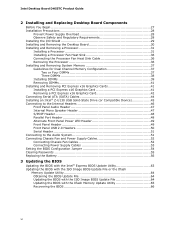
Intel Desktop Board DH55TC Product Guide 2 Installing and Replacing Desktop Board Components Before You ... Board 30 Installing and Removing a Processor 31 Installing a Processor 31 Installing a Processor Fan Heat Sink 36 Connecting the Processor Fan Heat Sink Cable 36 Removing the Processor 36 Installing and Removing System Memory 37 Guidelines for ... Card 41 Removing a PCI Express x16 Graphics Card 42 Connecting Serial ATA (SATA) Cables 44 Installing an Intel® Z-U130 USB Solid-State Drive (or Compatible Device 45 Connecting to the Internal Headers 46 Front Panel Audio Header 47 ...
Intel Desktop Board DH55TC Product Guide 2 Installing and Replacing Desktop Board Components Before You ... Board 30 Installing and Removing a Processor 31 Installing a Processor 31 Installing a Processor Fan Heat Sink 36 Connecting the Processor Fan Heat Sink Cable 36 Removing the Processor 36 Installing and Removing System Memory 37 Guidelines for ... Card 41 Removing a PCI Express x16 Graphics Card 42 Connecting Serial ATA (SATA) Cables 44 Installing an Intel® Z-U130 USB Solid-State Drive (or Compatible Device 45 Connecting to the Internal Headers 46 Front Panel Audio Header 47 ...
Product Guide
Page 7
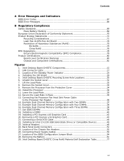
...Memory Configuration with Two DIMMs 37 15. Installing a DIMM 40 19. Removing a PCI Express x16 Graphics Card 43 21. Installing an Intel Z-U130 USB Solid-State Drive (or Compatible Device 45 23. Location of Hazardous Substances (RoHS 75 EU RoHS 75 China RoHS 76...8. Location of the Standby Power Indicator 23 4. Intel Desktop Board DH55TC Components 12 2. Intel Desktop Board DH55TC Mounting Screw Hole Locations 30 6. Use DDR3 DIMMs 39 18. Back Panel Audio Connectors 51 25. Remove the Socket Cover 33 9. Connecting Power Supply Cables 53 27. Location of the Chassis...
...Memory Configuration with Two DIMMs 37 15. Installing a DIMM 40 19. Removing a PCI Express x16 Graphics Card 43 21. Installing an Intel Z-U130 USB Solid-State Drive (or Compatible Device 45 23. Location of Hazardous Substances (RoHS 75 EU RoHS 75 China RoHS 76...8. Location of the Standby Power Indicator 23 4. Intel Desktop Board DH55TC Components 12 2. Intel Desktop Board DH55TC Mounting Screw Hole Locations 30 6. Use DDR3 DIMMs 39 18. Back Panel Audio Connectors 51 25. Remove the Socket Cover 33 9. Connecting Power Supply Cables 53 27. Location of the Chassis...
Product Guide
Page 14
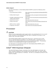
... Board Support http://support.intel.com/support/motherboards/deskt op/DH55TC • Available configurations for the board's I/O paths. 14 Intel Desktop Board DH55TC supports the Intel Core i7, and Intel Core i5, Intel Core i3, and Intel Pentium processors in damage to the board, or the system may not function properly. The processor connects to the processor and the...
... Board Support http://support.intel.com/support/motherboards/deskt op/DH55TC • Available configurations for the board's I/O paths. 14 Intel Desktop Board DH55TC supports the Intel Core i7, and Intel Core i5, Intel Core i3, and Intel Pentium processors in damage to the board, or the system may not function properly. The processor connects to the processor and the...
Product Guide
Page 16
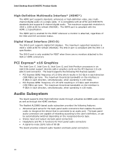
... enables the audio codec to recognize the device that is connected to the VGA or HDMI connectors. The maximum theoretical bandwidth on the recognized device type. • Stereo input and output via the PCI Express 2.0 x16 add-in card connector. Intel Desktop Board DH55TC Product Guide High-Definition Multimedia Interface* (HDMI*) The HDMI...
... enables the audio codec to recognize the device that is connected to the VGA or HDMI connectors. The maximum theoretical bandwidth on the recognized device type. • Stereo input and output via the PCI Express 2.0 x16 add-in card connector. Intel Desktop Board DH55TC Product Guide High-Definition Multimedia Interface* (HDMI*) The HDMI...

Product Guide
Page 17
... or 4 Ω at http://downloadcenter.intel.com/. The onboard S/PDIF header allows connection to an internal, lowpower speaker for basic system sound capability. Audio software and drivers are available at 1.5 W (rms). LAN Subsystem The LAN subsystem includes: • Intel 82578DC Gigabit (10/100/1000 Mb/s) ...for digital audio output. Figure 2. LAN Connector LEDs 17 Two LEDs are configurable through speakers connected to the back panel audio connectors and a headset connected to front panel audio connectors). The subsystem is supported by a separate audio channel pair, ...
... or 4 Ω at http://downloadcenter.intel.com/. The onboard S/PDIF header allows connection to an internal, lowpower speaker for basic system sound capability. Audio software and drivers are available at 1.5 W (rms). LAN Subsystem The LAN subsystem includes: • Intel 82578DC Gigabit (10/100/1000 Mb/s) ...for digital audio output. Figure 2. LAN Connector LEDs 17 Two LEDs are configurable through speakers connected to the back panel audio connectors and a headset connected to front panel audio connectors). The subsystem is supported by a separate audio channel pair, ...
Product Guide
Page 22
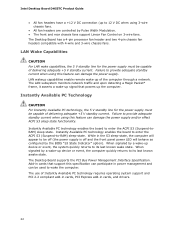
... V DC when using 3-wire chassis fans. • All fan headers are controlled by the BIOS "S3 State Indicator" option). Intel Desktop Board DH55TC Product Guide • All fan headers have a +12 V DC connection (up device or event, the computer quickly returns to its last known wake state. LAN Wake Capabilities CAUTION For LAN...
... V DC when using 3-wire chassis fans. • All fan headers are controlled by the BIOS "S3 State Indicator" option). Intel Desktop Board DH55TC Product Guide • All fan headers have a +12 V DC connection (up device or event, the computer quickly returns to its last known wake state. LAN Wake Capabilities CAUTION For LAN...
Product Guide
Page 23
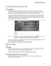
... and the PCI bus connectors. The Desktop Board's standby power indicator, shown in Figure 3, is lit when there is still present at http://support.intel.com/support/motherboards/desktop/ Wake from USB NOTE Wake from USB. Figure 3. PCI PME# Signal Wake-up Support When the PME# signal on standby... V Standby Power Indicator LED CAUTION If the AC power has been switched off . Failure to do so could damage the board and any devices connected to the board. Location of a USB peripheral that supports Wake from USB and an operating system that supports Wake from USB requires the use of...
... and the PCI bus connectors. The Desktop Board's standby power indicator, shown in Figure 3, is lit when there is still present at http://support.intel.com/support/motherboards/desktop/ Wake from USB NOTE Wake from USB. Figure 3. PCI PME# Signal Wake-up Support When the PME# signal on standby... V Standby Power Indicator LED CAUTION If the AC power has been switched off . Failure to do so could damage the board and any devices connected to the board. Location of a USB peripheral that supports Wake from USB and an operating system that supports Wake from USB requires the use of...

Product Guide
Page 27
... • Install and remove a PCI Express x16 card • Connect Serial ATA cables • Install an Intel Z-U130 USB Solid-State Drive (or Compatible Device) • Connect to the internal headers and connectors • Connect to a metal part of the procedures described in this chapter only ...Electrostatic discharge (ESD) can provide some ESD protection by wearing an antistatic wrist strap and attaching it to the audio system • Connect chassis fan and power supply cables • Set the BIOS configuration jumper • Clear passwords • Replace the battery Before You ...
... • Install and remove a PCI Express x16 card • Connect Serial ATA cables • Install an Intel Z-U130 USB Solid-State Drive (or Compatible Device) • Connect to the internal headers and connectors • Connect to a metal part of the procedures described in this chapter only ...Electrostatic discharge (ESD) can provide some ESD protection by wearing an antistatic wrist strap and attaching it to the audio system • Connect chassis fan and power supply cables • Set the BIOS configuration jumper • Clear passwords • Replace the battery Before You ...
Product Guide
Page 36
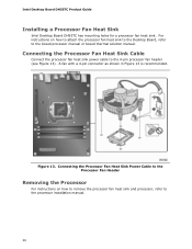
...36 Connecting the Processor Fan Heat Sink Power Cable to the Processor Fan Header Removing the Processor For instructions on how to attach the processor fan heat sink to the Desktop Board, refer to the boxed processor manual or boxed thermal solution manual. Intel Desktop Board DH55TC Product ...Guide Installing a Processor Fan Heat Sink Intel Desktop Board DH55TC has mounting holes for a processor fan heat sink. Figure 13. For instructions on how to ...
...36 Connecting the Processor Fan Heat Sink Power Cable to the Processor Fan Header Removing the Processor For instructions on how to attach the processor fan heat sink to the Desktop Board, refer to the boxed processor manual or boxed thermal solution manual. Intel Desktop Board DH55TC Product ...Guide Installing a Processor Fan Heat Sink Intel Desktop Board DH55TC has mounting holes for a processor fan heat sink. Figure 13. For instructions on how to ...

Product Guide
Page 40
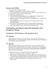
Observe the precautions in place. 10. Figure 18. Make sure the clips are pushed outward to the open position. 6. Intel Desktop Board DH55TC Product Guide To install a DIMM, follow these steps: 1. If a full length PCI Express graphics card is inserted, push down on page 27. 2. Installing a DIMM ...computer's cover and reconnect the AC power cord. 40 Turn off the computer and disconnect the AC power cord. 3. Turn off all peripheral devices connected to the DIMM sockets. Insert the bottom edge of the DIMM socket(s) are firmly in "Before You Begin" on the top edge of the...
Observe the precautions in place. 10. Figure 18. Make sure the clips are pushed outward to the open position. 6. Intel Desktop Board DH55TC Product Guide To install a DIMM, follow these steps: 1. If a full length PCI Express graphics card is inserted, push down on page 27. 2. Installing a DIMM ...computer's cover and reconnect the AC power cord. 40 Turn off the computer and disconnect the AC power cord. 3. Turn off all peripheral devices connected to the DIMM sockets. Insert the bottom edge of the DIMM socket(s) are firmly in "Before You Begin" on the top edge of the...
Product Guide
Page 41
... card if one was removed in the upright position (closed); Observe the precautions in "Before You Begin" on the system. Turn off all peripheral devices connected to the chassis back panel with a screw (Figure 19, B). 41 The DIMM pops out of the DIMM socket. Replace the computer's cover and reconnect the...
... card if one was removed in the upright position (closed); Observe the precautions in "Before You Begin" on the system. Turn off all peripheral devices connected to the chassis back panel with a screw (Figure 19, B). 41 The DIMM pops out of the DIMM socket. Replace the computer's cover and reconnect the...

Product Guide
Page 42
Intel Desktop Board DH55TC Product Guide 4. Disconnect the monitor cable from the connector (C). 5. Connect a monitor to the graphics card according to remove a PCI Express x16 graphics card from a connector: 1. Observe the precautions in the notch. Installing a PCI Express x16 ...
Intel Desktop Board DH55TC Product Guide 4. Disconnect the monitor cable from the connector (C). 5. Connect a monitor to the graphics card according to remove a PCI Express x16 graphics card from a connector: 1. Observe the precautions in the notch. Installing a PCI Express x16 ...

Product Guide
Page 44
Figure 21. Each cable can be used to connect one of the SATA connectors on page 27. 2. Attach one end of the SATA cable to one internal SATA drive to the SATA drive (Figure 21, B). Connecting a Serial ATA Cable 44 Observe the precautions in "Before You Begin" on the board (Figure 21, A) and attach the other end of the cable to the Desktop Board. For correct cable function: 1. Intel Desktop Board DH55TC Product Guide Connecting Serial ATA (SATA) Cables SATA cables support the Serial ATA protocol.
Figure 21. Each cable can be used to connect one of the SATA connectors on page 27. 2. Attach one end of the SATA cable to one internal SATA drive to the SATA drive (Figure 21, B). Connecting a Serial ATA Cable 44 Observe the precautions in "Before You Begin" on the board (Figure 21, A) and attach the other end of the cable to the Desktop Board. For correct cable function: 1. Intel Desktop Board DH55TC Product Guide Connecting Serial ATA (SATA) Cables SATA cables support the Serial ATA protocol.

Product Guide
Page 46
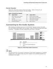
Figure 23. Figure 23 shows the location of the internal headers, observe the precautions in "Before You Begin" on Intel Desktop Board DH55TC. Internal Headers 46 Intel Desktop Board DH55TC Product Guide Connecting to the Internal Headers Before connecting cables to any of the internal headers and connectors on page 27.
Figure 23. Figure 23 shows the location of the internal headers, observe the precautions in "Before You Begin" on Intel Desktop Board DH55TC. Internal Headers 46 Intel Desktop Board DH55TC Product Guide Connecting to the Internal Headers Before connecting cables to any of the internal headers and connectors on page 27.

Product Guide
Page 49
... Front Panel Header Signal Names Pin Description In/Out Pin Description Hard Drive Activity LED Power LED 1 Hard disk LED pull-up to observe the connection polarity. Pins 1 and 3 of the front panel header. Table 10. Reset Switch On/Off Switch 5 Ground 7 Reset switch 6 Power switch In... 8 Ground Power Not Connected 9 Power Out 10 No pin In/Out Out Out In NOTE When connecting individual wires from your chassis has a three-pin power LED cable, connect it to this header duplicate the signals on pins 2 and 4 of this ...
... Front Panel Header Signal Names Pin Description In/Out Pin Description Hard Drive Activity LED Power LED 1 Hard disk LED pull-up to observe the connection polarity. Pins 1 and 3 of the front panel header. Table 10. Reset Switch On/Off Switch 5 Ground 7 Reset switch 6 Power switch In... 8 Ground Power Not Connected 9 Power Out 10 No pin In/Out Out Out In NOTE When connecting individual wires from your chassis has a three-pin power LED cable, connect it to this header duplicate the signals on pins 2 and 4 of this ...

Product Guide
Page 50
... USB 2.0 header and Table 12 shows its pin assignments and signal names. Table 12. Intel Desktop Board DH55TC Product Guide Front Panel USB 2.0 Headers Figure 23, G shows the location of the front panel USB 2.0 header (with...Intel Z-U130 USB Solid-State Drive (or Compatible Device) Support) Signal Names Pin Signal Name 1 +5 VDC 3 D- 5 D+ 7 Ground 9 KEY (no device or a low-speed USB device is attached to the cable. USB 2.0 Header Signal Names Pin Signal Name Pin 1 Power (+5 V) 2 3 D- 4 5 D+ 6 7 Ground 8 9 Key 10 Signal Name Power (+5 V) DD+ Ground No Connection...
... USB 2.0 header and Table 12 shows its pin assignments and signal names. Table 12. Intel Desktop Board DH55TC Product Guide Front Panel USB 2.0 Headers Figure 23, G shows the location of the front panel USB 2.0 header (with...Intel Z-U130 USB Solid-State Drive (or Compatible Device) Support) Signal Names Pin Signal Name 1 +5 VDC 3 D- 5 D+ 7 Ground 9 KEY (no device or a low-speed USB device is attached to the cable. USB 2.0 Header Signal Names Pin Signal Name Pin 1 Power (+5 V) 2 3 D- 4 5 D+ 6 7 Ground 8 9 Key 10 Signal Name Power (+5 V) DD+ Ground No Connection...
Product Guide
Page 51
...) Pin Signal Name 2 RXD# (Receive Data) 4 DTR (Data Terminal Ready) 6 DSR (Data Set Ready) 8 CTS (Clear To Send) 10 Key (no pin) Connecting to power either headphones or amplified speakers only. Back Panel Audio Connectors NOTE The back panel line out connector is designed to the Audio System... After installing the Realtek audio driver from the Intel® Express Installer DVD-ROM, the multi-channel audio feature can be enabled. Table 13 shows the pin assignments and signal names...
...) Pin Signal Name 2 RXD# (Receive Data) 4 DTR (Data Terminal Ready) 6 DSR (Data Set Ready) 8 CTS (Clear To Send) 10 Key (no pin) Connecting to power either headphones or amplified speakers only. Back Panel Audio Connectors NOTE The back panel line out connector is designed to the Audio System... After installing the Realtek audio driver from the Intel® Express Installer DVD-ROM, the multi-channel audio feature can be enabled. Table 13 shows the pin assignments and signal names...

Product Guide
Page 52
Intel Desktop Board DH55TC Product Guide Connecting Chassis Fan and Power Supply Cables Connecting Chassis Fan Cables Connect chassis fan cables to the chassis fan headers on the Desktop Board. Location of the chassis fan headers. Figure 25. Figure 25 shows the location of the Chassis Fan Headers 52
Intel Desktop Board DH55TC Product Guide Connecting Chassis Fan and Power Supply Cables Connecting Chassis Fan Cables Connect chassis fan cables to the chassis fan headers on the Desktop Board. Location of the chassis fan headers. Figure 25. Figure 25 shows the location of the Chassis Fan Headers 52
Product Guide
Page 53
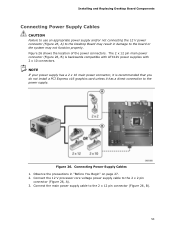
.... Observe the precautions in damage to the power supply. Installing and Replacing Desktop Board Components Connecting Power Supply Cables CAUTION Failure to use an appropriate power supply and/or not connecting the 12 V power connector (Figure 26, A) to the Desktop Board may result in ... 2 x 10 main power connector, it is backwards compatible with ATX12V power supplies with 2 x 10 connectors. Connecting Power Supply Cables 1. Figure 26 shows the location of the power connectors. Connect the 12 V processor core voltage power supply cable to the 2 x 12 pin connector (Figure 26, B). 53...
.... Observe the precautions in damage to the power supply. Installing and Replacing Desktop Board Components Connecting Power Supply Cables CAUTION Failure to use an appropriate power supply and/or not connecting the 12 V power connector (Figure 26, A) to the Desktop Board may result in ... 2 x 10 main power connector, it is backwards compatible with ATX12V power supplies with 2 x 10 connectors. Connecting Power Supply Cables 1. Figure 26 shows the location of the power connectors. Connect the 12 V processor core voltage power supply cable to the 2 x 12 pin connector (Figure 26, B). 53...


