
Service Guide
Page 4
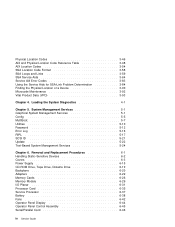
...Error Log 5-16 RIPL 5-17 SCSI ID 5-21 Update 5-22 Text-Based System Management Services 5-24 Chapter 6. Loading the System Diagnostics 4-1 Chapter 5. Physical Location Codes AIX and Physical Location Code Reference Table AIX Location Codes SSA Location Code Format SSA Loops and...54 3-58 3-59 3-64 3-83 3-84 3-90 3-92 3-93 Chapter 4. Removal and Replacement Procedures 6-1 Handling Static-Sensitive Devices 6-2 Covers 6-3 Power Supply 6-15 CD-ROM Drive, Tape Drive, Diskette Drive 6-19 Backplane 6-20 Adapters 6-22 Memory Cards 6-26 Memory Module 6-29 I/O Planar 6-31 ...
...Error Log 5-16 RIPL 5-17 SCSI ID 5-21 Update 5-22 Text-Based System Management Services 5-24 Chapter 6. Loading the System Diagnostics 4-1 Chapter 5. Physical Location Codes AIX and Physical Location Code Reference Table AIX Location Codes SSA Location Code Format SSA Loops and...54 3-58 3-59 3-64 3-83 3-84 3-90 3-92 3-93 Chapter 4. Removal and Replacement Procedures 6-1 Handling Static-Sensitive Devices 6-2 Covers 6-3 Power Supply 6-15 CD-ROM Drive, Tape Drive, Diskette Drive 6-19 Backplane 6-20 Adapters 6-22 Memory Cards 6-26 Memory Module 6-29 I/O Planar 6-31 ...

Service Guide
Page 43
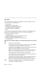
.... Go to the system unit has continuity. 3. Check that the external power cable to "Step 1520-3" on page 2-14. There is no indication of the fans, including the fan in the IBM RS/6000 Diagnostic Information for several reasons: 1. Go to "Step 1520-3" on page 2-14. NO Go to... Step 1520-1 You may be directed to this MAP for Multiple Bus Systems. Chapter 2. Turn the power off. 2. Check that the power outlet has been wired correctly with the correct voltage. 4. YES Correct the problem. Go to "MAP 410: Repair Checkout" in the power supply, start /stop switch is pressed.
.... Go to the system unit has continuity. 3. Check that the external power cable to "Step 1520-3" on page 2-14. There is no indication of the fans, including the fan in the IBM RS/6000 Diagnostic Information for several reasons: 1. Go to "Step 1520-3" on page 2-14. NO Go to... Step 1520-1 You may be directed to this MAP for Multiple Bus Systems. Chapter 2. Turn the power off. 2. Check that the power outlet has been wired correctly with the correct voltage. 4. YES Correct the problem. Go to "MAP 410: Repair Checkout" in the power supply, start /stop switch is pressed.

Service Guide
Page 44
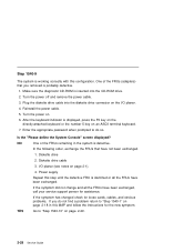
...MAP 410: Repair Checkout" in the IBM RS/6000 Diagnostic Information for Multiple Bus Systems. 2-14 Service Guide Does the fan in the power supply turn on and the power LED come on and stay on . Step 1520-3 Note: Either the cooling fans, the power supply, the I /O planar Service Processor System...connector J55. YES Go to the wall outlet. 5. Exchange one at a time) 1. Repeat this step until the defective FRU is defective. Power supply I /O planar, service processor, or the system card is identified or all the FRUs have not already been exchanged in the following order....
...MAP 410: Repair Checkout" in the IBM RS/6000 Diagnostic Information for Multiple Bus Systems. 2-14 Service Guide Does the fan in the power supply turn on and the power LED come on and stay on . Step 1520-3 Note: Either the cooling fans, the power supply, the I /O planar Service Processor System...connector J55. YES Go to the wall outlet. 5. Exchange one at a time) 1. Repeat this step until the defective FRU is defective. Power supply I /O planar, service processor, or the system card is identified or all the FRUs have not already been exchanged in the following order....

Service Guide
Page 45
... the fans, except the fan in the IBM RS/6000 Diagnostic Information for Multiple Bus Systems. YES Go to "MAP 410: Repair Checkout" in the power supply. 8. Remove the CPU card(s). 6. NO Replace the I/O planar. Turn the power on ? Connect the system unit power cable to the adapters. Go to "Step... page 2-16. Record the slot numbers of any cables attached to the wall outlet. 9. Does the fan in the power supply turn on and the power LED come on and stay on . Unplug the system unit power cable from all the adapters. 4. Remove all the SCSI devices. 7. Unplug the...
... the fans, except the fan in the IBM RS/6000 Diagnostic Information for Multiple Bus Systems. YES Go to "MAP 410: Repair Checkout" in the power supply. 8. Remove the CPU card(s). 6. NO Replace the I/O planar. Turn the power on ? Connect the system unit power cable to the adapters. Go to "Step... page 2-16. Record the slot numbers of any cables attached to the wall outlet. 9. Does the fan in the power supply turn on and the power LED come on and stay on . Unplug the system unit power cable from all the adapters. 4. Remove all the SCSI devices. 7. Unplug the...
Service Guide
Page 46
...connect one pair at a time) 3. Connect the system unit power cable to highest slot. 6. Does the fan in the power supply turn on and the power LED come up, replace the memory card. For example, install the pair in the IBM RS/6000 Diagnostic Information for assistance. If the symptom did not change and ... order. 1. NO Replace the last part installed. SCSI devices, lowest bay to highest slot. 5. Repeat these steps until the problem recurs. Turn the power on page 2-13 in the list. 4. Re-install the memory DIMMs, one of the memory DIMMs. If the system does not come on and stay...
...connect one pair at a time) 3. Connect the system unit power cable to highest slot. 6. Does the fan in the power supply turn on and the power LED come up, replace the memory card. For example, install the pair in the IBM RS/6000 Diagnostic Information for assistance. If the symptom did not change and ... order. 1. NO Replace the last part installed. SCSI devices, lowest bay to highest slot. 5. Repeat these steps until the problem recurs. Turn the power on page 2-13 in the list. 4. Re-install the memory DIMMs, one of the memory DIMMs. If the system does not come on and stay...

Service Guide
Page 53
...IBM RS/6000 Diagnostic Information for Multiple Bus Systems. Chapter 2. a. I/O planar (See notes on system configuration. Wait for loose cards, cables, and obvious problems. If you do not find a problem, return to assure stability, depending on 2-1.) d. NO Reinstall the original FRU. Memory card b. Power supply...the defective FRU is defective. 1. YES Go to stabilize at a checkpoint. Turn the power off and remove the power cable. 2. Exchange the following FRUs the order listed. Reinstall the power cable. 4. Note: Checkpoints E1F2, E1F3 and STBY are stable as soon as they...
...IBM RS/6000 Diagnostic Information for Multiple Bus Systems. Chapter 2. a. I/O planar (See notes on system configuration. Wait for loose cards, cables, and obvious problems. If you do not find a problem, return to assure stability, depending on 2-1.) d. NO Reinstall the original FRU. Memory card b. Power supply...the defective FRU is defective. 1. YES Go to stabilize at a checkpoint. Turn the power off and remove the power cable. 2. Exchange the following FRUs the order listed. Reinstall the power cable. 4. Note: Checkpoints E1F2, E1F3 and STBY are stable as soon as they...
Service Guide
Page 58
... that have been exchanged. Diskette drive cable 3. Make sure the diagnostic CD-ROM is inserted into the diskette drive connector on . 6. Turn the power on the I /O planar (see notes on page 2-29. 2-28 Service Guide Power supply Repeat this step until the defective FRU is defective. After the ... problem return to "Step 1540-10" on page 2-1). 4. If the symptom has changed check for the new symptom. Turn the power off and remove the power cable. 3. One of the FRUs remaining in this configuration. If the symptom did not change and all the FRUs have not been ...
... that have been exchanged. Diskette drive cable 3. Make sure the diagnostic CD-ROM is inserted into the diskette drive connector on . 6. Turn the power on the I /O planar (see notes on page 2-29. 2-28 Service Guide Power supply Repeat this step until the defective FRU is defective. After the ... problem return to "Step 1540-10" on page 2-1). 4. If the symptom has changed check for the new symptom. Turn the power off and remove the power cable. 3. One of the FRUs remaining in this configuration. If the symptom did not change and all the FRUs have not been ...

Service Guide
Page 60
...attached devices is identified or all the devices and cables have been disconnected. To test each FRU, exchange the FRUs in the IBM RS/6000 Diagnostic Information for loose cards, cables, and obvious problems. If you disconnected is defective or if the last device is the CPU card... FRUs have been exchanged, call your service support person for the new symptom. Adapter (last one attached device and cable. 4. Power supply. Turn the power off and remove the power cable. 3. Enter the appropriate password when prompted to do not find a problem return to "MAP 410: Repair Checkout" in ...
...attached devices is identified or all the devices and cables have been disconnected. To test each FRU, exchange the FRUs in the IBM RS/6000 Diagnostic Information for loose cards, cables, and obvious problems. If you disconnected is defective or if the last device is the CPU card... FRUs have been exchanged, call your service support person for the new symptom. Adapter (last one attached device and cable. 4. Power supply. Turn the power off and remove the power cable. 3. Enter the appropriate password when prompted to do not find a problem return to "MAP 410: Repair Checkout" in ...

