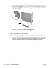
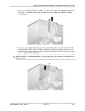
Hardware Reference Guide - dc7700 CMT
Page 27
... cord from the computer. 3. Removing or Installing an Expansion Card The computer has two standard full-height PCI expansion slots that can install a PCI Express x1, x4, x8, or x16 expansion card in length. Figure 2-9 Expansion Slot Locations Item Description 1 PCI expansion slot 2 PCI expansion slot 3 PCI Express x1 expansion slot 4 PCI Express x16 expansion slot NOTE Some models include an optional PCI extender...
Hardware Reference Guide - dc7700 CMT
Page 28
Turn off the computer and remove the power cord before proceeding. 6. Locate the correct vacant expansion socket on the system board and the corresponding expansion slot on the system board as long as the system is plugged into an active AC outlet. If the LED is ...panel, look for the LED on the two green thumb tabs inside the chassis and rotate the expansion card retention latch up. Before installing an expansion card, remove the expansion slot cover or the existing expansion card. 22 Chapter 2 Hardware Upgrades ENWW Remove the computer access panel. Figure 2-10 Opening ...
Hardware Reference Guide - dc7700 CMT
Page 29
... up to remove it back and forth until the connectors pull free from the expansion slot. NOTE Before removing an installed expansion card, disconnect any cables that may be attached to scrape the card against other components. Lift the expansion slot cover from the socket. If you are removing a standard PCI card, hold the card...
Hardware Reference Guide - dc7700 CMT
Page 30
...the removed card in anti-static packaging. 10. Lift the card straight up to remove it with a new card or expansion slot cover for proper cooling of the expansion socket away from the card and carefully rock the card back and forth until the connectors pull free from the socket.... CAUTION After removing an expansion card, you are not installing a new expansion card, install an expansion slot cover to scrape the card against other components...
Hardware Reference Guide - dc7700 CMT
Page 59
... computer operating guidelines 51 connecting drive cables 29 D desktop conversion 36 DIMMs. See memory diskette drive installing 30 removing 27 drives connecting cables 29 installing 29 locations 26 removing 27 E electrostatic discharge, preventing damage 49 expansion card installing 21 removing 21 slot locations 21 expansion slot cover removing 23 replacing 24 H hard drive installing 33...
Hardware Reference Guide - dc7700 CMT
Page 60
R rear panel components 4 removing battery 43 bezel blanks 16 computer access panel 12 drives from drive bay 27 expansion card 21 expansion slot cover 23 front bezel 14 media card reader 27 PCI card 23 PCI Express card 24 Smart Cover Lock 10 S security cable lock 47 padlock 48 Smart Cover Lock 10 serial connector 4 serial number location 7 shipping preparation 52 Smart Cover Lock 10 specifications computer 41 memory 17 U unlocking access panel USB ports front panel 2 rear panel 4 10, 47 V ventilation guidelines 51 W Windows Logo key 6 54 Index ENWW
HP Compaq dc7700 Business Desktop PC Service Reference Guide, 1st Edition
Page 82
... lock and enable the Smart Cover Sensor. 6.10 Expansion Cards 1. Locate the correct vacant expansion socket on the system board and the corresponding expansion slot on the two green thumb tabs inside the chassis and rotate the expansion card retention latch up. 6-12 433612-001 Service Reference Guide, dc7700 Convertible Minitower (CMT) Chassis ✎ The computer...
HP Compaq dc7700 Business Desktop PC Service Reference Guide, 1st Edition
Page 83
... Reference Guide, dc7700 433612-001 6-13 Be sure not to scrape the card against other components. ✎ Before removing an installed expansion card, disconnect any cables that may be attached to release it from the chassis frame. If you are installing an expansion card in a vacant socket, remove the appropriate expansion slot cover on the...
HP Compaq dc7700 Business Desktop PC Service Reference Guide, 1st Edition
Page 84
... of internal components during operation. 6-14 433612-001 Service Reference Guide, dc7700 Lift the expansion card straight up then pull it from a x16 PCI Express socket with a new card or expansion slot cover for proper cooling of the chassis to release it in anti-static... packaging. 9. Removal and Replacement Procedures - If you are not installing a new expansion card, install an expansion slot cover to scrape the card against other components....
HP Compaq dc7700 Business Desktop PC Service Reference Guide, 1st Edition
Page 85
... Cover Lock, use Computer Setup to the system board as needed. 13. Slide the bracket on the end of the expansion card down into the slot on the back of the chassis and press the card down firmly into the socket on the card so that it snaps...- Replace the computer access panel. 14. Service Reference Guide, dc7700 433612-001 6-15 Convertible Minitower (CMT) Chassis 10. Reconfigure the computer, if necessary. Close the expansion slot latch, making sure that the whole connector seats properly in the expansion card socket on the Documentation and Diagnostics CD for instructions about ...
HP Compaq dc7700 Business Desktop PC Service Reference Guide, 1st Edition
Page 86
Removal and Replacement Procedures - Locate the correct vacant expansion socket on the system board and the corresponding expansion slot on the broken plastic latches 1, then complete the removal by pulling the latches off the pivoting bar 2. 6-16 433612-001 Service Reference Guide, dc7700 Use a thin flat blade screwdriver to pry up . 5. Convertible Minitower (CMT) Chassis...
HP Compaq dc7700 Business Desktop PC Service Reference Guide, 1st Edition
Page 130
... the inside of internal components during operation. 7-16 433612-001 Service Reference Guide, dc7700 Remove the computer cover. (Section 7.5). 5. If you are not installing a new expansion card, install an expansion slot cover to unlock the lock. 2. Turn off the computer properly through the operating ...of the computer must contain either an expansion card or slot cover for proper cooling of the chassis. Rotate the slot cover retention latch back in place to secure the expansion cards and expansion slot covers. Ä CAUTION: All expansion card slots on the latch and rotating the ...
HP Compaq dc7700 Business Desktop PC Service Reference Guide, 1st Edition
Page 131
... locked the Smart Cover Lock, use Computer Setup to unlock the lock (Section 7.2). 2. Prepare the computer for disassembly (Section 7.1). 3. Remove all PCI and PCI Express expansion cards from the PCI expansion slots (Section 7.9). 5. Small Form Factor (SFF) Chassis 7.10 PCI Riser Card Assembly and Backwall 1. Service Reference Guide, dc7700 433612-001 7-17
HP Compaq dc7700 Business Desktop PC Service Reference Guide, 1st Edition
Page 135
Install the full-height PCI expansion card in the available slot in a previous step. Service Reference Guide, dc7700 433612-001 7-21 Install the serial connector into the new backwall using the two screws that were removed from the serial connector in the new ... system board. Press down firmly on the system board sits properly over the locking pins. When the system board is properly seated in the PCI expansion slot on the backwall. Install the new PCI riser card cage assembly on the new backwall by aligning the cage with the guide rails on the...
HP Compaq dc7700 Business Desktop PC Service Reference Guide, 1st Edition
Page 177
For a standard PCI expansion card, lay the card cage on its edge and hold it back and forth until the connectors pull free from the cage. Be sure not to step 7. 5. Service Reference Guide, dc7700 433612-001 8-15 Prepare the computer for proper cooling of ... new expansion card, continue with step 8. Ä CAUTION: After removing an expansion card, you are not installing a new expansion card, install an expansion slot cover to remove it with step 5. If you must replace it from the card cage. Remove the computer access panel (Section 8.3). 3. Ultra-Slim Desktop (USDT...
HP Compaq dc7700 Business Desktop PC Service Reference Guide, 1st Edition
Page 262
...and replacement 6-36 chassis, illustrated 5-1 desktop to minitower conversion 6-39 disassembly preparation 6-1 diskette drive bezel removal and replacement 6-8 diskette drive removal and replacement 6-25 drive positions 6-19 expansion card guide removal and replacement 6-18 expansion card removal and replacement 6-13 expansion card retainer latch removal and replacement 6-16 expansion slot cover removal and replacement 6-13, ... and replacement 7-25 SFF hard drive removal and replacement 7-27 SFF optical drive removal and replacement 7-23 Index-2 433612-001 Service Reference Guide, dc7700
HP Compaq dc7700 Business Desktop PC Service Reference Guide, 1st Edition
Page 263
... removal and replacement 8-15 USDTcage removal and replacement 8-14 expansion card retaining latch, USDT removal and replacement 8-17 expansion slot cover CMT removal and replacement 6-13 SFF removal and replacement...HP Backup and Recovery Manager 1-2, 3-2 HP Client Foundation Suite 3-5 HP Client Manager 3-4 HP Client Premium Suite 3-5 HP Insight Diagnostics 2-14 to 2-18 HP OpenView Client Configuration Manager 3-6 HP OpenView PC Management Solution 3-6 HP OpenView See HP OpenView HP ProtectTools Security Manager 3-5 HP System Software Manager 3-4 HPQFlash 3-10 Service Reference Guide, dc7700...
HP Compaq dc7700 Business Desktop PC Service Reference Guide, 1st Edition
Page 265
...CMT bezel blank 6-8 CMT cable lock 6-4 CMT chassis fan 6-36 CMT diskette drive 6-25 CMT diskette drive bezel 6-8 CMT expansion card 6-13 CMT expansion card guide 6-18 CMT expansion slot cover 6-13, 6-16 CMT front bezel 6-6 CMT front I/O device 6-26 CMT hard drive 6-20 CMT hard drive cable... system board 7-39 USDT access panel 8-4 USDT battery 8-26 USDT cable lock 8-3 USDT chassis fan 8-9 USDT expansion card 8-15 USDT expansion card retaining latch 8-17 Service Reference Guide, dc7700 433612-001 Index-5 Index problems, solving audio D-17 CD-ROM and DVD drives D-29 diskette D-7 display D-13...
HP Compaq dx7300 and dc7700 Business PC Technical Reference Guide, 1st Edition
Page 28
... Express x1 slot PCI Express x16 graphics/normal-layout SDVO slot [1] Chassis fan -- -- MT Chassis Layout, Left Side View 2-12 www.hp.com Technical Reference Guide NOTE: [1] Accepts PCI-E graphics or normal-layout ADD2 card. Figure 2-8. System Overview Microtower Chassis Figure 2-8 shows the layout for the Microtower (MT) chassis used for the HP Compaq dx7300...
HP Compaq dx7300 and dc7700 Business PC Technical Reference Guide, 1st Edition
Page 29
...: ■ Externally accessible drive bay assembly may be configured for HP Compaq dc7700 models. System Overview Convertible Minitower Figure 2-9 shows the layout for the Convertible Minitower (CMT) chassis in the minitower configuration used for minitower (vertical) or desktop (horizontal) position. ■ Easy access to expansion slots and all socketed system board components. 1 23 4 5 6 w q - 7 9 8 Item Description 1 Power...