Safety and Regulatory Information Desktops, Thin Clients, and Personal Workstations
Page 26
... 15 minutes 10 minutes 15 minutes 10 minutes 15 minutes 15 minutes Both the computer and monitor can be woken by the EPA. HP computers marked with monitors that is by the EPA to products bearing the Energy Star logo. When used through user interaction with the ...ENERGY STAR Computers Program was created by reducing power consumption when not being used with Wake On LAN (WOL) enabled, the computer can cause video distortion when an Energy Save timeout occurs. 20 Chapter 2 Regulatory Agency Notices ENWW The Power Management feature enables the computer to power down the...
... 15 minutes 10 minutes 15 minutes 10 minutes 15 minutes 15 minutes Both the computer and monitor can be woken by the EPA. HP computers marked with monitors that is by the EPA to products bearing the Energy Star logo. When used through user interaction with the ...ENERGY STAR Computers Program was created by reducing power consumption when not being used with Wake On LAN (WOL) enabled, the computer can cause video distortion when an Energy Save timeout occurs. 20 Chapter 2 Regulatory Agency Notices ENWW The Power Management feature enables the computer to power down the...

Upgrading and Servicing Guide
Page 8
... cover, as required. 4 Upgrading and Servicing Guide T 4 Slide the computer cover back about 1.25 centimeters (1/2 inch), and then lift it aside. 1394 r digitaOl UaTudio wiraenletsesnnLAaN S-VIDEO NOTE: Use the screwdriver slot on the back cover. WARNING: Avoid touching sharp edges inside the computer. Removing the Computer Cover WARNING: Remove power before...
... cover, as required. 4 Upgrading and Servicing Guide T 4 Slide the computer cover back about 1.25 centimeters (1/2 inch), and then lift it aside. 1394 r digitaOl UaTudio wiraenletsesnnLAaN S-VIDEO NOTE: Use the screwdriver slot on the back cover. WARNING: Avoid touching sharp edges inside the computer. Removing the Computer Cover WARNING: Remove power before...

Upgrading and Servicing Guide
Page 10
The following illustration shows component locations: A C digitOaUl aT udiowriaenletesnsnLaAN S-VIDEO E B D 6 Upgrading and Servicing Guide
The following illustration shows component locations: A C digitOaUl aT udiowriaenletesnsnLaAN S-VIDEO E B D 6 Upgrading and Servicing Guide

Upgrading and Servicing Guide
Page 13
Press the two tabs apart at the bottom of the cover, and press the two tabs together at the top of the chassis. Then pull the cage back and out of the cover; Complete the "Opening the Computer" procedures on the Pocket Media Drive cage. digitaOlUauTdio wiraenletsesnLnAaN S-VIDEO 3 If your computer includes a Pocket Media Drive, lift the tab on page 2. 2 Remove the front cover from the computer. Upgrading and Servicing Guide 9 then push the cover out. Removing an Optical Disc Drive 1 Prepare the computer and remove the computer cover.
Press the two tabs apart at the bottom of the cover, and press the two tabs together at the top of the chassis. Then pull the cage back and out of the cover; Complete the "Opening the Computer" procedures on the Pocket Media Drive cage. digitaOlUauTdio wiraenletsesnLnAaN S-VIDEO 3 If your computer includes a Pocket Media Drive, lift the tab on page 2. 2 Remove the front cover from the computer. Upgrading and Servicing Guide 9 then push the cover out. Removing an Optical Disc Drive 1 Prepare the computer and remove the computer cover.
Advanced Setup Guide
Page 3
... the Computer 1 Putting the Computer Together 1 Placing the computer in the proper location 1 Using surge protection 2 Connecting to the computer 2 Connecting a Digital Camera (Photo or Video 8 Connecting Other Devices 10 Storing Documentation and Recovery Discs 10 Adjusting the Monitor 11 Adjusting the screen resolution by using Vista 11 Adjusting the screen...
... the Computer 1 Putting the Computer Together 1 Placing the computer in the proper location 1 Using surge protection 2 Connecting to the computer 2 Connecting a Digital Camera (Photo or Video 8 Connecting Other Devices 10 Storing Documentation and Recovery Discs 10 Adjusting the Monitor 11 Adjusting the screen resolution by using Vista 11 Adjusting the screen...
Advanced Setup Guide
Page 4
... Sound Blaster X-Fi Sound Card 37 Connecting the speakers 37 Connecting the FlexiJack connector 38 Connecting the Television Signal and Video Cables 39 Using TV Cables 39 Audio and Video Cables and Adapters 40 Connecting the TV Signal Source 41 Connecting a dual tuner 42 Connecting the Remote Sensor 43 Connecting...box to VCR to TV, using coaxial cable .......45 Wall to cable TV set-top box or satellite box to VCR and TV, using S-video cable or composite video cable between the box and the VCR or TV ..........46 Using a TV as a Monitor 48 Cables for connecting the computer to a TV...
... Sound Blaster X-Fi Sound Card 37 Connecting the speakers 37 Connecting the FlexiJack connector 38 Connecting the Television Signal and Video Cables 39 Using TV Cables 39 Audio and Video Cables and Adapters 40 Connecting the TV Signal Source 41 Connecting a dual tuner 42 Connecting the Remote Sensor 43 Connecting...box to VCR to TV, using coaxial cable .......45 Wall to cable TV set-top box or satellite box to VCR and TV, using S-video cable or composite video cable between the box and the VCR or TV ..........46 Using a TV as a Monitor 48 Cables for connecting the computer to a TV...
Advanced Setup Guide
Page 5
Connecting to a Monitor or High-Definition TV 51 Choosing the AV connection to use 51 Connecting an HDMI device 53 Connecting a DVI device 54 Connecting to a Standard TV 55 Connecting to component video 55 Connecting to S-video 56 Configuring the TV Tuner 56 Digital versus analog tuner 57 Initial configuration using Windows Media Center setup wizard 57 Changing the tuner settings 58 Index...59 Table of Contents v
Connecting to a Monitor or High-Definition TV 51 Choosing the AV connection to use 51 Connecting an HDMI device 53 Connecting a DVI device 54 Connecting to a Standard TV 55 Connecting to component video 55 Connecting to S-video 56 Configuring the TV Tuner 56 Digital versus analog tuner 57 Initial configuration using Windows Media Center setup wizard 57 Changing the tuner settings 58 Index...59 Table of Contents v

Advanced Setup Guide
Page 9
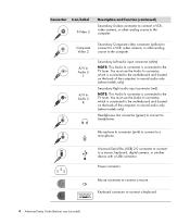
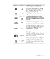
Microphone. FireWire® (IEEE 1394) for some digital cameras or other devices with this 6-pin connector. Side speaker out. Setting Up the Computer 3 Rear speaker out. Audio Line Out (powered speakers). Headphones. Connector Icon/Label Serial Description and function (continued) Serial port for video cameras or other serial devices. NOTE: You must use a 6-pin FireWire (IEEE 1394) transfer cable with very fast transfer rates. Center/Subwoofer. Audio Line In. Digital audio in and digital audio out.
Microphone. FireWire® (IEEE 1394) for some digital cameras or other devices with this 6-pin connector. Side speaker out. Setting Up the Computer 3 Rear speaker out. Audio Line Out (powered speakers). Headphones. Connector Icon/Label Serial Description and function (continued) Serial port for video cameras or other serial devices. NOTE: You must use a 6-pin FireWire (IEEE 1394) transfer cable with very fast transfer rates. Center/Subwoofer. Audio Line In. Digital audio in and digital audio out.
Advanced Setup Guide
Page 10
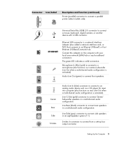
... Serial Bus (USB) 2.0 connector to connect to record audio only (select models only). Headphones Out connector (green) to connect to the computer. Composite Video 2 Secondary Composite video connector (yellow) to connect to a VCR, video camera, or other analog source to a microphone. Microphone In connector (pink) to connect to the computer. Connector Icon/Label...
... Serial Bus (USB) 2.0 connector to connect to record audio only (select models only). Headphones Out connector (green) to connect to the computer. Composite Video 2 Secondary Composite video connector (yellow) to connect to a VCR, video camera, or other analog source to a microphone. Microphone In connector (pink) to connect to the computer. Connector Icon/Label...
Advanced Setup Guide
Page 11
Center Rear Side S-Video Audio Line In (blue) connector to connect to an analog audio device such as a CD player for input into computer (also functions as a center/subwoofer ... In (Mic) (pink) to connect to connect from a set-top box output connector. Universal Serial Bus (USB) 2.0 connector to connect a parallel printer (select models only). S-video In connector to a microphone (also functions as rear Line Out when a multichannel audio configuration is a network interface adapter (also called a network interface card, or NIC...
Center Rear Side S-Video Audio Line In (blue) connector to connect to an analog audio device such as a CD player for input into computer (also functions as a center/subwoofer ... In (Mic) (pink) to connect to connect from a set-top box output connector. Universal Serial Bus (USB) 2.0 connector to connect a parallel printer (select models only). S-video In connector to a microphone (also functions as rear Line Out when a multichannel audio configuration is a network interface adapter (also called a network interface card, or NIC...
Advanced Setup Guide
Page 12
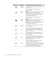
... to the motherboard. Primary right audio input from set -top box connector (red). Connector Icon/Label Composite Video A/V In Audio 1 L A/V In Audio 1 R TV/Cable Ant ATSC CATV NTSC FM Ant Description and function (continued) Composite Video In connector (yellow) to connect to a TV set -top box). Primary left audio input connector on...
... to the motherboard. Primary right audio input from set -top box connector (red). Connector Icon/Label Composite Video A/V In Audio 1 L A/V In Audio 1 R TV/Cable Ant ATSC CATV NTSC FM Ant Description and function (continued) Composite Video In connector (yellow) to connect to a TV set -top box). Primary left audio input connector on...
Advanced Setup Guide
Page 13
... the other end to the computer. HDMI display output connector, which connects to a TV. Setting Up the Computer 7 Analog Video Out: S-video or composite video connector (select models only), which connects to a TV or monitor (select models only). VGA/Monitor (blue) display output connector... audio device with digital input (such as a home audio receiver/amplifier) or digital speakers (select models only). Connector Icon/Label Analog Video VGA/Monitor HDMI DVI Digital Audio Out Description and function (continued) Modem (Line In RJ-11) (select models only). Digital Out ...
... the other end to the computer. HDMI display output connector, which connects to a TV. Setting Up the Computer 7 Analog Video Out: S-video or composite video connector (select models only), which connects to a TV or monitor (select models only). VGA/Monitor (blue) display output connector... audio device with digital input (such as a home audio receiver/amplifier) or digital speakers (select models only). Connector Icon/Label Analog Video VGA/Monitor HDMI DVI Digital Audio Out Description and function (continued) Modem (Line In RJ-11) (select models only). Digital Out ...

Advanced Setup Guide
Page 14
... port on the computer, and wait for the new device. Connecting a Digital Camera (Photo or Video) The following instructions apply only to start. Most digital video cameras use the Video and Audio In connectors on the front or back of the computer. To connect a digital photo ... 3 A Found New Hardware message appears. When installation is complete, a message appears, indicating that came with your digital photo camera or digital video camera. Wait 2 or 3 minutes for Windows Vista to make the necessary settings for the Microsoft® Windows Vista® operating system to ...
... port on the computer, and wait for the new device. Connecting a Digital Camera (Photo or Video) The following instructions apply only to start. Most digital video cameras use the Video and Audio In connectors on the front or back of the computer. To connect a digital photo ... 3 A Found New Hardware message appears. When installation is complete, a message appears, indicating that came with your digital photo camera or digital video camera. Wait 2 or 3 minutes for Windows Vista to make the necessary settings for the Microsoft® Windows Vista® operating system to ...
Advanced Setup Guide
Page 15
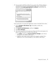
...2 Click System and Maintenance, and then click System. 3 Click Device Manager. 4 Click the plus sign (+) next to install the software. Unplug the video camera transfer cable from the computer, and plug it into a different port. Setting Up the Computer 9 Look in Device Manager for a new addition under...install driver software for hardware changes. If the name is ready. If the computer does not recognize the digital photo camera or the digital video camera: 1 Click the Windows Start Button® Control Panel. If the name of the camera appears, the device is not there, try...
...2 Click System and Maintenance, and then click System. 3 Click Device Manager. 4 Click the plus sign (+) next to install the software. Unplug the video camera transfer cable from the computer, and plug it into a different port. Setting Up the Computer 9 Look in Device Manager for a new addition under...install driver software for hardware changes. If the name is ready. If the computer does not recognize the digital photo camera or the digital video camera: 1 Click the Windows Start Button® Control Panel. If the name of the camera appears, the device is not there, try...
Advanced Setup Guide
Page 16
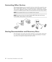
... came with the 6-pin FireWire (IEEE 1394) connector on the computer. It is a good idea to -find, safe location. These peripheral devices include printers, scanners, video cameras, digital photo cameras, memory card readers, and PDAs (personal digital assistants) or handheld computers. NOTE: Some peripheral devices are not included with the documentation...
... came with the 6-pin FireWire (IEEE 1394) connector on the computer. It is a good idea to -find, safe location. These peripheral devices include printers, scanners, video cameras, digital photo cameras, memory card readers, and PDAs (personal digital assistants) or handheld computers. NOTE: Some peripheral devices are not included with the documentation...

Advanced Setup Guide
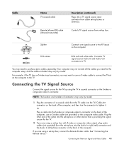
Page 45
... audio cables to the TV. TV signal source video in to the computer. Use the video and audio cables to connect: Video out from the computer to -VGA converter included in the box (select models only). NOTE: The location... the computer. NOTE: Some graphic cards have a DVI connector and a DVI-to the TV. Connecting the Television Signal and Video Cables This section describes how to connect the computer to the television and which cables to use the DVI-to-VGA converter to... connect the VGA cable to the converter and to the monitor. Connecting the Television Signal and Video Cables 39
... audio cables to the TV. TV signal source video in to the computer. Use the video and audio cables to connect: Video out from the computer to -VGA converter included in the box (select models only). NOTE: The location... the computer. NOTE: Some graphic cards have a DVI connector and a DVI-to the TV. Connecting the Television Signal and Video Cables This section describes how to connect the computer to the television and which cables to use the DVI-to-VGA converter to... connect the VGA cable to the converter and to the monitor. Connecting the Television Signal and Video Cables 39
Advanced Setup Guide
Page 46
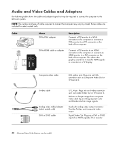
...monitor or a TV display. Delivers a sharper image than composite video cable by model) Plug into a DVI-I or DVI-D cable Y/C, 4-pin. Composite video cable RCA yellow end. Plugs into an RCA connector such as S-video Video Out or TV Source In. Cable Name DVI-to-VGA adapter... card driver to transfer HDMI signals to the television system. S-video cable Analog video cable/adapter (select models only) DVI-I or DVI-D input of the computer. Provides S-video and composite video output. Digital Video Out. Some cables are included for select models only. Used with...
...monitor or a TV display. Delivers a sharper image than composite video cable by model) Plug into a DVI-I or DVI-D cable Y/C, 4-pin. Composite video cable RCA yellow end. Plugs into an RCA connector such as S-video Video Out or TV Source In. Cable Name DVI-to-VGA adapter... card driver to transfer HDMI signals to the television system. S-video cable Analog video cable/adapter (select models only) DVI-I or DVI-D input of the computer. Provides S-video and composite video output. Digital Video Out. Some cables are included for select models only. Used with...
Advanced Setup Guide
Page 47
...Audio In right (red) connector and the Audio In left (white) connector on the computer to the TV. Or Plug a cable into the S-video or composite video In connector on the computer. Cable Name TV coaxial cable Remote Infrared (IR) cable (Infrared transmitter) Description (continued) Plugs into a TV signal ... Connects one signal source to purchase extra cables separately. Your computer may vary by using the TV In coaxial connector or the S-video or composite video In connector. If you need to two RF inputs on the back of the computer. Connects TV signal source Audio In and Audio...
...Audio In right (red) connector and the Audio In left (white) connector on the computer to the TV. Or Plug a cable into the S-video or composite video In connector on the computer. Cable Name TV coaxial cable Remote Infrared (IR) cable (Infrared transmitter) Description (continued) Plugs into a TV signal ... Connects one signal source to purchase extra cables separately. Your computer may vary by using the TV In coaxial connector or the S-video or composite video In connector. If you need to two RF inputs on the back of the computer. Connects TV signal source Audio In and Audio...
Advanced Setup Guide
Page 49
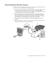
... easily point at it with the remote control. (An ideal spot would be on top of the monitor or desk.) Connecting the Television Signal and Video Cables 43 Connecting the Remote Sensor The remote sensor is a small device that connects to the computer and enables the remote control to work with...
... easily point at it with the remote control. (An ideal spot would be on top of the monitor or desk.) Connecting the Television Signal and Video Cables 43 Connecting the Remote Sensor The remote sensor is a small device that connects to the computer and enables the remote control to work with...

Advanced Setup Guide
Page 51
... cable 1 Disconnect the coaxial cable from the input to the input of computer M Remote control sensor cable N Remote control sensor Connecting the Television Signal and Video Cables 45 Existing setup Setting up the computer with a splitter A Wall B Cable outlet C Coaxial cable D Set-top box/Satellite In E Set-top box/Satellite Out...
... cable 1 Disconnect the coaxial cable from the input to the input of computer M Remote control sensor cable N Remote control sensor Connecting the Television Signal and Video Cables 45 Existing setup Setting up the computer with a splitter A Wall B Cable outlet C Coaxial cable D Set-top box/Satellite In E Set-top box/Satellite Out...

