
Manual
Page 1
... driver, the hard drive may not be able to automatically set up all motherboard drivers, including the X.H.D utility. Using GIGABYTE eXtreme Hard Drive (X.H.D) Instructions:(Note 2) Before launching X.H.D, make sure the new drive is greater than the RAID-ready system...hardware components. 3. B. To automatically set up a RAID 0 array. 2. Setting Up a RAID-Ready System Step 1: Configure the system BIOS Enter the system BIOS Setup program, set up a RAID 0 array: Click Auto to automatically and quickly set eXtreme Hard Drive (X.H.D) under the Integrated Peripherals menu ...
... driver, the hard drive may not be able to automatically set up all motherboard drivers, including the X.H.D utility. Using GIGABYTE eXtreme Hard Drive (X.H.D) Instructions:(Note 2) Before launching X.H.D, make sure the new drive is greater than the RAID-ready system...hardware components. 3. B. To automatically set up a RAID 0 array. 2. Setting Up a RAID-Ready System Step 1: Configure the system BIOS Enter the system BIOS Setup program, set up a RAID 0 array: Click Auto to automatically and quickly set eXtreme Hard Drive (X.H.D) under the Integrated Peripherals menu ...
Manual
Page 3
... The revision number on how to their respective owners. Example: Changes to assist in this manual is protected by GIGABYTE without GIGABYTE's prior written permission. For instructions on your motherboard revision before updating motherboard BIOS, drivers, or when looking for technical information. The trademarks mentioned in this manual are legally registered to use...
... The revision number on how to their respective owners. Example: Changes to assist in this manual is protected by GIGABYTE without GIGABYTE's prior written permission. For instructions on your motherboard revision before updating motherboard BIOS, drivers, or when looking for technical information. The trademarks mentioned in this manual are legally registered to use...
Manual
Page 4
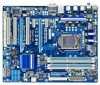
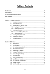
Table of Contents Box Contents...6 Optional Items...6 GA-P55-UD3 Motherboard Layout 7 Block Diagram...8 Chapter 1 Hardware Installation 9 1-1 Installation Precautions 9 1-2 Product Specifications 10 1-3 Installing the CPU and CPU Cooler 13 ... 1-5 Installing an Expansion Card 18 1-6 Back Panel Connectors 19 1-7 Internal Connectors 21 Chapter 2 BIOS Setup 33 2-1 Startup Screen 34 2-2 The Main Menu 35 2-3 MB Intelligent Tweaker(M.I.T 37 2-4 Standard CMOS Features 47 2-5 Advanced BIOS Features 49 2-6 Integrated Peripherals 51 2-7 Power Management Setup 54 2-8 PC Health Status 56 2-9...
Table of Contents Box Contents...6 Optional Items...6 GA-P55-UD3 Motherboard Layout 7 Block Diagram...8 Chapter 1 Hardware Installation 9 1-1 Installation Precautions 9 1-2 Product Specifications 10 1-3 Installing the CPU and CPU Cooler 13 ... 1-5 Installing an Expansion Card 18 1-6 Back Panel Connectors 19 1-7 Internal Connectors 21 Chapter 2 BIOS Setup 33 2-1 Startup Screen 34 2-2 The Main Menu 35 2-3 MB Intelligent Tweaker(M.I.T 37 2-4 Standard CMOS Features 47 2-5 Advanced BIOS Features 49 2-6 Integrated Peripherals 51 2-7 Power Management Setup 54 2-8 PC Health Status 56 2-9...
Manual
Page 5
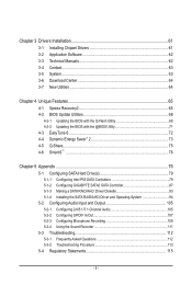
... 65 4-1 Xpress Recovery2 65 4-2 BIOS Update Utilities 68 4-2-1 Updating the BIOS with the Q-Flash Utility 68 4-2-2 Updating the BIOS with the @BIOS Utility 71 4-3 EasyTune 6...72 4-4 Dynamic Energy Saver™ 2 73 4-5 Q-Share...75 4-6 Smart 6™ ...76 Chapter 5 Appendix...79 5-1 Configuring SATA Hard Drive(s 79 5-1-1 Configuring Intel P55 SATA Controllers 79 5-1-2 Configuring GIGABYTE SATA2 SATA Controller 87...
... 65 4-1 Xpress Recovery2 65 4-2 BIOS Update Utilities 68 4-2-1 Updating the BIOS with the Q-Flash Utility 68 4-2-2 Updating the BIOS with the @BIOS Utility 71 4-3 EasyTune 6...72 4-4 Dynamic Energy Saver™ 2 73 4-5 Q-Share...75 4-6 Smart 6™ ...76 Chapter 5 Appendix...79 5-1 Configuring SATA Hard Drive(s 79 5-1-1 Configuring Intel P55 SATA Controllers 79 5-1-2 Configuring GIGABYTE SATA2 SATA Controller 87...

Manual
Page 8
... CLK (100 MHz) x1 2 PCI Express x1 2 SATA 3Gb/s ATA-133/100/66/33 IDE Channel PCI Bus GIGABYTE SATA2 DMI Interface 1 PCI Express x4 x4 PCI Express Bus Intel® P55 Dual BIOS 6 SATA 3Gb/s 14 USB Ports LPC Bus IT8720 Floppy COM Port LPT CODEC PS/2 KB/Mouse Surround Speaker Out...
... CLK (100 MHz) x1 2 PCI Express x1 2 SATA 3Gb/s ATA-133/100/66/33 IDE Channel PCI Bus GIGABYTE SATA2 DMI Interface 1 PCI Express x4 x4 PCI Express Bus Intel® P55 Dual BIOS 6 SATA 3Gb/s 14 USB Ports LPC Bus IT8720 Floppy COM Port LPT CODEC PS/2 KB/Mouse Surround Speaker Out...

Manual
Page 11
... 1 x RJ-45 port 6 x audio jacks (Center/Subwoofer Speaker Out/Rear Speaker Out/ Side Speaker Out/Line In/Line Out/Microphone) iTE IT8720 chip Hardware Monitor w w w w w w BIOS w w w w System voltage detection CPU/System temperature detection CPU/System/Power fan speed detection CPU overheating warning CPU/System/Power fan fail warning CPU/System fan...
... 1 x RJ-45 port 6 x audio jacks (Center/Subwoofer Speaker Out/Rear Speaker Out/ Side Speaker Out/Line In/Line Out/Microphone) iTE IT8720 chip Hardware Monitor w w w w w w BIOS w w w w System voltage detection CPU/System temperature detection CPU/System/Power fan speed detection CPU overheating warning CPU/System/Power fan fail warning CPU/System fan...
Manual
Page 12
Hardware Installation - 12 - Unique Features w w w w w w w w w w Bundled Software w Support for @BIOS Support for Q-Flash Support for Xpress BIOS Rescue Support for Download Center Support for Xpress Install Support for Xpress Recovery2 Support for EasyTune (Note 5) Support for Dynamic Energy Saver™ 2 Support for ...
Hardware Installation - 12 - Unique Features w w w w w w w w w w Bundled Software w Support for @BIOS Support for Q-Flash Support for Xpress BIOS Rescue Support for Download Center Support for Xpress Install Support for Xpress Recovery2 Support for EasyTune (Note 5) Support for Dynamic Energy Saver™ 2 Support for ...

Manual
Page 16
... before installing the memory to install it in the DDR3_1 or DDR3_3 sockets. Hardware Installation - 16 - After the memory is installed, the BIOS will double the original memory bandwidth. When enabling Dual Channel mode with two memory modules, be enabled if only one DDR3 memory module is... DS/SS DS/SS DS/SS DS/SS (SS=Single-Sided, DS=Double-Sided, "- -"=No Memory) DDR3_2 DDR3_1 DDR3_4 DDR3_3 Due to GIGABYTE's website for optimum performance. 1-4 Installing the Memory Read the following guidelines before you are divided into two channels and each channel has two memory...
... before installing the memory to install it in the DDR3_1 or DDR3_3 sockets. Hardware Installation - 16 - After the memory is installed, the BIOS will double the original memory bandwidth. When enabling Dual Channel mode with two memory modules, be enabled if only one DDR3 memory module is... DS/SS DS/SS DS/SS DS/SS (SS=Single-Sided, DS=Double-Sided, "- -"=No Memory) DDR3_2 DDR3_1 DDR3_4 DDR3_3 Due to GIGABYTE's website for optimum performance. 1-4 Installing the Memory Read the following guidelines before you are divided into two channels and each channel has two memory...
Manual
Page 18
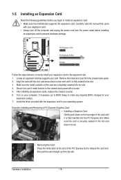
... chassis back panel with your operating system. PCI Express x1 Slot PCI Express x16 Slot PCI Slot Follow the steps below to make any required BIOS changes for your expansion card in your expansion card. • Always turn off the computer and unplug the power cord from the chassis back panel.... 2. Locate an expansion slot that came with a screw. 5. If necessary, go to BIOS Setup to correctly install your expansion card(s). 7. Install the driver provided with the slot, and press down on your card.
... chassis back panel with your operating system. PCI Express x1 Slot PCI Express x16 Slot PCI Slot Follow the steps below to make any required BIOS changes for your expansion card in your expansion card. • Always turn off the computer and unplug the power cord from the chassis back panel.... 2. Locate an expansion slot that came with a screw. 5. If necessary, go to BIOS Setup to correctly install your expansion card(s). 7. Install the driver provided with the slot, and press down on your card.
Manual
Page 25
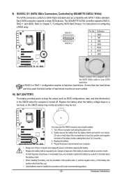
... battery with local environmental regulations. - 25 - Plug in the power cord and restart your computer. • Always turn off your SATA hard drive. The GIGABYTE SATA2 controller supports RAID 0, RAID 1, and JBOD. If more than two hard drives are not able to keep the values (such as... BIOS configurations, date, and time information) in accordance with an equivalent one minute. (Or use a metal object like a screwdriver to Chapter 5, "Configuring SATA Hard Drive(s)," for...
... battery with local environmental regulations. - 25 - Plug in the power cord and restart your computer. • Always turn off your SATA hard drive. The GIGABYTE SATA2 controller supports RAID 0, RAID 1, and JBOD. If more than two hard drives are not able to keep the values (such as... BIOS configurations, date, and time information) in accordance with an equivalent one minute. (Or use a metal object like a screwdriver to Chapter 5, "Configuring SATA Hard Drive(s)," for...
Manual
Page 26
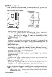
RESRES+ CICI+ PWR+ PWR- The LED is off when the system is detected, the BIOS may issue beeps in different patterns to the speaker on the chassis front panel. Press the reset switch to restart the computer if the computer .../sensor on the chassis that can detect if the chassis cover has been removed. When connecting your system using the power switch (refer to Chapter 2, "BIOS Setup," "Power Management Setup," for information about beep codes. • HD (Hard Drive Activity LED, Blue) Connects to the pin assignments below. Message/Power/ Power...
RESRES+ CICI+ PWR+ PWR- The LED is off when the system is detected, the BIOS may issue beeps in different patterns to the speaker on the chassis front panel. Press the reset switch to restart the computer if the computer .../sensor on the chassis that can detect if the chassis cover has been removed. When connecting your system using the power switch (refer to Chapter 2, "BIOS Setup," "Power Management Setup," for information about beep codes. • HD (Hard Drive Activity LED, Blue) Connects to the pin assignments below. Message/Power/ Power...
Manual
Page 30
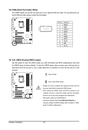
...1 NDCD- 9 1 2 NSIN 10 2 3 NSOUT 4 NDTR- 5 GND 6 NDSR- 7 NRTS- 8 NCTS- 9 NRI- 10 No Pin 19) CLR_CMOS (Clearing CMOS Jumper) Use this jumper to Chapter 2, "BIOS Setup," for a few seconds. Failure to do so may cause damage to the motherboard. • After system restart, go to... and before turning on the two pins to temporarily short the two pins or use a metal object like a screwdriver to touch the two pins for BIOS configurations). Hardware Installation - 30 - Open: Normal Short: Clear CMOS Values • Always turn off your computer, be sure to factory defaults. To ...
...1 NDCD- 9 1 2 NSIN 10 2 3 NSOUT 4 NDTR- 5 GND 6 NDSR- 7 NRTS- 8 NCTS- 9 NRI- 10 No Pin 19) CLR_CMOS (Clearing CMOS Jumper) Use this jumper to Chapter 2, "BIOS Setup," for a few seconds. Failure to do so may cause damage to the motherboard. • After system restart, go to... and before turning on the two pins to temporarily short the two pins or use a metal object like a screwdriver to touch the two pins for BIOS configurations). Hardware Installation - 30 - Open: Normal Short: Clear CMOS Values • Always turn off your computer, be sure to factory defaults. To ...
Manual
Page 33
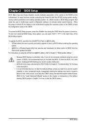
To upgrade the BIOS, use either the GIGABYTE Q-Flash or @BIOS utility. • Q-Flash allows the user to quickly and easily upgrade or back up BIOS without entering the operating system. • @BIOS is turned on the motherboard supplies the necessary power to the CMOS to the "Load Optimized Defaults" section... on . When the power is potentially risky, if you need to) to boot. To see more advanced BIOS Setup menu options, you not flash the BIOS. BIOS includes a BIOS Setup program that searches and downloads the latest version of the battery/ clearing CMOS jumper in the CMOS on ...
To upgrade the BIOS, use either the GIGABYTE Q-Flash or @BIOS utility. • Q-Flash allows the user to quickly and easily upgrade or back up BIOS without entering the operating system. • @BIOS is turned on the motherboard supplies the necessary power to the CMOS to the "Load Optimized Defaults" section... on . When the power is potentially risky, if you need to) to boot. To see more advanced BIOS Setup menu options, you not flash the BIOS. BIOS includes a BIOS Setup program that searches and downloads the latest version of the battery/ clearing CMOS jumper in the CMOS on ...
Manual
Page 34
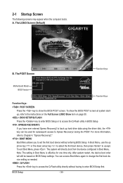
... still be used for one time only. Note: The setting in BIOS Setup. : XPRESS RECOVERY2 If you to show the BIOS POST screen at system startup, refer to accept. Motherboard Model BIOS Version P55-UD3 D13c . . . . : BIOS Setup : XpressRecovery2 : Boot Menu : Qflash 07/13/2009-P55-7A89RG0KC-00 Function Keys Function Keys Function Keys: : POST SCREEN Press...
... still be used for one time only. Note: The setting in BIOS Setup. : XPRESS RECOVERY2 If you to show the BIOS POST screen at system startup, refer to accept. Motherboard Model BIOS Version P55-UD3 D13c . . . . : BIOS Setup : XpressRecovery2 : Boot Menu : Qflash 07/13/2009-P55-7A89RG0KC-00 Function Keys Function Keys Function Keys: : POST SCREEN Press...
Manual
Page 35
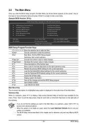
... Main Menu (as usual, select the Load Optimized Defaults item to set your system to its defaults. • The BIOS Setup menus described in this chapter are for the menu. BIOS Setup 2-2 The Main Menu Once you want in the Main Menu or a submenu, press + to access more advanced ...Password Save & Exit Setup Exit Without Saving Select Item F10: Save & Exit Setup Change CPU's Clock & Voltage F11: Save CMOS to BIOS F12: Load CMOS from BIOS BIOS Setup Program Function Keys Move the selection bar to select an item Execute command or enter the submenu Main Menu: Exit the...
... Main Menu (as usual, select the Load Optimized Defaults item to set your system to its defaults. • The BIOS Setup menus described in this chapter are for the menu. BIOS Setup 2-2 The Main Menu Once you want in the Main Menu or a submenu, press + to access more advanced ...Password Save & Exit Setup Exit Without Saving Select Item F10: Save & Exit Setup Change CPU's Clock & Voltage F11: Save CMOS to BIOS F12: Load CMOS from BIOS BIOS Setup Program Function Keys Move the selection bar to select an item Execute command or enter the submenu Main Menu: Exit the...
Manual
Page 36
...integrated audio, and integrated LAN, etc. Power Management Setup Use this menu to configure all changes and the previous settings remain in BIOS Setup. Set User Password Change, set , or disable password. First select the profile you wish to load, then press to complete... Intelligent Tweaker(M.I.T.) Use this menu to configure the clock, frequency and voltages of your system becomes unstable and you have loaded the BIOS default settings, you to see information about autodetected system/CPU temperature, system voltage and fan speed, etc. Load Fail-Safe...
...integrated audio, and integrated LAN, etc. Power Management Setup Use this menu to configure all changes and the previous settings remain in BIOS Setup. Set User Password Change, set , or disable password. First select the profile you wish to load, then press to complete... Intelligent Tweaker(M.I.T.) Use this menu to configure the clock, frequency and voltages of your system becomes unstable and you have loaded the BIOS default settings, you to see information about autodetected system/CPU temperature, system voltage and fan speed, etc. Load Fail-Safe...
Manual
Page 37
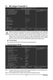
If this feature. BIOS Setup Incorrectly doing overclock/overvoltage may result in damage to CPU, chipset, or memory and reduce the useful life of these components. Current Status This ... Frequency Settings } Advanced Memory Settings } Advanced Voltage Settings } Miscellaneous Settings [Press Enter] [Press Enter] [Press Enter] [Press Enter] [Press Enter] Item Help Menu Level BIOS Version BCLK CPU Frequency Memory Frequency Total Memory Size D13c 133.27 MHz 2931.89 MHz 1332.80 MHz 2048MB CPU Temperature PCH Temperature 45oC...
If this feature. BIOS Setup Incorrectly doing overclock/overvoltage may result in damage to CPU, chipset, or memory and reduce the useful life of these components. Current Status This ... Frequency Settings } Advanced Memory Settings } Advanced Voltage Settings } Miscellaneous Settings [Press Enter] [Press Enter] [Press Enter] [Press Enter] [Press Enter] Item Help Menu Level BIOS Version BCLK CPU Frequency Memory Frequency Total Memory Size D13c 133.27 MHz 2931.89 MHz 1332.80 MHz 2048MB CPU Temperature PCH Temperature 45oC...
Manual
Page 38
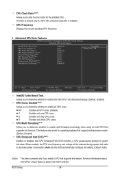
... ratio for operating systems that supports this feature. CPU Multi-Threading (Note) Allows you install a CPU that supports this function. Auto lets the BIOS automatically configure this setting. (Default: Auto) (Note) This item is installed. This feature only works for the installed CPU.... BIOS Setup - 38 - CPU Cores Enabled (Note) CPU Multi-Threading (Note) CPU Enhanced Halt (C1E) (Note) C3/C6/C7 State Support (Note) CPU Thermal Monitor ...
... ratio for operating systems that supports this feature. CPU Multi-Threading (Note) Allows you install a CPU that supports this function. Auto lets the BIOS automatically configure this setting. (Default: Auto) (Note) This item is installed. This feature only works for the installed CPU.... BIOS Setup - 38 - CPU Cores Enabled (Note) CPU Multi-Threading (Note) CPU Enhanced Halt (C1E) (Note) C3/C6/C7 State Support (Note) CPU Thermal Monitor ...
Manual
Page 39
...enabled, the CPU core frequency and voltage will be reduced during system halt state to decrease power consumption. Auto lets the BIOS automatically configure this setting. (Default) Enabled When the CPU or chipset detects that an overheating is present only if you ...Enables or disables Intel CPU Thermal Monitor function, a CPU overheating protection function. Auto lets the BIOS automatically configure this setting. (Default: Auto) Bi-Directional PROCHOT (Note) Auto Lets the BIOS automatically configure this setting. (Default: Auto) CPU EIST Function (Note) Enables or disables ...
...enabled, the CPU core frequency and voltage will be reduced during system halt state to decrease power consumption. Auto lets the BIOS automatically configure this setting. (Default) Enabled When the CPU or chipset detects that an overheating is present only if you ...Enables or disables Intel CPU Thermal Monitor function, a CPU overheating protection function. Auto lets the BIOS automatically configure this setting. (Default: Auto) Bi-Directional PROCHOT (Note) Auto Lets the BIOS automatically configure this setting. (Default: Auto) CPU EIST Function (Note) Enables or disables ...

Manual
Page 40
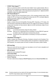
... performance. Disabled Disables this feature. Auto sets the PCIe clock frequency to 1200 MHz. Extreme Memory Profile (X.M.P.) (Note) Allows the BIOS to read the SPD data on system components, when system instability occurs after overclocking, please wait for 20 seconds to allow the BCLK... overclocking, lower the overclocking ratio. (Note) This item appears only if you to the BCLK Frequency(Mhz) and System Memory Multiplier settings. BIOS Setup - 40 - Enabled will allow for automated system reboot, or clear the CMOS values to reset the board to default values. (Default...
... performance. Disabled Disables this feature. Auto sets the PCIe clock frequency to 1200 MHz. Extreme Memory Profile (X.M.P.) (Note) Allows the BIOS to read the SPD data on system components, when system instability occurs after overclocking, please wait for 20 seconds to allow the BCLK... overclocking, lower the overclocking ratio. (Note) This item appears only if you to the BCLK Frequency(Mhz) and System Memory Multiplier settings. BIOS Setup - 40 - Enabled will allow for automated system reboot, or clear the CMOS values to reset the board to default values. (Default...


