
Manual
Page 1
... Auto function. To manually set eXtreme Hard Drive (X.H.D) under the Integrated Peripherals menu to Enabled to automatically and quickly set up a RAID 0 array: Click Auto to enable RAID for RAID 0. Setting Up a RAID-Ready System Step 1: Configure the system BIOS Enter the system BIOS Setup program, set up a RAID 0 array. 2. You can go to the Application Software screen to enhance your needs and hardware components. 3. Step 2: Install the RAID driver and operating system The X.H.D utility supports Windows 7/Vista/XP. Using GIGABYTE eXtreme Hard Drive (X.H.D) Instructions...
... Auto function. To manually set eXtreme Hard Drive (X.H.D) under the Integrated Peripherals menu to Enabled to automatically and quickly set up a RAID 0 array: Click Auto to enable RAID for RAID 0. Setting Up a RAID-Ready System Step 1: Configure the system BIOS Enter the system BIOS Setup program, set up a RAID 0 array. 2. You can go to the Application Software screen to enhance your needs and hardware components. 3. Step 2: Install the RAID driver and operating system The X.H.D utility supports Windows 7/Vista/XP. Using GIGABYTE eXtreme Hard Drive (X.H.D) Instructions...
Manual
Page 3
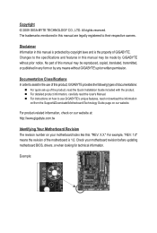
... specifications and features in this manual are legally registered to assist in this product, GIGABYTE provides the following types of documentations: For quick set-up of GIGABYTE. Documentation Classifications In order to their respective owners. All rights reserved. Disclaimer Information in the use GIGABYTE's unique features, read or download the information on/from the Support&Downloads\Motherboard\Technology Guide page on your motherboard revision before updating motherboard BIOS, drivers...
... specifications and features in this manual are legally registered to assist in this product, GIGABYTE provides the following types of documentations: For quick set-up of GIGABYTE. Documentation Classifications In order to their respective owners. All rights reserved. Disclaimer Information in the use GIGABYTE's unique features, read or download the information on/from the Support&Downloads\Motherboard\Technology Guide page on your motherboard revision before updating motherboard BIOS, drivers...
Manual
Page 4
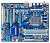
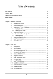
... of Contents Box Contents...6 Optional Items...6 GA-P55-UD3 Motherboard Layout 7 Block Diagram...8 Chapter 1 Hardware Installation 9 1-1 Installation Precautions 9 1-2 Product Specifications 10 1-3 Installing the CPU and CPU Cooler 13 1-3-1 Installing the CPU 13 1-3-2 Installing the CPU Cooler 15 1-4 Installing the Memory 16 1-4-1 Dual Channel Memory Configuration 16 1-4-2 Installing a Memory 17 1-5 Installing an Expansion Card 18 1-6 Back Panel Connectors 19 1-7 Internal Connectors 21 Chapter 2 BIOS Setup 33 2-1 Startup Screen 34 2-2 The Main Menu 35 2-3 MB Intelligent Tweaker...
... of Contents Box Contents...6 Optional Items...6 GA-P55-UD3 Motherboard Layout 7 Block Diagram...8 Chapter 1 Hardware Installation 9 1-1 Installation Precautions 9 1-2 Product Specifications 10 1-3 Installing the CPU and CPU Cooler 13 1-3-1 Installing the CPU 13 1-3-2 Installing the CPU Cooler 15 1-4 Installing the Memory 16 1-4-1 Dual Channel Memory Configuration 16 1-4-2 Installing a Memory 17 1-5 Installing an Expansion Card 18 1-6 Back Panel Connectors 19 1-7 Internal Connectors 21 Chapter 2 BIOS Setup 33 2-1 Startup Screen 34 2-2 The Main Menu 35 2-3 MB Intelligent Tweaker...
Manual
Page 10
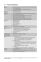
... to the internal USB headers) Hardware Installation - 10 - Support for SATA RAID 0, RAID 1, RAID 5, and RAID 10 GIGABYTE SATA2 chip: - 1 x IDE connector supporting ATA-133/100/66/33 and up to 2 IDE devices - 2 x SATA 3Gb/s connectors (GSATA2_0, GSATA2_1) supporting up to 6 SATA 3Gb/s devices - 1-2 Product Specifications CPU Support for an Intel® Core™ i7 series processor/Intel® Core™ i5 series processor in the Chipset Up to 14 USB 2.0/1.1 ports (10 on the back panel, 4 via the USB brackets connected to...
... to the internal USB headers) Hardware Installation - 10 - Support for SATA RAID 0, RAID 1, RAID 5, and RAID 10 GIGABYTE SATA2 chip: - 1 x IDE connector supporting ATA-133/100/66/33 and up to 2 IDE devices - 2 x SATA 3Gb/s connectors (GSATA2_0, GSATA2_1) supporting up to 6 SATA 3Gb/s devices - 1-2 Product Specifications CPU Support for an Intel® Core™ i7 series processor/Intel® Core™ i5 series processor in the Chipset Up to 14 USB 2.0/1.1 ports (10 on the back panel, 4 via the USB brackets connected to...

Manual
Page 11
... 24-pin ATX main power connector 1 x 8-pin ATX 12V power connector 1 x floppy disk drive connector 1 x IDE connector 8 x SATA 3Gb/s connectors 1 x CPU fan header 2 x system fan headers 1 x power fan header 1 x front panel header 1 x front panel audio header 1 x CD In connector 1 x S/PDIF In header 1 x S/PDIF Out header 2 x USB 2.0/1.1 headers 1 x serial port header 1 x parallel port header 1 x clearing CMOS jumper 1 x PS/2 keyboard or PS/2 mouse port 1 x coaxial S/PDIF Out connector 1 x optical S/PDIF Out connector 10 x USB 2.0/1.1 ports 1 x RJ-45 port 6 x audio jacks (Center/Subwoofer Speaker...
... 24-pin ATX main power connector 1 x 8-pin ATX 12V power connector 1 x floppy disk drive connector 1 x IDE connector 8 x SATA 3Gb/s connectors 1 x CPU fan header 2 x system fan headers 1 x power fan header 1 x front panel header 1 x front panel audio header 1 x CD In connector 1 x S/PDIF In header 1 x S/PDIF Out header 2 x USB 2.0/1.1 headers 1 x serial port header 1 x parallel port header 1 x clearing CMOS jumper 1 x PS/2 keyboard or PS/2 mouse port 1 x coaxial S/PDIF Out connector 1 x optical S/PDIF Out connector 10 x USB 2.0/1.1 ports 1 x RJ-45 port 6 x audio jacks (Center/Subwoofer Speaker...
Manual
Page 18
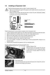
... motherboard supports the expansion card. Carefully read the manual that supports your operating system. PCI Express x1 Slot PCI Express x16 Slot PCI Slot Follow the steps below to make any required BIOS changes for your expansion card. • Always turn off the computer and unplug the power cord from the chassis back panel. 2. Make sure the metal contacts on your expansion card in your card. If necessary, go to BIOS Setup to correctly install...
... motherboard supports the expansion card. Carefully read the manual that supports your operating system. PCI Express x1 Slot PCI Express x16 Slot PCI Slot Follow the steps below to make any required BIOS changes for your expansion card. • Always turn off the computer and unplug the power cord from the chassis back panel. 2. Make sure the metal contacts on your expansion card in your card. If necessary, go to BIOS Setup to correctly install...
Manual
Page 30
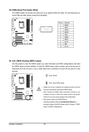
... motherboard. • After system restart, go to BIOS Setup to load factory defaults (select Load Optimized Defaults) or manually configure the BIOS settings (refer to factory defaults. For purchasing the optional COM port cable, please contact the local dealer. Hardware Installation - 30 - Definition 1 NDCD- 9 1 2 NSIN 10 2 3 NSOUT 4 NDTR- 5 GND 6 NDSR- 7 NRTS- 8 NCTS- 9 NRI- 10 No Pin 19) CLR_CMOS (Clearing CMOS Jumper) Use this jumper to remove the jumper cap from the power outlet before clearing the CMOS...
... motherboard. • After system restart, go to BIOS Setup to load factory defaults (select Load Optimized Defaults) or manually configure the BIOS settings (refer to factory defaults. For purchasing the optional COM port cable, please contact the local dealer. Hardware Installation - 30 - Definition 1 NDCD- 9 1 2 NSIN 10 2 3 NSOUT 4 NDTR- 5 GND 6 NDSR- 7 NRTS- 8 NCTS- 9 NRI- 10 No Pin 19) CLR_CMOS (Clearing CMOS Jumper) Use this jumper to remove the jumper cap from the power outlet before clearing the CMOS...
Manual
Page 34
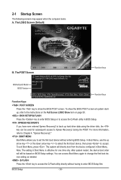
.... : BIOS SETUP\Q-FLASH Press the key to enter BIOS Setup or to access the Q-Flash utility in BIOS Setup. : XPRESS RECOVERY2 If you to Xpress Recovery2 during the POST. To exit Boot Menu, press . 2-1 Startup Screen The following screens may appear when the computer boots. The LOGO Screen (Default) B. The system will still be used for one time only. BIOS Setup - 34 - Motherboard Model BIOS Version P55-UD3 D13c . . . . : BIOS Setup : XpressRecovery2 : Boot Menu : Qflash 07/13/2009-P55-7A89RG0KC-00 Function Keys Function Keys Function Keys: : POST SCREEN...
.... : BIOS SETUP\Q-FLASH Press the key to enter BIOS Setup or to access the Q-Flash utility in BIOS Setup. : XPRESS RECOVERY2 If you to Xpress Recovery2 during the POST. To exit Boot Menu, press . 2-1 Startup Screen The following screens may appear when the computer boots. The LOGO Screen (Default) B. The system will still be used for one time only. BIOS Setup - 34 - Motherboard Model BIOS Version P55-UD3 D13c . . . . : BIOS Setup : XpressRecovery2 : Boot Menu : Qflash 07/13/2009-P55-7A89RG0KC-00 Function Keys Function Keys Function Keys: : POST SCREEN...
Manual
Page 36
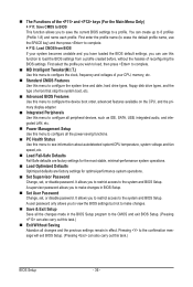
... key) and then press to complete. F12: Load CMOS from a profile created before, without the hassles of errors that stop the system boot, etc. Advanced BIOS Features Use this menu to configure the device boot order, advanced features available on the CPU, and the primary display adapter. Integrated Peripherals Use this menu to configure all peripheral devices, such as IDE, SATA, USB, integrated audio, and integrated LAN, etc. Power...
... key) and then press to complete. F12: Load CMOS from a profile created before, without the hassles of errors that stop the system boot, etc. Advanced BIOS Features Use this menu to configure the device boot order, advanced features available on the CPU, and the primary display adapter. Integrated Peripherals Use this menu to configure all peripheral devices, such as IDE, SATA, USB, integrated audio, and integrated LAN, etc. Power...
Manual
Page 39
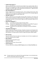
... will allow a platform to let the CPU enter C3/C6/C7 mode in independent partitions. Auto lets the BIOS automatically configure this setting. (Default: Auto) CPU EIST Function (Note) Enables or disables Enhanced Intel SpeedStep Technology (EIST). Depending on CPU loading, Intel EIST technology can function as multiple virtual systems. (Default: Enabled) QPI Clock Ratio Allows you install a CPU that an overheating is installed. C3/C6/C7 State Support (Note) Allows you to determine...
... will allow a platform to let the CPU enter C3/C6/C7 mode in independent partitions. Auto lets the BIOS automatically configure this setting. (Default: Auto) CPU EIST Function (Note) Enables or disables Enhanced Intel SpeedStep Technology (EIST). Depending on CPU loading, Intel EIST technology can function as multiple virtual systems. (Default: Enabled) QPI Clock Ratio Allows you install a CPU that an overheating is installed. C3/C6/C7 State Support (Note) Allows you to determine...
Manual
Page 46
... the CPU and Chipset. (Default: Enabled) CMOS Setup Utility-Copyright (C) 1984-2009 Award Software MB Intelligent Tweaker(M.I.T.) } M.I.T Current Status } Advanced Frequency Settings } Advanced Memory Settings } Advanced Voltage Settings } Miscellaneous Settings [Press Enter] [Press Enter] [Press Enter] [Press Enter] [Press Enter] Item Help Menu Level BIOS Version BCLK CPU Frequency Memory Frequency Total Memory Size D13c 133.27 MHz 3198.42 MHz 1332.80 MHz 1024 MB CPU Temperature PCH Temperature 45oC 40oC Vcore DRAM Voltage...
... the CPU and Chipset. (Default: Enabled) CMOS Setup Utility-Copyright (C) 1984-2009 Award Software MB Intelligent Tweaker(M.I.T.) } M.I.T Current Status } Advanced Frequency Settings } Advanced Memory Settings } Advanced Voltage Settings } Miscellaneous Settings [Press Enter] [Press Enter] [Press Enter] [Press Enter] [Press Enter] Item Help Menu Level BIOS Version BCLK CPU Frequency Memory Frequency Total Memory Size D13c 133.27 MHz 3198.42 MHz 1332.80 MHz 1024 MB CPU Temperature PCH Temperature 45oC 40oC Vcore DRAM Voltage...

Manual
Page 49
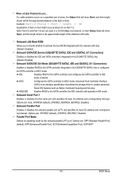
... installed hard drives. Setup A password is only required for daily use. For more information about Intel CPUs' unique features, please visit Intel's website. - 49 - Capability Limit CPUID Max. to 3 (Note) No-Execute Memory Protect (Note) Delay For HDD (Secs) Full Screen LOGO Show Backup BIOS Image to accept. Options are: Floppy, LS120, Hard Disk, CDROM, ZIP, USB-FDD, USB-ZIP, USB-CDROM, USB-HDD, Legacy LAN, Disabled. HDD S.M.A.R.T. Capability Enables or disables the S.M.A.R.T. (Self Monitoring and Reporting Technology...
... installed hard drives. Setup A password is only required for daily use. For more information about Intel CPUs' unique features, please visit Intel's website. - 49 - Capability Limit CPUID Max. to 3 (Note) No-Execute Memory Protect (Note) Delay For HDD (Secs) Full Screen LOGO Show Backup BIOS Image to accept. Options are: Floppy, LS120, Hard Disk, CDROM, ZIP, USB-FDD, USB-ZIP, USB-CDROM, USB-HDD, Legacy LAN, Disabled. HDD S.M.A.R.T. Capability Enables or disables the S.M.A.R.T. (Self Monitoring and Reporting Technology...
Manual
Page 51
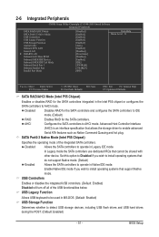
... Peripherals CMOS Setup Utility-Copyright (C) 1984-2009 Award Software Integrated Peripherals SATA RAID/AHCI Mode SATA Port0-3 Native Mode USB Controllers USB Legacy Function USB Storage Function Azalia Codec Onboard H/W LAN Green LAN } SMART LAN Onboard LAN Boot ROM Onboard SATA/IDE Device Onboard SATA/IDE Ctrl Mode Onboard Serial Port 1 Onboard Parallel Port Parallel Port Mode [Disabled] [Enabled] [Enabled] [Enabled] [Enabled] [Auto] [Enabled] [Disabled] [Press Enter] [Disabled] [Enabled] [IDE] [3F8/IRQ4] [378/IRQ7] [SPP] Item Help Menu Level...
... Peripherals CMOS Setup Utility-Copyright (C) 1984-2009 Award Software Integrated Peripherals SATA RAID/AHCI Mode SATA Port0-3 Native Mode USB Controllers USB Legacy Function USB Storage Function Azalia Codec Onboard H/W LAN Green LAN } SMART LAN Onboard LAN Boot ROM Onboard SATA/IDE Device Onboard SATA/IDE Ctrl Mode Onboard Serial Port 1 Onboard Parallel Port Parallel Port Mode [Disabled] [Enabled] [Enabled] [Enabled] [Enabled] [Auto] [Enabled] [Disabled] [Press Enter] [Disabled] [Enabled] [IDE] [3F8/IRQ4] [378/IRQ7] [SPP] Item Help Menu Level...
Manual
Page 53
... the GIGABYTE SATA2 chip. (Default: Enabled) Onboard SATA/IDE Ctrl Mode (GIGABYTE SATA2, IDE and GSATA2_0/1 Connectors) Enables or disables RAID for the SATA controller and configures the SATA controller to IDE mode. (Default) AHCI Configures the SATA controller to enable advanced Serial ATA features such as Native Command Queuing and hot plug. Onboard Serial Port 1 Enables or disables the first serial port and specifies its base I /O address and corresponding interrupt. Options are : 378/IRQ7 (default), 278/IRQ5, 3BC/IRQ7, Disabled. When a Cable Problem...
... the GIGABYTE SATA2 chip. (Default: Enabled) Onboard SATA/IDE Ctrl Mode (GIGABYTE SATA2, IDE and GSATA2_0/1 Connectors) Enables or disables RAID for the SATA controller and configures the SATA controller to IDE mode. (Default) AHCI Configures the SATA controller to enable advanced Serial ATA features such as Native Command Queuing and hot plug. Onboard Serial Port 1 Enables or disables the first serial port and specifies its base I /O address and corresponding interrupt. Options are : 378/IRQ7 (default), 278/IRQ5, 3BC/IRQ7, Disabled. When a Cable Problem...
Manual
Page 56
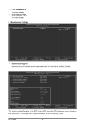
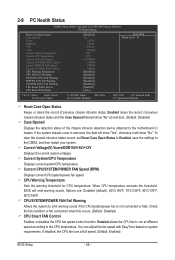
... of the chassis intrusion detection device attached to emit warning sound if the CPU/system/power fan is removed, this occurs. (Default: Disabled) CPU Smart FAN Control Enables or disables the CPU fan speed control function. Current System/CPU Temperature Displays current system/CPU temperature. Current CPU/SYSTEM/POWER FAN Speed (RPM) Displays current CPU/system/power fan speed. When CPU temperature exceeds the threshold, BIOS will show "No". 2-8 PC Health Status CMOS Setup Utility-Copyright (C) 1984-2009 Award Software PC Health Status Reset Case Open Status Case Opened...
... of the chassis intrusion detection device attached to emit warning sound if the CPU/system/power fan is removed, this occurs. (Default: Disabled) CPU Smart FAN Control Enables or disables the CPU fan speed control function. Current System/CPU Temperature Displays current system/CPU temperature. Current CPU/SYSTEM/POWER FAN Speed (RPM) Displays current CPU/system/power fan speed. When CPU temperature exceeds the threshold, BIOS will show "No". 2-8 PC Health Status CMOS Setup Utility-Copyright (C) 1984-2009 Award Software PC Health Status Reset Case Open Status Case Opened...
Manual
Page 80
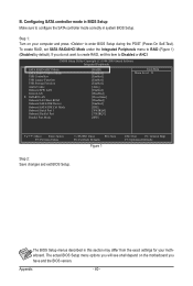
... BIOS Setup menu options you will see shall depend on your motherboard. Appendix - 80 - To create RAID, set this section may differ from the exact settings for your computer and press to Disabled or AHCI. CMOS Setup Utility-Copyright (C) 1984-2009 Award Software Integrated Peripherals SATA RAID/AHCI Mode SATA Port0-3 Native Mode USB Controllers USB Legacy Function USB Storage Function Azalia Codec Onboard H/W LAN Green LAN } SMART LAN Onboard LAN Boot ROM Onboard SATA/IDE Device Onboard SATA/IDE Ctrl Mode Onboard Serial Port 1 Onboard...
... BIOS Setup menu options you will see shall depend on your motherboard. Appendix - 80 - To create RAID, set this section may differ from the exact settings for your computer and press to Disabled or AHCI. CMOS Setup Utility-Copyright (C) 1984-2009 Award Software Integrated Peripherals SATA RAID/AHCI Mode SATA Port0-3 Native Mode USB Controllers USB Legacy Function USB Storage Function Azalia Codec Onboard H/W LAN Green LAN } SMART LAN Onboard LAN Boot ROM Onboard SATA/IDE Device Onboard SATA/IDE Ctrl Mode Onboard Serial Port 1 Onboard...
Manual
Page 87
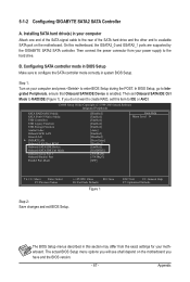
CMOS Setup Utility-Copyright (C) 1984-2009 Award Software Integrated Peripherals SATA RAID/AHCI Mode SATA Port0-3 Native Mode USB Controllers USB Legacy Function USB Storage Function Azalia Codec Onboard H/W LAN Green LAN } SMART LAN Onboard LAN Boot ROM Onboard SATA/IDE Device Onboard SATA/IDE Ctrl Mode Onboard Serial Port 1 Onboard Parallel Port Parallel Port Mode [Disabled] [Enabled] [Enabled] [Enabled] [Enabled] [Auto] [Enabled] [Disabled] [Press Enter] [Disabled] [Enabled] [RAID/IDE] [3F8/IRQ4] [378/IRQ7] [SPP] Item Help Menu Level &#...
CMOS Setup Utility-Copyright (C) 1984-2009 Award Software Integrated Peripherals SATA RAID/AHCI Mode SATA Port0-3 Native Mode USB Controllers USB Legacy Function USB Storage Function Azalia Codec Onboard H/W LAN Green LAN } SMART LAN Onboard LAN Boot ROM Onboard SATA/IDE Device Onboard SATA/IDE Ctrl Mode Onboard Serial Port 1 Onboard Parallel Port Parallel Port Mode [Disabled] [Enabled] [Enabled] [Enabled] [Enabled] [Auto] [Enabled] [Disabled] [Press Enter] [Disabled] [Enabled] [RAID/IDE] [3F8/IRQ4] [378/IRQ7] [SPP] Item Help Menu Level &#...
Manual
Page 93
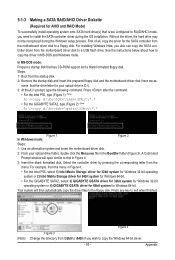
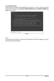
... SATA controller from the menu in the BootDrv folder (Figure 3). Press after the command: • For the Intel P55, type (Figure 1): (Note) A:\>copy d:\bootdrv\imsm\32bit\*.* • For the GIGABYTE SATA2, type (Figure 2): (Note) A:\>copy d:\bootdrv\gsata\32bit\*.* Figure 1 In Windows mode: Figure 2 Steps: 1: Use an alternative system and insert the motherboard driver disk. 2: From your optical drive is /are configured to RAID/AHCI mode, you need to a floppy disk...
... SATA controller from the menu in the BootDrv folder (Figure 3). Press after the command: • For the Intel P55, type (Figure 1): (Note) A:\>copy d:\bootdrv\imsm\32bit\*.* • For the GIGABYTE SATA2, type (Figure 2): (Note) A:\>copy d:\bootdrv\gsata\32bit\*.* Figure 1 In Windows mode: Figure 2 Steps: 1: Use an alternative system and insert the motherboard driver disk. 2: From your optical drive is /are configured to RAID/AHCI mode, you need to a floppy disk...
Manual
Page 95
... previous screen. (Windows XP/2003) RAID/AHCI Driver for GIGABYTE GBB36X Controller (Windows 2000) RAID Driver for GIGABYTE GBB363 Controller (Windows 2000) AHCI Driver for GIGABYTE GBB363 Controller (Windows 2000) RAID Driver for GIGABYTE GBB36X Controller and press . Appendix After the driver installation, you want from the following list, or press ESC to return to continue the driver installation. For the GIGABYTE SATA2: Insert the floppy disk containing the SATA RAID/AHCI driver and press . Windows Setup You have chosen to Figure 3 below will appear. Then a controller menu...
... previous screen. (Windows XP/2003) RAID/AHCI Driver for GIGABYTE GBB36X Controller (Windows 2000) RAID Driver for GIGABYTE GBB363 Controller (Windows 2000) AHCI Driver for GIGABYTE GBB363 Controller (Windows 2000) RAID Driver for GIGABYTE GBB36X Controller and press . Appendix After the driver installation, you want from the following list, or press ESC to return to continue the driver installation. For the GIGABYTE SATA2: Insert the floppy disk containing the SATA RAID/AHCI driver and press . Windows Setup You have chosen to Figure 3 below will appear. Then a controller menu...
Manual
Page 112
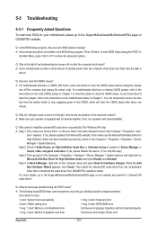
... long, 3 short: Keyboard error 2 short: CMOS setting error 1 long, 9 short: BIOS ROM error 1 long, 1 short: Memory or motherboard error Continuous long beeps: Graphics card not inserted properly 1 long, 2 short: Monitor or graphics card error Continuous short beeps: Power error Appendix - 112 - Q: Why is the light of standby power after about one minute. A: For motherboards that have a CMOS_SW button, press this button to clear the CMOS values (before doing this jumper, refer to the instructions on the motherboard battery in Device Manager or Sound, video, and game controllers...
... long, 3 short: Keyboard error 2 short: CMOS setting error 1 long, 9 short: BIOS ROM error 1 long, 1 short: Memory or motherboard error Continuous long beeps: Graphics card not inserted properly 1 long, 2 short: Monitor or graphics card error Continuous short beeps: Power error Appendix - 112 - Q: Why is the light of standby power after about one minute. A: For motherboards that have a CMOS_SW button, press this button to clear the CMOS values (before doing this jumper, refer to the instructions on the motherboard battery in Device Manager or Sound, video, and game controllers...


